


150
- Data Brochure
One Stage Setpoint Control 150
12/08
D 150
HEAT
F
Setpoint
Differential
Delay/Cycle
The tekmar One Stage Setpoint Control 150 is a microprocessor-based control that
can be programmed
to maintain a fixed setpoint temperature by cycling a heating or cooling device using either bang-bang
or Pulse Width Modulated (PWM) output control.
This reliable and versatile control has a very wide setpoint range, an adjustable differential and time
delay that makes it useable in many different applications. The control has a digital LCD window that
normally shows the actual sensor temperature and can be used to view the setpoint as well as the other
programmed settings.
A Universal sensor 071 is supplied with the control. The wire to the sensor may be extended up to 500 ft.
(150m) by standard 18 AWG low voltage wire. The display will indicate a sensor fault whenever the
sensor is either open or short circuited.
Technical specifications
Settings
Temperature display — -85 to 302°F (-65 to 150°C)
Setpoint — -40 to 239°F (-40 to 115°C)
Differential (Bang/Bang) — 1 to 40°F (1 to 22°C)
Differential range (PWM) — 3 to 40°F (2 to 22°C)
Time delay (Bang/Bang) — 0 to 19 min. 50 sec.
(10 second increments)
Cycle length (PWM) — 30 sec. to 19 min. 50 sec.
(10 second increments)
Operating mode — Heating/Cooling
Temperature scale — Fahrenheit/Celsius
Programmed settings — Ten year memory
backup
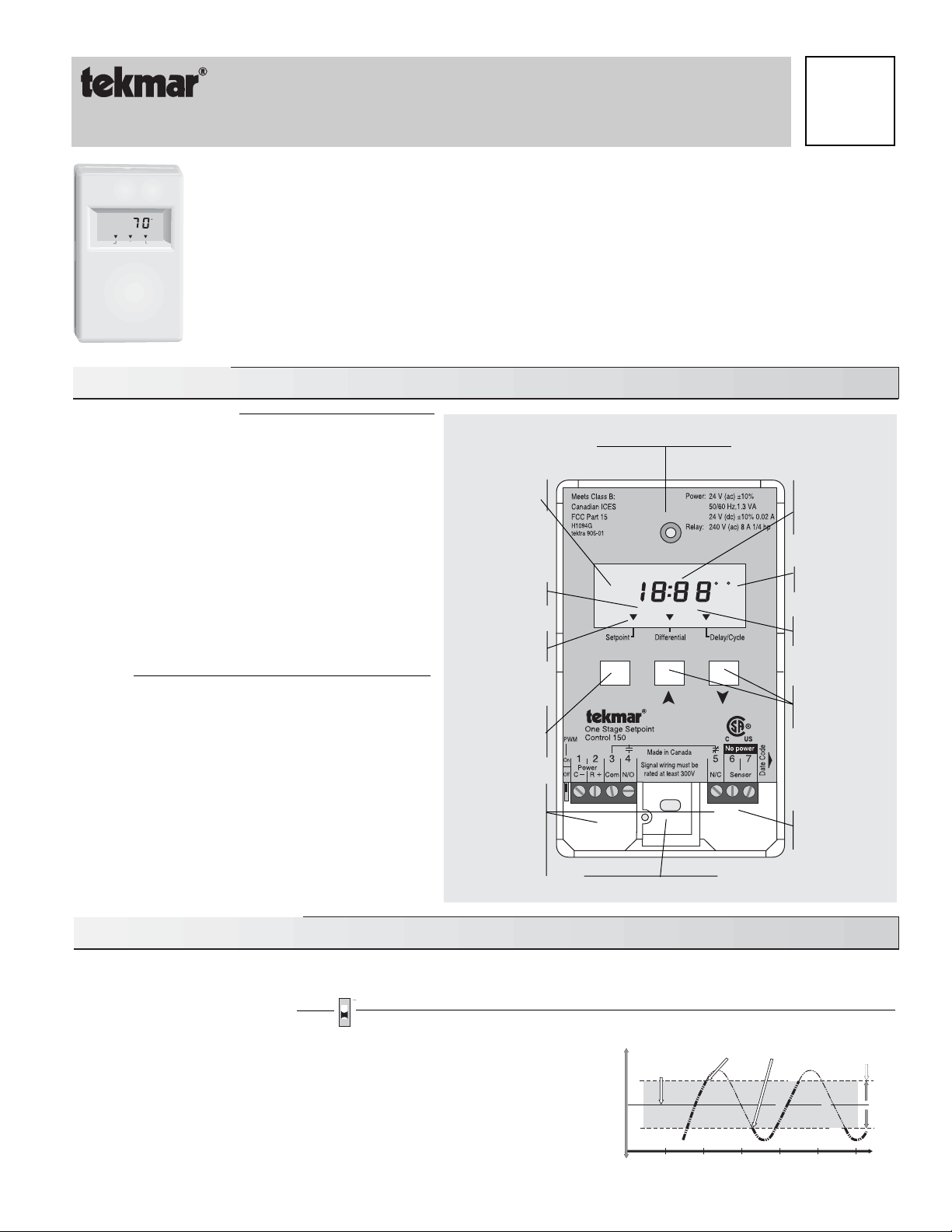
• When the One Stage Setpoint Control 150 is powered-up
the digital display will show all of the display elements. The control
will then monitor the sensor temperature and display it in the digital display. (See diagram)
Technical Data
PRGM
HEAT COOL
FC
Hole for mounting screw
Wiring Chamber;
Terminals for
24Vac power
supply and
control circuit
for heating/
cooling device
Item
selection
and display
button
Wiring Chamber;
Terminals for
Sensor
°C or °F
indicators
Cooling mode
indicator
Programming
and display
buttons
Heating mode
indicator
Programming
mode indicator
Temperature,
Differential and
Delay/Cycle
Display
Bang - Bang Operating Mode
Bang-Bang control outputs turn equipment on when there is a demand for heating
or cooling, and then shut it completely off when the demand is satisfied.
• If the control is programmed for “Heat”
in this mode, it turns on its relay and
the “HEAT” display element when the sensor temperature is (a) — 1/2 the
differential setting below the setpoint,
and
(b) — the delay has timed out.
When the sensor
temperature rises 1/2 the differential setting above the
setpoint, the relay switches off , the “HEAT” display element turns off and the
delay starts to time out.
During the time out period, the Delay/Cycle pointer
will flash if heating is needed.
Sequence of Operation
Desired temperature
this example
160°F(71°C)
Temperature
WarmerCooler
Time
Differential
this example
1 0 °F ( 5 °C )
165°F(74°C)
155°F(68°C)
T
e
m
p
e
r
a
t
u
r
e
f
a
l
l
CONTROL RELAY (HEATING)
OFF ON
T
e
m
p
e
r
a
t
u
r
e
r
i
s
e
Item
Identifiers
Hole for mounting screw
PWM
Dip Switch Down
Dimensions — 2-7/8" x 4-3/4" x 7/8”
)mm 22 x 021 x 47(
Gross Weight — 1 lb (450g)
Ambient — -20 to 120°F (-30 to 50°C)
gnisnednoc-non HR % 09<
Power supply — 24 V (ac) ±10%, 50/60 Hz, 1.3 VA
A 20.0 %01± )cd( V 42
Relay — 240 V (ac) 8 A 1/4 hp
Sensor — 10 kΩ @77°F (25° ± 0.2°C),
rotsimreht CTN ,3 evruc
.tf 005 ot pu htiw etarucca
eriw eguag 81 fo )m051(
Control accuracy — ±0.5°F (±0.3°C) at 70°F (21°C)
Item
Caution
Improper installation and operation of this control could result in damage to equipment and possibly even personal injury.
It is your responsibility to ensure that this control is safely installed according to all applicable codes and standards.
Step One Getting ready
Check the contents of this package. If any of the contents listed are missing or damaged, please refer to the Limited Warranty
and Product Return Procedure on the back of this brochure and contact your wholesaler or tekmar sales agent for assistance.
Type 150 includes:
• One Control 150 • One Universal Sensor 071
• One Data Brochure D 150 • One Data Brochure D 001 • One Data Brochure D 070
Other information available:
• Essay E 001
Note: Carefully read the Sequence of Operation section in this brochure to ensure that you have chosen the proper control and
understand its functions within the operational requirements of your system.
Step Two
Mounting
The control is mounted in accordance with the instructions in the Data Brochure D 001.
Step Three
Rough-in wiring
All electrical wiring terminates in the two wiring chambers at the bottom front of the control. If the control is to be mounted on
an electrical box, the wiring can be roughed-in at the electrical box prior to installation of the control (see Brochure D 001).
Standard 18 AWG solid wire is recommended for all low voltage wiring to this control.
Caution: Power should not be applied to any of the wires during this rough-in wiring stage.
• Install the Universal Sensor 071, according to the instructions in Data Brochure D 070 and run the wiring back to the control
but don’t connect.
• Install a 24 V (ac) Class 2 transformer with a minimum 5 VA rating close to the control, and run the wiring from the transformer
to the control.
A Class 2 transformer must be used. Do not connect any of the transformer terminals to ground.
• Install the wiring from the heating/cooling device control circuit to the control.
Step Four
Testing and connecting the wiring
Caution
These tests are to be performed using standard testing practices and procedures and should only be carried out by
a properly trained and experienced technician. A good quality electrical test meter, capable of reading from at least
0 — 200 Volts AC, and at least 0 — 2,000,000 Ohms, is essential to properly test this control. At no time should voltages
in excess of 28 V (ac) be measured at any of the wires connected to this control.
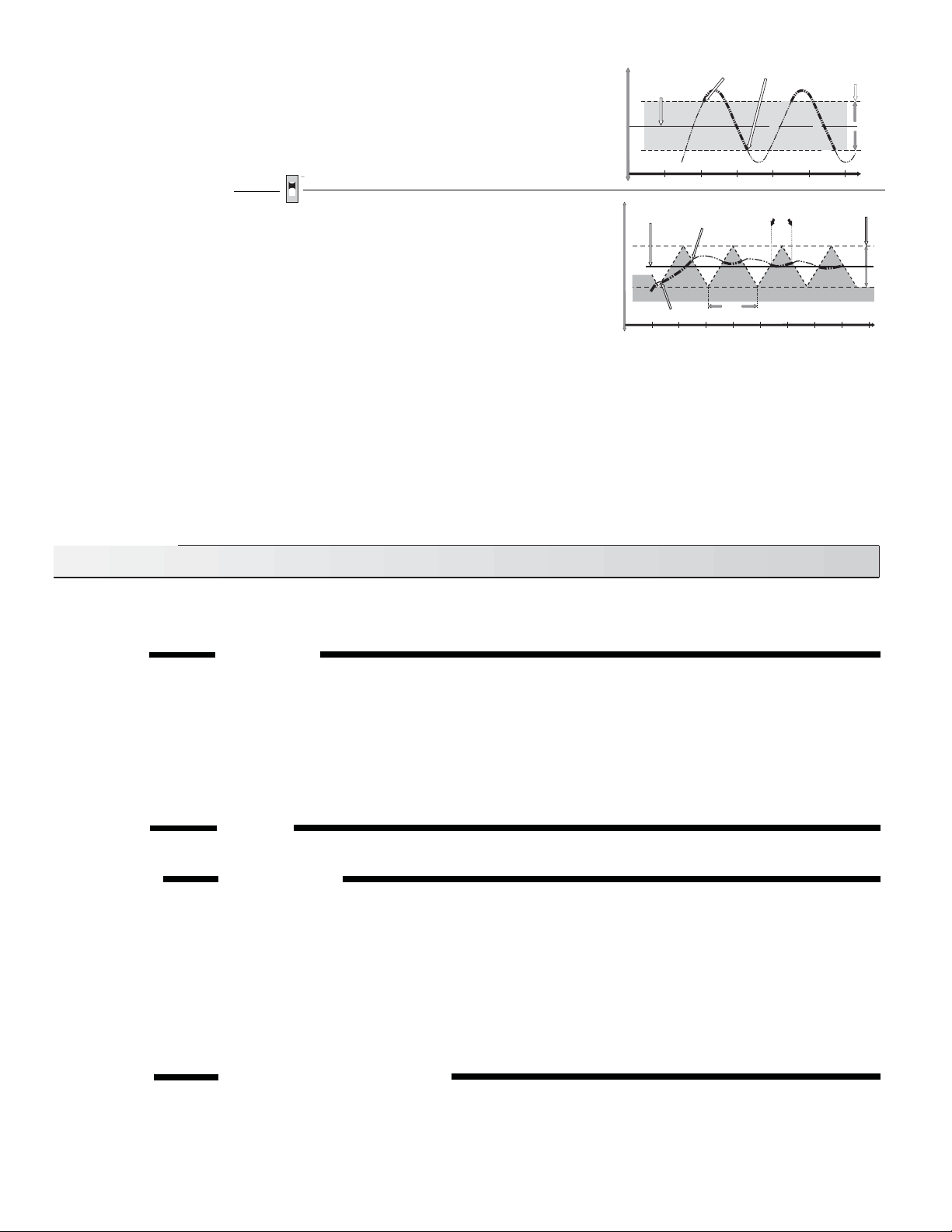
• If the control is programmed for “Heat”
in this mode, the relay is off as long as the sensor temperature is 1/2 the differential setting
above the setpoint. The relay is continually on when the sensor temperature is 1/2 the differential below the setpoint. If the sensor
temperature is between these two points, PWM action occurs. As more heat is required, the relay “on” time is increased and
the “off” time is decreased within each cycle. As less heat is required, the relay “on” time is decreased and the “off” time is increased
within each cycle.
• If the control is programmed for “Cool”
in this mode, the relay is continually on when the sensor temperature is 1/2 the differential
setting above the setpoint. The relay is off when the sensor temperature is 1/2 the differential below the setpoint. If the sensor
temperature is between these two points, PWM action occurs. As more cooling is required, the relay “on” time is increased and
the “off” time is decreased within each cycle. As less cooling is required, the relay “on” time is decreased and the “off” time is increased
within each cycle .
Caution— If PWM is selected, the minimum time delay is disabled.
PWM Operating Mode
The Pulse Width Modulation (PWM) control output is an on/off action, but differs from
the simple bang-bang by changing the length of the “on” time based on how much
the actual temperature differs from the desired temperature. With the advance to
PWM output, overshoot and undershoot is reduced by adding a quantity based
function. The heating device is not simply operated “when” heat is needed but the
operation is varied depending on “how much” heat is needed.
Desired temperature
this example
40°F(4°C)
Temperature
WarmerCooler
Time
Differential
this example
10°F(5°C)
45°F(7°C)
35°F(2°C)
T
e
m
p
e
r
a
t
u
r
e
f
a
l
l
CONTROL RELAY (COOLING)
ON OFF
T
e
m
p
e
r
a
t
u
r
e
r
i
s
e
RELAY ON
RELAY OFF
Pulse
Width
Desired temperature;
(Setting, this example
68° F) 19°C
PWM Zone;
(Differential Setting,
this example
4° F (2°C)
Cycle
length
Temperature
WarmerCooler
Time
T
e
m
p
e
r
a
t
u
r
e
Heating
• If the control is programmed for “Cool”
in this mode, it turns on its relay and
shows the “COOL” display element when the sensor temperature is (a) — 1/
2 the differential setting above the setpoint,
and
(b) — the delay has timed out.
When the sensor
temperature drops 1/2 the differential setting below the
setpoint, the relay switches off, the “COOL” display element turns off and the
delay starts to time out.
During the time out period, the Delay/Cycle pointer will
flash if cooling is needed.
PWM
Dip Switch Up
2
Installation
 Loading...