


- Data Brochure |
D 512 |
||
Programmable Thermostat 512 |
|
09/09 |
|
|
|
|
|
|
|
|
|
Table of Contents |
|
|
|
Display / Keypad Operation |
............ pg 1 |
View Menu................................ |
pg 6 |
Display Symbols ............................. |
pg 2 |
Adjust Menu ........................ |
pg 7-10 |
General ........................................ |
pg 2-3 |
Error Messages ...................... |
pg 11 |
Sequence of Operation................ |
pg 4-6 |
Installation................................. |
pg 12-13 |
Type 512 (Two Stage Heating)... pg 4 |
Wiring the 512 ........................... |
pg 14-17 |
|
Type 512 (Heat / Cool) ............ |
pg 5-6 |
Warranty ....................................... |
pg 20 |
Menus ........................................ |
pg 6-10 |
|
|
Display / Keypad Operation
The thermostat’s display has four distinct fields. These fields are the Menu field, the Item field, the Number field and the Status field. The four buttons on the face of the thermostat are used to navigate through the menus and items to view and / or adjust the desired settings.
Displays the |
|
|
Displays an abbreviated |
|
current |
|
|
name of the selected item |
|
menu |
|
|
|
|
|
|
|
|
|
|
|
|
|
|
|
|
|
|
|
|
|
|
|
|
|
|
|
|
|
Displays the current value
of the selected item
Displays the current status of the thermostat's inputs, outputs and operation
Selects Menus, Items
and adjusts settings
1 of 20 |
© 2009 |
D 512 - 09/09 |

Display Symbols
Warning
Displays when an error exists.
Access Level
Displays when in the user access level.
Early Start
Displays when the thermostat is in early start.
General
CYCLES PER HOUR (HEAT CYCLE and COOL CYCLE)
The thermostat operation is based on cycles per hour. |
|
|
Cycles Per Hour |
||||||||
The number of cycles per hour is adjustable through |
|
|
|
|
|
|
|
|
|
|
|
|
|
|
|
|
|
|
|
|
|
|
|
the HEAT CYCLE and COOL CYCLE settings in the |
on |
off |
|
on |
|
|
off |
on |
off |
||
|
|
|
|
|
|
|
|
|
|
|
|
Adjust menu. During each cycle that heating or cooling |
|
|
|
Cycle Length |
|
|
|
||||
|
|
|
|
|
|
||||||
is required, the thermostat turns on the Heat or Cool |
|
|
|
|
|
|
|||||
|
|
|
|
|
Time |
|
|
|
|
||
relay(s) for a calculated amount of time. This amount of |
|
|
|
|
|
|
|
|
|
||
|
|
|
|
|
|
|
|
|
|
|
|
time is the “on time”. The on time is calculated based on |
|
|
|
|
|
|
|
|
|
|
|
the requirements of the zone. If the zone requires more heating or cooling, the appropriate on time is increased. If the zone requires less heat or cooling, the appropriate on time is reduced.
In order to prevent short cycling of the heating relay(s), the thermostat ensures that the relay(s) remains on or off for a minimum amount of time. In order to prevent short cycling of the Cool relay, the minimum cooling on time and minimum cooling off time settings are adjusted in the Adjust menu of the 512.
An Auto Cycle setting is available for both the heating cycle and the cooling cycle. This setting allows the thermostat to determine the best number of cycles per hour that balances both temperature swings and equipment cycles.
EARLY START ( |
) |
|
|
70°F (21°C) |
|
|
|
|
Early Start OFF |
|
|
|
|
|||||||
|
|
|
|
|
|
|||||||||||||||
Heating - The early start function for heating |
|
|
|
|
|
|
|
|
|
|
|
|
|
|
|
|||||
|
|
|
|
|
|
|
|
|
|
|
|
|
|
|
|
|
||||
ensures that the zone is up to the proper |
62°F (17°C) |
|
|
|
|
|
|
|
|
|
|
|
|
|
|
|
||||
temperature at the beginning of each period. |
|
|
|
|
|
|
|
|
|
|
|
|
|
|
|
|
|
|||
The thermostat learns the recovery rate over |
|
|
|
|
|
Early Start ON |
|
|
|
|
||||||||||
multiple setback events in order to determine |
70°F (21°C) |
|
|
|
|
|
|
|
|
|
|
|
|
|
|
|
||||
|
|
|
|
|
||||||||||||||||
the proper lead time for the zone. If both an |
62°F (17°C) |
|
|
|
|
|
|
|
|
|
|
|
|
|
|
|
||||
air sensor and a slab sensor are used, the |
|
|
|
|
|
|
|
|
|
|
|
|
|
|
|
|||||
|
|
|
|
|
UnOccupied |
|
|
|
|
|
|
|
Occupied |
|
|
|
||||
|
|
|
|
|
|
|
|
|
|
|
|
|
|
|
|
|
|
|
||
|
|
|
|
|
|
|
|
|
|
|
|
|
||||||||
|
|
|
|
|
|
|
|
|
|
|
|
|
|
|
|
|
|
|
|
|
lead time is the greater of the air sensor’s or the slab sensor’s requirements.
Cooling - The early start function, when used with cooling, allows the cooling system to turn on 30 minutes prior to the beginning of a period that requires cooling.
NOTE: The Early Start feature occurs when the schedule changes from a low temperature to a higher temperature.
© 2009 |
D 512 - 09/09 |
2 of 20 |
AUXILIARY SENSORS
The thermostat has a single built-in sensor to measure air temperature at the thermostat. In addition to the built-in sensor, the thermostat has terminals to connect up to two separate sensors. These sensors can be either indoor sensors, slab sensors, a remote sensor, or an outdoor sensor.
Indoor Sensor
An indoor sensor is used to measure the air temperature in the zone that the thermostat is controlling. The temperature being read by the indoor sensor is used in the calculations of the on times for the relay(s) in the thermostat. Either one or both of the auxiliary sensor inputs can be configured for indoor sensors. This setting is made through the Adjust menu of the thermostat. If more than one sensor, either the built-in sensor or an auxiliary sensor set as an indoor sensor, is being used to measure the zone temperature, the temperature of the active sensors is averaged and used to calculate the on time of the relay(s).
Slab Sensor
A slab sensor is used to measure the slab temperature in the zone that the thermostat is controlling. The temperature being read by the slab sensor is used in the calculations of the on time for the Heat relay and allows the thermostat to operate the slab between the slab minimum and slab maximum settings. If more than one slab sensor is used, the slab temperatures are averaged by the thermostat.
Remote Sensor
A single remote sensor can be connected to the thermostat. The temperature measured by a remote sensor does not affect the on time of the relays and is only used for display purposes.
Outdoor Sensor
A single outdoor sensor can be connected to the thermostat. The temperature measured by an outdoor sensor does not affect the on time of the relays and is only used for display purposes.
ACCESS LEVELS
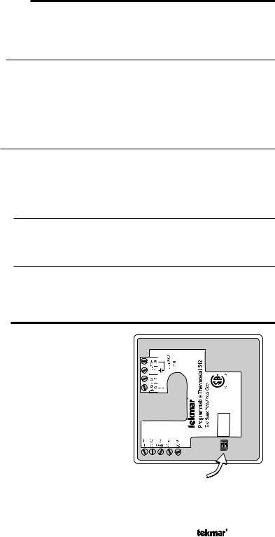
The tekmar Programmable Thermostat has two access levels. These access levels restrict the number of items available in the menus of the thermostat. The two access levels are User and Installer. This selection is made using the DIP switch located on the circuit board inside the thermostat.
The Installer access level allows the installer to adjust all of the settings in the thermostat including those required to match the thermostat to the mechanical system and the devices used.
The User access level allows the end user to adjust the time, temperatures and schedules used by the thermostat.
FCC Part 15
Canadian ICES
Meets Class B:
Made in Canada
|
|
|
|
|
|
|
|
|
|
|
|
938-02 |
512 |
|
|
|
|
|
|
|
|
|
|
|
|
||
|
|
|
|
|
|
|
|
|
|
SwitchSettings: Installer/User 2Stage/Heat-Cool |
Power: 24V±10%60Hz3VA |
Relay: 24V(ac)2A Class2 |
|
|
|
|
|
|
|
|
|
|
|
||||
|
|
|
|
|
|
|
|
|
|
|
|
|
|
|
|
|
|
|
|
|
|
|
|
|
|
|
|
|
|
|
|
|
|
|
|
|
|
|
|
|
|
Dip Switch
3 of 20 |
© 2009 |
D 512 - 09/09 |

TWO STAGE HEAT
The two stage mode of operation is selected using the DIP switch located on the circuit board inside the thermostat.
In cases where a one stage heating system can not provide sufficient heat under all conditions, a second stage of heat can be added to supplement the first stage. A two stage system therefore has one thermostat controlling two output relays.
Two Stage Logic
The temperature in a two stage zone is controlled by varying the on time of the Heat 1 and Heat 2 relays during a cycle. Under light loads, the Heat 1 relay is cycled on and off. As the load increases, the Heat 1 relay on time is increased until it reaches the maximum of the cycle length or, if a slab sensor is used, the slab temperature reaches the slab maximum setting. The Heat 2 relay is then cycled and its on time is increased as the load increases. When the heating load decreases, the on time of the Heat 2 relay is reduced until the Heat 2 relay is turned off completely. The thermostat then reduces the on time of the Heat 1 relay.
NOTE: When using a slab sensor, the Heat 2 relay may be on while the Heat 1 relay is off if the slab temperature has reached the slab maximum setting.
Air Sensor(s) Only Operation
When operating with only an air sensor, the on times for the Heat 1 and Heat 2 relays are calculated to satisfy the requirements of the air sensor.
Slab Sensor Only Operation
When operating with only a slab sensor, the on times for the Heat 1 and Heat 2 relays are calculated to satisfy the requirements of the slab sensor. The thermostat operates to maintain the slab at the minimum slab temperature setting.
NOTE: Operating with only a slab sensor can lead to either overheating or underheating of the space.
Air and Slab Sensor Operation
When operating with both air and slab sensors, the thermostat calculates an on time for the Heat 1 relay to satisfy the slab sensor’s requirements and on times for the Heat 1 and Heat 2 relays to satisfy the air sensor’s requirements. The thermostat operates the Heat 1 relay for the longer of these two on times.
While the minimum slab temperature is satisfied, the on times of the Heat 1 and Heat 2 relays are calculated to satisfy the air temperature requirements.
During heavy loads, the maximum slab temperature setting limits the on time of the Heat 1 relay. In this situation, the Heat 2 relay may be on while the Heat 1 relay is off.
NOTE: During light heating loads, overheating can occur due to the minimum slab temperature requirements.
Mode
Heat In the heat mode, the Heat 1 and Heat 2 relays are operated to satisfy the temperature requirement of the zone.
Off In the Off mode, the Heat 1 and Heat 2 relays are not operated.
NOTE: If an air or slab sensor is active in the Off mode, a freeze protection is enabled that allows the relays to be operated to keep the zone above 35°F (2°C).
© 2009 |
D 512 - 09/09 |
4 of 20 |

HEAT / COOL
The Heat / Cool mode of operation is selected using the DIP switch located on the circuit board inside the thermostat.
Air Sensor(s) Only Operation
When operating with only an air sensor, the on times of the Heat 1 relay and the Cool relay are calculated to satisfy the requirements of the air sensor.
Slab Sensor Only Operation
When operating with only a slab sensor, the on time of the Heat 1 relay is calculated to satisfy the requirements of the slab sensor. The thermostat operates to maintain the slab at the minimum slab temperature setting.
NOTE: When operating with only a slab sensor, the Cool relay does not operate. Operating with only a slab sensor can lead to either overheating or underheating of the space.
Air and Slab Sensor Operation
When operating with both air and slab sensors, the thermostat calculates an on time for the Heat 1 relay to satisfy the slab sensor’s requirements and an on time to satisfy the air sensor’s requirements. The Heat 1 relay operates for the longer of these two on times. The thermostat also calculates an on time for the Cool relay to satisfy the air sensor’s requirements. In this situation, heating and cooling can happen at the same time to prevent the space from overheating. This is most likely to occur when the slab is operating at the slab minimum temperature.
While the minimum slab temperature is satisfied, the Heat 1 relay on time is calculated to satisfy the air temperature setting. However, the maximum slab temperature setting limits the Heat 1 relay on time when the slab temperature becomes too warm. In this situation, underheating can occur in the space.
Mode
Auto In the Auto mode, the thermostat automatically switches between heating and cooling the space. However, the heating operation has priority over the cooling operation. In this mode, the minimum slab temperature is maintained even when the thermostat is cooling the air.
Heat In the Heat mode, the Heat 1 relay is operated to satisfy the heating temperature requirement of the zone and cooling is disabled.
Cool In the Cool mode, the Cool relay is operated to satisfy the cooling temperature requirement of the zone and heating is disabled. If a slab sensor is used, the slab minimum is ignored.
Off In the Off mode, the Heat 1 and Cool relays are not operated.
NOTE: If an air or slab sensor is active in the Off mode, a freeze protection is enabled that allows the Heat 1 relay to be operated to keep the zone above 35°F (2°C).
5 of 20 |
© 2009 |
D 512 - 09/09 |
Heating / Cooling Interlock
Time Interlock
In order to prevent frequent changes between heating and cooling, the thermostat has a Cooling Interlock setting. Once the Heat 1 relay has been off for a minimum of one heating cycle or the length of the Cooling Interlock, (whichever is longer) cooling is permitted.
Temperature Interlock
When in the Auto mode, the cooling temperature is limited to 3°F (1.5°C) above the heating temperature. If the cooling temperature is set below the heating temperature, the thermostat automatically adjusts the cooling setpoint.
When operating in the Cool mode, there is no interlock between the heating and cooling temperature.
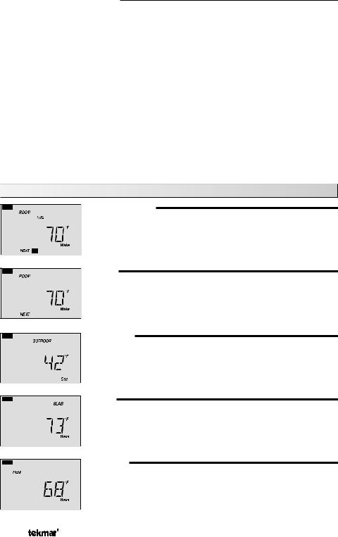
View Menu (1 of 1)
ROOM TARGET
The current desired air temperature for the space. This item is only available in the Installer access level.
(Must have an active air sensor.)
ROOM
The current air temperature for the space.
(Must have at least one active air sensor. This is the average of all active air sensors.)
OUTDOOR
The current temperature at the outdoor sensor .
(Sens 2 must be set to Out.)
SLAB
The current slab temperature.
(Must have an active slab sensor. If two slab sensors are present, this is the average temperature.)
The MIN segment is displayed when running on Min.
REMOTE
The current temperature at the remote sensor.
(Sens 1 must be set to Rem.)
© 2009 |
D 512 - 09/09 |
6 of 20 |
 Loading...