


- Data Brochure |
|
D 360 |
Mixing Control 360 |
|
03/09 |
|
|
|
The Mixing Control 360 is designed to control the supply water temperature to a hydronic system in order to provide outdoor reset or setpoint operation. The control uses a floating action mixing valve to regulate the supply water temperature, while protecting the boiler against flue gas condensation. The control has a Liquid Crystal Display (LCD) to view system status and operating information.
Additional Functions Include:
•Quick Setup for easy installation and programming of control
•User comfort adjustment to increase or decrease building space temperature
•Advanced settings to fine-tune building requirements
•Boiler Control for improved energy savings
•Powered mixing system pump output
•Optional indoor sensor for room air temperature control
•Test sequence to ensure proper component operation
•Setback input for energy savings
•120 V (ac) power supply
•CSA C US certified (approved to applicable UL standards)
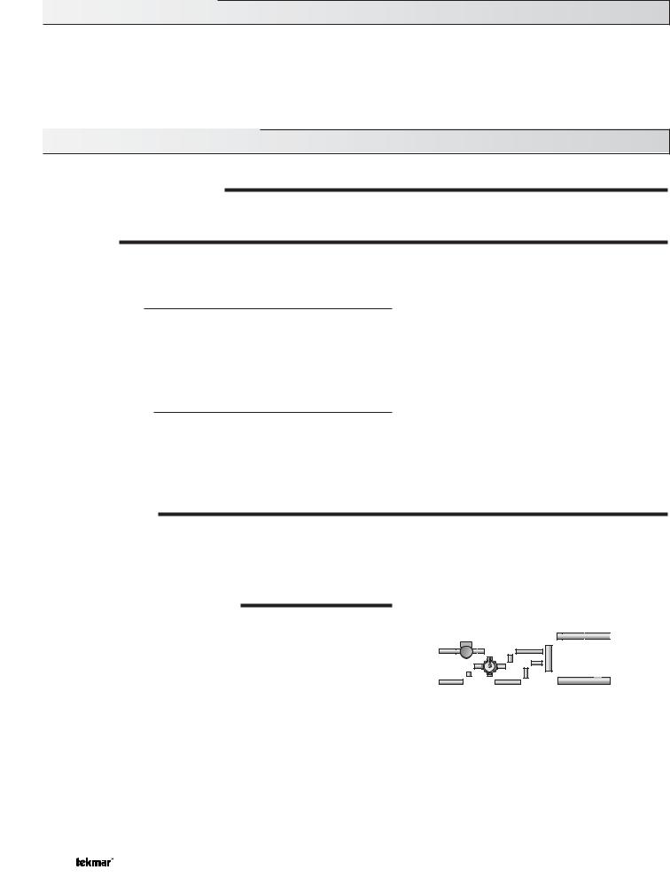
Terminal |
Motor |
Open Close Mixing |
Unit |
Speed |
Demand |
To increase or decrease the building temperature:
•Press the Item,  ,
,  buttons simultaneously for 1 sec. to enter the ADJUST menu
•Use the,  ,
,  buttons to adjust the ROOM setting
Display defaults back to VIEW menu after 20 sec.
Installer Instructions
 ROOM - Set to desired room temp.
OUTDR DSGN - Set to coldest (design) outdoor temp.
Terminal Unit |
Set to |
Item
Mixing Control 360
Floating Action
|
|
|
|
|
|
|
|
|
|
|
|
|
|
|
|
|
Powered Output |
||
1 |
|
2 |
3 |
4 |
5 |
|
6 |
|
|
|
7 |
8 |
|
9 |
10 |
11 |
|||
Mixing |
|
Power |
Sys |
|
|
|
|
|
Boiler |
R |
R |
C |
|||||||
Demand |
L |
N |
Pmp |
N |
|
|
|
|
|
|
|
|
Opn |
Cls |
|
||||
|
|
|
|
|
|
|
|
|
|
|
|
|
|
|
|
|
|
|
|
Note:
Mixing demand must be powered with 20 to 260 V (ac) before the boiler is able to fire.
Input
Mixing Demand
Signal
Input
120 V (ac) Power
Supply
|
|
|
|
|
|
|
High Mass Radiant ------- |
1 |
|
|
||
|
|
|
|
|
|
|
Low Mass Radiant ------- |
2 |
|
|
||
|
|
|
|
|
|
|
Fan Coil |
------------------ |
3 |
|
|
|
|
|
|
|
|
|
|
Convector ---------------- |
4 |
|
|
||
|
|
|
|
|
|
|
Radiator |
------------------ |
5 |
|
|
|
|
|
|
|
|
|
|
Baseboard --------------- |
6 |
|
|
||
|
|
Test |
|
Refer to brochure for more information |
|
|
||||||
|
|
|
|
|
|
|
|
|
||||
|
|
Made in Canada by |
|
|
|
|
Meets Class B: |
|
||||
|
|
|
|
|
|
Canadian ICES |
|
|||||
|
|
tekmar Control Systems Ltd. |
|
|
||||||||
|
|
|
FCC Part 15 |
|
|
|||||||
|
|
tektra 912-02 |
|
|
|
|
|
|
||||
|
|
|
|
|
|
|
|
|
||||
|
|
Power: |
120 V 50/60 Hz 1300 VA |
|
Code |
|
||||||
|
|
Floating Output: |
24 V (ac) 0.34 A 8 VA |
|
|
|||||||
|
|
Relays: |
240 V (ac) 10 A 1/3 hp |
|
Date |
|
||||||
|
|
Demand: |
20 to 260 V (ac) 2 VA |
|
|
|||||||
|
|
|
|
|
||||||||
|
|
|
|
|
|
|
|
|
||||
|
Do not apply power |
|
|
|
|
|
|
|
||||
12 |
13 |
14 |
15 |
16 |
17 |
18 |
|
Signal wiring must be |
H1170E |
|
||
Sw |
Com |
Boil |
Mix |
Com |
Out |
Indr |
|
rated at least 300 V. |
|
|||
UnO |
|
|
|
|
|
|||||||
|
|
|
|
|
|
|
|
|
|
|
|
|
|
|
|
|
|
|
|
|
|
|
|
|
|
Input
Indoor Sensor
Optional
Input
Outdoor Sensor
Included
Output |
|
|
|
|
|
|
|
|
|
|
|
|
|
|
|
|
|
|
|
|
|
|
|
|
|
|
|
|
|
|
|
|
Output |
Input |
Input |
Input |
|||
|
|
|
|||||||
|
|
|
|||||||
Mixing System |
Output |
Mixing Valve & |
tekmar Timer |
Universal Sensor |
Universal Sensor |
||||
Pump |
Boiler |
Actuating Motor |
Optional |
Included |
Included |
||||
1 of 20 © 2009 


 D 360 - 03/09

How To Use The Data Brochure
This brochure is organized into four main sections. They are: 1) Sequence of Operation, 2) Installation, 3) Control Settings, and 4) Troubleshooting. The Sequence of Operation section has three sub-sections. We recommend reading Section A: General Operation of the Sequence of Operation, as this contains important information on the overall operation of the control. Then read the sub-sections that apply to your installation. For quick installation and setup of the control, refer to the Installation section, DIP Switch Settings section, followed by the Quick Setup section.
The Control Settings section (starting at DIP Switch Settings) of this brochure describes the various items that are adjusted and displayed by the control. The control functions of each adjustable item are described in the Sequence of Operation.
Table Of Contents
User Interface |
pg. 2 |
Quick Setup |
pg. 14 |
Description of Display Elements |
pg. 3 |
Control Settings |
pg. 15 |
Sequence of Operation |
pg. 4 |
View Menu |
pg. 15 |
Section A: General Operation |
pg. 4 |
Adjust Menu |
pg. 16 |
Section B: Mixing |
pg. 5 |
Testing and Troubleshooting |
pg. 17 |
Section C: Boiler Operation |
pg. 8 |
Error Messages |
pg. 19 |
Installation |
pg. 10 |
Technical Data |
pg. 20 |
DIP Switch Settings |
pg. 14 |
Limited Warranty |
pg. 20 |
Reference Material: Essay E 003 “Characterized Heating Curve and Reset Ratio”
Essay E 021 “Mixing Methods and Sizing of Variable Speed Injection Pumps”
User Interface
The 360 uses a Liquid Crystal Display (LCD) as the method of supplying information. You use the LCD in order to set up and monitor the operation of your system. The 360 has three push buttons (Item,  ,
,  ) for selecting, viewing, and adjusting settings. As you program your control, record your settings in the ADJUST menu table which is found in the second half of this brochure.
Item
The abbreviated name of the selected item will be displayed in the item field of the display. To view the next available item, press and release the Item button. Once you have reached the last available item, pressing and releasing the Item button will return the display to the first item.
Adjust
To make an adjustment to a setting in the control, press and hold simultaneously for 1 second all 3 buttons. The display will then show the word ADJUST in the top right corner. Then select the desired item using the Item button. Finally use the  and/or
  button to make the adjustment.
Item
Item
To exit the ADJUST menu, either select the ESC item and press the  or
or  button, or leave the adjustment buttons alone for 20 seconds.
When the Item button is pressed and held in the VIEW menu, the display scrolls through all the adjust items in both access levels.
Additional information can be gained by observing the status field and pointers of the LCD. The status field will indicate which of the control’s outputs are currently active. Most symbols in the status field are only visible when the VIEW menu is selected.
© 2009 |
D 360 - 03/09 |
2 of 20 |

Display
Symbol Description
|
|
|
|
|
|
|
|
|
|
|
|
|
|
|
|
|
|
|
|
|
|
|
|
|
|
|
|
|
|
|
|
|
|
|
|
|
|
|
|
|
|
|
|
|
|
|
|
|
|
|
|
|
|
|
|
|
|
|
|
|
|
|
|
|
|
|
|
|
|
|
|
|
|
|
|
|
|
|
|
|
|
|
|
|
|
|
|
|
|
|
|
|
|
|
|
|
|
|
|
|
|
|
|
|
|
|
|
|
|
|
|
|
|
|
|
|
|
|
|
|
|
|
|
|
|
|
|
|
|
|
|
|
|
|
|
|
|
|
|
|
|
|
|
|
|
|
|
|
|
|
|
|
|
|
|
|
|
|
|
|
|
|
|
|
|
|
|
|
|
|
|
|
|
|
|
|
|
|
|
|
|
|
|
|
|
|
|
|
|
|
|
|
|
|
|
|
|
|
|
|
|
|
|
|
|
|
|
|
|
|
|
|
|
|
|
|
|
|
|
|
|
|
|
|
|
|
|
|
3 of 20 |
© 2009 |
|
D 360 - 03/09 |
|||||
Sequence of Operation
Section A |
|
Section B |
|
Section C |
General |
|
Mixing |
|
Boiler |
Operation |
|
Page 5 - 8 |
|
Operation |
Page 4 - 5 |
|
|
|
Page 8 - 9 |
|
|
|
|
|
Section A: General Operation
POWERING UP THE CONTROL
When the Mixing Control 360 is powered up, the control displays the control type number in the LCD for 2 seconds. Next, the software version is displayed for 2 seconds. Finally, the control enters into the normal operating mode.
OPERATION
The 360 uses a floating action mixing valve to vary the supply water temperature to a hydronic system. The supply water temperature is based on either the current outdoor temperature, or a fixed setpoint.
Outdoor Reset
When the outdoor design (OUTDR DSGN) setting is not set to OFF, the 360 calculates a mixing supply water temperature based on the outdoor air temperature. The 360 uses a Characterized Heating Curve and optionally indoor temperature feedback from an indoor sensor in this calculation.
Setpoint Control
When the outdoor design (OUTDR DSGN) setting is set to OFF, the 360 supplies a fixed mixing supply temperature equal to the MIX TARGET setting. An outdoor sensor is not required during this mode of operation.
|
Design Supply |
|
Terminal Unit |
TemperatureWaterIncreasing |
|
Indoor Design |
||
Outdoor Design |
||
Decreasing Outdoor Temperature |
||
FLOATING ACTION
A 24 V (ac) floating action actuator motor is connected directly to the 360 on the R Opn, R Cls, and C terminals (9,10 and 11). The 360 pulses the actuator motor open or close to maintain the correct mixed supply water temperature at the mix sensor when there is a mixing demand. The mixing valve that the actuator is connected to can be either a 2-way, 3-way, or 4-way valve. A visual indication as to whether the control is currently opening or closing the mixing valve is displayed in the LCD.
BOILER PROTECTION (BOIL MIN)
The 360 is capable of providing boiler protection from cold mixing system return water temperatures. If the boiler sensor temperature is cooler than the BOIL MIN setting while the boiler is firing, the 360 reduces the output to the mixing valve. This limits the amount of cool return water to the boiler and allows the boiler temperature to recover. This feature can only be used if a boiler sensor is installed.
Boiler Supply
Sensor
Mixing
Sensor
OR
Boiler Return 
Sensor
© 2009 |
D 360 - 03/09 |
4 of 20 |

EXERCISING
The 360 has a built-in exercising function. If the system pump or valve has not been operated at least once every 3 days, the control turns on the output for a minimum of 10 seconds. This minimizes the possibility of a pump or valve seizing during a long period of inactivity. The 360 ensures that the mixing valve operates over its entire range at least once each exercising period. While the control is exercising the Test LED flashes.
Note: The exercising function does not work if power to the control, pump, or valve is disconnected.
SETBACK (UNOCCUPIED)
To provide greater energy savings, the 360 has a setback capability. With setback, the supply water temperature in the system is reduced when the building is unoccupied. By reducing the supply water temperature, air temperature in the space may be reduced even when thermostat(s)are not turned down. Any time the UnO Sw (12)and the Com (13) terminals are shorted together, the control operates in the unoccupied (Night) mode. When in the unoccupied (Night) mode, the UNOCC segment is displayed in the LCD. The 360 adjusts the supply water temperature based on the UNOCC settings made in the control. This feature has no effect when the control is used as a setpoint control.
12 |
|
13 |
|
||
UnO |
|
Com |
Sw |
|
|

 Timer Switch
FACTORY DEFAULTS
The control comes preset with several factory defaults. These defaults are based on the terminal unit selection (see section B2). To fine-tune building requirements, these defaults may be changed. If a factory default value for a terminal unit is changed, the terminal unit number will flash when selected in the ADJUST menu.
To reload the factory defaults listed in section B2, power down the control and wait for 10 seconds. Power up the control while simultaneously holding the Item and buttons. The terminal unit number should now be displayed constantly in the LCD rather than flashing.
Section B: Mixing
Section B1 |
|
Section B2 |
|
Section B3 |
General |
|
Installer |
|
Advanced |
|
|
|
|
|
Section B1: General
MIXING DEMAND
A mixing demand is required in order for the 360 to provide heat. A mixing demand is generated by applying a voltage between 24 and 240 V (ac)across the Mixing Demand terminals (1 and 2).Once voltage is applied, the Mixing Demand pointer is displayed in the LCD. If the 360 is not in WWSD, the 360 closes the Sys Pmp contact. The 360 calculates a MIX TARGET supply temperature based on the outdoor air temperature and settings. If required, the 360 operates the boiler in order to provide heat to the mixing valve.
1 |
2 |
Mixing |
|
Demand |
|
24 to 240 V (ac)
SYSTEM PUMP OPERATION (SYS PMP)
The system pump contact (Sys Pmp, terminal 5) closes whenever there is a mixing demand and the 360 is not in WWSD. The system pump segment is displayed in the LCD. After the mixing demand has been satisfied, the 360 continues to operate the system pump for 20 seconds. This allows some residual heat to be purged out to the heating system. During WWSD, the system pump is operated based on the exercise function.
5 of 20 |
© 2009 |
D 360 - 03/09 |

INDOOR SENSOR
An indoor sensor may be used in order to provide indoor temperature feedback. The indoor sensor is connected to the Com and Indr terminals (16 and 18). In addition, power must be applied to the Mixing Demand terminals (1 and 2) as described in the MIXING DEMAND section. With the indoor sensor connected, the 360 is able to sense the actual room temperature. Indoor temperature feedback fine-tunes the supply water temperature in the mixing system to maintain room temperature. To adjust the room temperature, use the ROOM OCC or ROOM UNOCC setting in the ADJUST menu at the control.
If a multiple zone system is used with an indoor sensor, proper placement of the indoor sensor is essential. The indoor sensor should be located in an area which best represents the average air temperature of the zones.
CHARACTERIZED HEATING CURVE
When used as a mixing reset control, the 360 varies the supply water temperature based on the outdoor air temperature. The control takes into account the type of terminal unit that the system is using. Since different types of terminal units transfer heat to a space using different proportions of radiation, convection and conduction, the supply water temperature must be controlled differently. Once the control is told what type of terminal unit is used, the control varies the supply water temperature according to the type of terminal unit. This improves the control of the air temperature in the building.
MIXING TARGET TEMPERATURE (MIX TARGET)
When used as a mixing reset control, the MIX TARGET temperature is calculated from the Characterized Heating Curve settings, outdoor air temperature and optionally, indoor air temperature. When used as a setpoint control, the installer sets the MIX TARGET temperature. The control displays the temperature that it is currently trying to maintain as the mixing supply temperature. If the control does not have a mixing demand,”- - -” is displayed as the MIX TARGET.
Section B2: Installer
OUTDOOR DESIGN (OUTDR DSGN)
The OUTDR DSGN is the outdoor air temperature that is the typical coldest temperature of the year where the building is located. This temperature is used when doing the heat loss calculations for the building. If a cold outdoor design temperature is selected, the mixing supply temperature rises gradually as the outdoor temperature drops. If a warm outdoor design temperature is selected, the mixing supply temperature rises rapidly as the outdoor temperature drops.
SETPOINT OPERATION (MIX TARGET)
MIX DSGN |
|
|
|
Cold |
Temperature |
|
OUTDR |
|
|
Water |
|
|
DSGN |
|
|
|
|
MIX INDR |
Warm |
Increasing |
|
||
|
|
Decreasing Outdoor Temperature
For setpoint control, set the OUTDR DSGN to OFF. The MIX TARGET becomes the setpoint supply temperature that the control is to maintain. The MIX TARGET temperature is set by the installer in the ADJUST menu. An outdoor sensor is not required during this mode of operation.
ROOM OCC & UNOCC (ROOM)
The ROOM is the desired room temperature for the mixing zones, and it provides a parallel shift of the Characterized Heating Curve. The room temperature desired by the occupants is often different from the design indoor temperature (MIX INDR). If the room temperature is not correct, adjusting the ROOM setting increases or decreases the amount of heat available to the building. A ROOM setting is available for both the occupied (Day) and unoccupied (Night) modes.
|
|
|
|
|
|
re |
|
|
||
|
|
|
|
|
|
tu |
|
|
|
|
|
|
|
|
|
a |
|
|
|
||
|
|
|
|
|
r |
|
|
|
|
|
|
|
|
|
|
e |
|
|
|
|
|
|
|
|
|
|
p |
|
|
|
|
|
|
|
|
|
|
m |
|
|
|
|
|
|
|
|
|
e |
|
|
|
|
||
|
|
|
T |
|
|
|
|
|
||
|
|
l |
|
|
|
|
n |
|
||
|
a |
|
|
|
|
|
|
|||
|
tu |
|
|
|
|
|
|
ig |
Temperature |
|
|
|
|
|
|
|
|
s |
|||
A |
c |
|
|
|
|
|
|
e |
||
|
|
|
|
|
|
D |
||||
|
|
|
|
|
|
l |
||||
|
|
|
|
|
|
|
a |
|
||
|
|
|
|
|
|
|
rm |
|
||
|
|
|
|
|
|
N |
o |
|
||
|
|
|
|
|
|
|
|
|||
|
|
|
|
|
|
|
|
|
||
|
|
|
|
|
|
|
|
ROOM |
Water |
|
|
|
|
|
|
|
|
|
|
||
|
|
|
|
|
|
|
|
MIX INDR |
Increasing |
|
Decreasing Outdoor Temperature |
||||||||||
|
||||||||||
© 2009 |
D 360 - 03/09 |
6 of 20 |
 Loading...