


 Loading...
3-859-663-25(1)
Trinitron®
Color Video Monitor
Operating Instructions |
Page 2 |
||||||||||||
Mode d’emploi Page 20 |
|
||||||||||||
Manual de instrucciones |
Pá gina 38 |
||||||||||||
|
|
|
|
|
|
|
|
|
|
|
|
|
|
|
|
|
|
|
|
|
|
|
|
|
|
|
|
|
|
|
|
|
|
|
|
|
|
|
|
|
|
|
|
|
|
|
|
|
|
|
|
|
|
|
|
|
|
|
|
|
|
|
|
|
|
|
|
|
|
PVM-14M4U/14M4E/14M4A PVM-14M2U/14M2E/14M2A PVM-20M4U/20M4E/20M4A PVM-20M2U/20M2E
1996 by Sony Corporation

English
Owner’s Record
The model and serial numbers are located at the rear. Record these numbers in the spaces provided below. Refer to these numbers whenever you call upon your Sony dealer regarding this product.
Model No.
Serial No.
WARNING
To prevent fire or shock hazard, do not expose the unit to rain or moisture.
Dangerously high voltage are present inside the unit.
Do not open the cabinet. Refer servicing to qualified personnel only.
In the event of a malfunction or when maintenance is necessary, consult an authorized Sony dealer.
For the customers in the U.S.A.
This equipment has been tested and found to comply with the limits for a Class A digital device, pursuant to Part 15 of the FCC Rules. These limits are designed to provide reasonable protection against harmful interference when the equipment is operated in a commercial environment.
This equipment generates, uses, and can radiate radio frequency energy and, if not installed and used in accordance with the instruction manual, may cause harmful interference to radio communications. Operation of this equipment in a residential area is likely to cause harmful interference in which case the user will be required to correct the interference at his own expense.
You are cautioned that any changes or modifications not expressly approved in this manual could void your authority to operate this equipment.
For the customers in Europe
This product with the CE marking complies with both the EMC Directive (89/336/EEC) and the Low Voltage Directive (73/23/EEC) issued by the Commission of the European Community.
Compliance with these directives implies conformity to the following European standards:
•EN60950: Product Safety
•EN55103-1: Electromagnetic Interference (Emission)
•EN55103-2: Electromagnetic Susceptibility (Immunity)
This product is intended for use in the following Electromagnetic Environment(s):
E1 (residential), E2 (commercial and light industrial),
E3 (urban outdoors) and E4 (controlled EMC environment, ex. TV studio).
These products are designed for operation in the environments E1 to E4. During EMC stress, the performance (evaluated according to ITU/R 562-3 and ITU/R 500-4) may degrade as shown in Table 1. Without the EMC stress, all performance will recover to full function.
Table 1
|
Frequency |
Level |
|
|
|
|
|
14-inch Monitors |
24-50 MHz |
4-3 |
|
|
|
||
190-290, 360 and |
4 |
||
|
|||
|
420 MHz |
|
|
|
|
|
|
20-inch Monitors |
35-50 MHz |
1 |
|
|
|
||
100 and 420 MHz |
4 |
||
|
|||
|
|
|
For the customers in the United Kingdom
WARNING
THIS APPARATUS MUST BE EARTHED
IMPORTANT
The wires in this mains lead are coloured in accordance with the following code:
Green-and-yellow: Earth
Blue: Neutral Brown: Live
As the colours of the wires in the mains lead of this apparatus may not correspond with the coloured markings identifying the terminals in your plug proceed as follows:
The wire which is coloured green-and-yellow must be connected to the terminal in the plug which is marked by the letter E or by the safety earth symbol Y or coloured green or green-and-yellow.
The wire which is coloured blue must be connected to the terminal which is marked with the letter N or coloured black.
The wire which is coloured brown must be connected to the terminal which is marked with the letter L or coloured red.
Ensure that your equipment is connected correctly - If you are in any doubt consult a qualified electrician.
2

Precaution
On safety
•Operate the unit only with a power source as specified in “Specifications” section.
•The nameplate indicating operating voltage, power consumption, etc., is located at the rear.
•Should any solid object or liquid fall into the cabinet, unplug the unit and have it checked by qualified personnel before operating it any further.
•Do not drop or place heavy objects on the power cord. If the power cord is damaged, turn off the power immediately. It is dangerous to use the unit with a damaged power cord.
•Unplug the unit from the wall outlet if it is not to be used for several days or more.
•Disconnect the power cord from the AC outlet by grasping the plug, not by pulling the cord.
•The socket-outlet shall be installed near the equipment and shall be easily accessible.
On installation
•Allow adequate air circulation to prevent internal heat build-up.
Do not place the unit on surfaces (rugs, blankets, etc.) or near materials (curtains, draperies) that may block the ventilation holes.
•Do not install the unit in a location near heat sources such as radiators or air ducts, or in a place subject to direct sunlight, excessive dust, mechanical vibration or shock.
On cleaning
To keep the unit looking brand-new, periodically clean it with a mild detergent solution. Never use strong solvents such as thinner or benzine, or abrasive cleansers since they will damage the cabinet. As a safety precaution, unplug the unit before cleaning it.
On repacking
Do not throw away the carton and packing materials. They make an ideal container which to transport the unit. When shipping the unit to another location, repack it as illustrated on the carton.
If you have any questions about this unit, contact your authorized Sony dealer.
Table of Contents |
|
Features ..................................................................... |
4 |
Location and Function of Parts and Controls ....... |
6 |
Front ................................................................. |
6 |
Rear Panel ........................................................ |
8 |
Using On-Screen Menus ......................................... |
10 |
On-Screen Menu Configuration ..................... |
10 |
Operation through On-Screen Menus ............ |
11 |
Functions of On-Screen Menus ...................... |
12 |
Connections ............................................................. |
15 |
How to Connect the AC Power Cord ............. |
15 |
How to Connect a Cable to a |
|
BNC Connector ......................................... |
15 |
Specifications ........................................................... |
16 |
About this manual
Before operating the unit, please read this manual thoroughly and retain it for future reference.
The explanation given in this manual can be applied to the following models unless noted otherwise.
When explanation differs among models, this is clearly indicated in this manual.
•PVM-14M4U/14M4E/14M4A (14-inch monitor)
•PVM-14M2U/14M2E/14M2A (14-inch monitor)
•PVM-20M4U/20M4E/20M4A (20-inch monitor)
•PVM-20M2U/20M2E (20-inch monitor) Illustrations of the video monitor are of the PVM20M4U/20M4E/20M4A.
English
3

Features
Picture
HR (High Resolution) Trinitron 1) picture tube for PVM-14M4U/14M4E/14M4A/20M4U/20M4E/20M4A
HR Trinitron tube provides a high resolution picture. Horizontal resolution is more than 800 TV lines at the center of the picture.
Trinitron1) picture tube
for PVM-14M2U/14M2E/14M2A/20M2U/20M2E
Trinitron tube provides a high resolution picture. Horizontal resolution is more than 600 TV lines at the center of the picture.
Comb filter
When NTSC video signals are received, a comb filter activates to make more accurate Y/C separation. This contributes to less of a decrease in resolution, cross color and cross luminance phenomena.
Beam current feedback circuit
The built-in beam current feedback circuit assures stable white balance.
Four color system available
The monitor can display NTSC, PAL, SECAM and NTSC4.432) signals. The appropriate color system is selected automatically.
Blue only mode
In the blue only mode, an apparent monochrome display is obtained with all three cathodes driven with a blue signal. This facilitates color saturation and phase adjustments and observation of VCR noise.
Input
Analog RGB/component input connectors
Analog RGB or component (Y, R-Y and B-Y) signals from video equipment can be input through these connectors.
Y/C input connectors
The video signal, split into the chrominance signal (C) and the luminance signal (Y), can be input through this connector, eliminating the interference between the two signals, which tends to occur in a composite video signal, ensuring video quality.
External sync input
When the EXT SYNC selector is in the on position, the monitor can be operated on the sync signal supplied from an external sync generator.
Automatic termination (connector with  mark only)
The input connector is terminated at 75 ohms inside when no cable is connected to the loop-through output connector. When a cable is connected to an output connector, the 75-ohm termination is automatically released.
.......................................................................................................................................................................................................................................
1)“Trinitron” is a registered trademark of Sony Corporation.
2)The NTSC4.43 system refers to an NTSC color system in which the subcarrier frequency is modified to 4.43MHz. When an NTSC recorded video program is played back with a Trident (PAL/SECAM/NTSC4.43) VTR, the NTSC4.43 signal is output.
4
Functions
Underscan mode
The signal normally scanned outside of the screen can be monitored in the underscan mode.
Note
When the monitor is in the underscan mode, the dark RGB scanning lines may appear on the top edge of the screen. These are caused by an internal test signal, rather than the input signal.
Horizontal/vertical delay mode
The horizontal and vertical sync signals can be checked simultaneously in the H/V delay mode.
Auto/manual degaussing
Degaussing of the screen can be performed automatically when the power is turned on, or manually by pressing the DEGAUSS button.
You can set the delay time of auto degaussing to start working after the power is turned on. (DEGAUSS DELAY menu)
On-screen menus
You can set color temperature, CHROMA SET UP, and other settings by using the on-screen menus.
Five menu languages
You can select the menu language from among five languages on the menu.
SDI (Serial Digital Interface) Kit
By using the following optional SDI Kits, the monitor can display SMPTE 259M 4:2:2 serial digital signal from a digital VCR. (ex. Sony 4:2:2 VCR)
–BKM-101C: Component SDI Kit (for video)
–BKM-102: Component SDI Kit (for audio)
Note
When the serial number of the BKM-101C you want to connect is less than 2,010,000, an optional connecting harness (part no. 1-900-230-35) will be required.
Serial Remote Interface Kit
By using the optional BKM-103 Serial Remote Interface Kit, the monitor can be controlled from personal computers via the RS-422A serial interface.
EIA 19-inch rack mount kit available
Use a suitable kit when rack mounting.
Europe |
MB-502C (14-inches) / |
|
SLR-103C (20-inches) |
|
|
Any other area |
MB-502B (14-inches) / |
|
SLR-103A (20-inches) |
ATTENTION – When the product is installed in
arack:
a)Elevated operating ambient temperature
If installed in a closed or multi-unit rack assembly, the operating ambient temperature of the rack environment may be greater than room ambient. Therefore, consideration should be given to installing the equipment in an environment compatible with the manufacturer’s maximum rated ambient temperature (Tmra).
b)Reduced air flow
Installation of the equipment in a rack should be such that the amount of air flow required for safe operation of the equipment is not compromised.
c)Mechanical loading
Mounting of the equipment in the rack should be such that a hazardous condition is not achieved due to uneven mechanical loading.
d)Circuit overloading
Consideration should be given to the connection of the equipment to the supply circuit and the effect that overloading of circuits might have on overcurrent protection and supply wiring. Appropriate consideration of equipment nameplate ratings should be used when addressing this concern.
e)Reliable earthing
Reliable earthing of rack-mounted equipment should be maintained. Particular attention should be given to supply connections other than direct connections to the branch circuit (e.g., use of power strips).
5
Location and Function of Parts and Controls
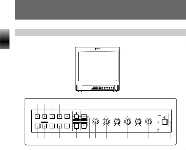
Front
1
@™ |
@¡ |
@º |
!ª |
!• |
A/ |
B/ |
C/ |
LINE/ |
EXT |
RGB |
COMPONENT |
SDI |
RGB |
SYNC |
|
RESET |
|
|
|
DEGAUSS BLUE |
UNDER |
H/V |
16:9 |
|
|
ONLY |
SCAN |
DELAY |
|
MENU |
BRIGHT |
CHROMA PHASE CONTRAST |
VOLUME |
|
APERTURE |
POWER |
|||
|
|
|
|
|
E X I T |
|
|
|
|
SELECT |
|
|
|
|
MIN MAX |
– + |
MIN MAX PUR GRN MIN MAX |
MIN MAX |
|
ENTER |
|
|
|
REMOTE |
!¶ !§ !∞ !¢ !£ !™ !¡ !º 9 8 7 6 5 4 3 2
1 Tally lamp
Lights up when the video camera connected to this monitor is selected, indicating that the picture is being recorded.
For details on how to light the tally lamp, see page 19.
2 POWER switch and indicator
Depress to turn on the monitor. The indicator will light green.
3 REMOTE indicator
Lights up when you select ON on the USER PRESET menu (see page 13), or when you connect a supplied cable to the REMOTE connector. The controls on the front panel do not work when this indicator lights up.
For details on how to connect the cable, see page 19.
4 VOLUME control
Turn this control clockwise or counterclockwise to obtain the desired volume.
5 CONTRAST control
Turn this control clockwise to make the contrast higher or counterclockwise to make it lower.
6 PHASE control
This control is effective only for the NTSC and NTSC4.43 color systems. Turn it clockwise to make the skin tones greenish or counterclockwise to make them purplish.
7 CHROMA control
Turn this control clockwise to increase the color intensity or counterclockwise to decrease it.
8 BRIGHT (brightness) control
Turn this control clockwise to increase the brightness or counterclockwise to decrease it.
9 APERTURE control
Turn this control clockwise to increase sharpness or counterclockwise to decrease sharpness.
6

Note
The PHASE (6), CHROMA (7) and APERTURE (9) controls have no effect on the pictures of RGB signals.
0 MENU (EXIT) button
Press this button to display the main menu.
When a menu is on the display, you can return to the previous menu by pressing this button.
!¡ ENTER (SELECT) button
Press the button to confirm a selected item on the menu.
!™ > (+)/ . (–) buttons
Press the buttons to move the cursor (z) or adjust selected item on the menu.
!£ 16:9 selector
Press this selector (light on) to monitor the signals of 16:9 picture.
!¢ H/V DELAY selector
Press this selector (light on) to observe the horizontal and vertical sync signals at the same time.
The horizontal sync signal is displayed in the left quarter of the screen; the vertical sync signal is displayed near the center of the screen.
!∞ UNDER SCAN selector
Press this selector (light on) for underscanning. The display size is reduced by approximately 5% so that four corners of the raster are visible.
!§ BLUE ONLY selector
RESET button
•As the BLUE ONLY selector, press this selector (light on) to eliminate the red and green signals. Only blue signal is displayed as an apparent monochrome picture on the screen. This facilitates “chroma” and “phase” adjustments and observation of VCR noise.
(“Phase” adjustment is effective only for the NTSC signals.)
•As the RESET button, you can reset the menu settings by pressing this button when a menu is on the display.
!¶ DEGAUSS button
Press this button momentarily. The screen will be demagnetized. Wait for 10 minutes or more before using this button again.
!• EXT SYNC (external sync) selector
•Set this selector to the off position (light off) to operate the monitor on the sync signal from the displayed video signal.
•Set this selector to the on position (light on) to operate the monitor on an external sync signal through the EXT SYNC connector.
!ª LINE/RGB input selector
Press this selector to select the input to be monitored.
•Set this selector to the off position (light off) to monitor the signal through the LINE A, LINE B or LINE C connectors.
•Set this selector to the on position (light on) to monitor the signal through the RGB/COMPONENT connectors.
@º C/SDI selector
•When the LINE/RGB input selector is set to the LINE position (light off), press this selector (light on) to monitor the signal through the LINE C connectors.
•When the LINE/RGB input selector is set to the RGB position (light on), press this selector (light on) to monitor the SDI signal (optional kits are required).
@¡ B/COMPONENT selector
•When the LINE/RGB input selector is set to the LINE position (light off), press this selector (light on) to monitor the signal through the LINE B connectors.
•When the LINE/RGB input selector is set to the RGB position (light on), press this selector (light on) to monitor the component signal through the RGB/ COMPONENT connectors.
@™ A/RGB selector
•When the LINE/RGB input selector is set to the LINE position (light off), press this selector (light on) to monitor the signal through the LINE A connectors.
•When the LINE/RGB input selector is set to the RGB position (light on), press this selector (light on) to monitor the RGB signal through the RGB/ COMPONENT connectors.
7
Location and Function of Parts and Controls
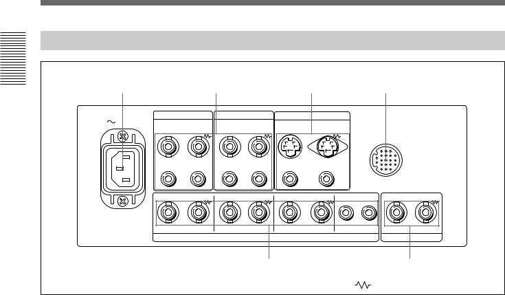
Rear Panel
1 |
|
2 |
|
|
3 |
|
|
4 |
|
AC IN |
LINE A |
|
LINE B |
|
LINE C |
|
|
|
|
VIDEO |
IN |
VIDEO |
IN |
VIDEO |
|
|
|
|
|
IN |
OUT |
OUT |
OUT |
|
REMOTE |
|
|||
|
|
|
|
|
|
|
|
||
IN |
AUDIO |
IN |
AUDIO |
IN |
AUDIO |
|
|
|
|
OUT |
OUT |
OUT |
|
|
|
|
|||
IN |
OUT |
IN |
OUT |
IN |
OUT |
IN |
OUT |
IN |
OUT |
|
R/R–Y |
|
G/Y |
|
B/B–Y |
AUDIO |
|
|
|
|
|
|
RGB/COMPONENT |
|
|
|
EXT SYNC |
||
|
|
|
5 |
|
|
|
|
|
6 |
|
|
|
|
|
|
(The |
mark indicates automatic termination.) |
||
1 AC IN socket
Connect the supplied AC power cord to this socket and to a wall outlet.
2 LINE A, LINE B connectors
Two groups (A and B) of line input connectors for the composite video and audio signals and their loopthrough output connectors.
To monitor the input signal through these connectors, set the LINE/RGB selector to the LINE position (light off) and press the A/RGB or B/COMPONENT selector (light on).
VIDEO IN (BNC)
Connect to the video output of video equipment, such as a VCR or a color video camera.
For a loop-through connection, connect to the video output of another monitor.
VIDEO OUT (BNC)
Loop-through output of the VIDEO IN connector. Connect to the video input of a VCR or another monitor.
When the cable is connected to this connector, the 75-ohm termination of the input is automatically released, and the signal input to the VIDEO IN connector is output from this connector.
AUDIO IN (phono jack)
Connect to the audio output of a VCR or to a microphone via a suitable microphone amplifier. For a loop-through connection, connect to the audio output of another monitor.
AUDIO OUT (phono jack)
Loop-through output of the AUDIO IN connector. Connect to the audio input of a VCR or another monitor.
3 LINE C connectors
Y/C IN (4-pin mini-DIN)
Connect to the Y/C separate output of a video camera, VCR or other video equipment.
For a loop-through connection, connect to the Y/C separate output of a VCR or another monitor.
Y/C OUT (4-pin mini-DIN)
Loop-through output of the Y/C IN connector. Connect to the Y/C separate input of a VCR or another monitor.
When the cable is connected to this connector, the 75ohm termination of the input is automatically released, and the signal input to the Y/C IN connector is output from this connector.
8

AUDIO IN (phono jack)
Connect to the audio output of a VCR or a microphone (via a suitable microphone amplifier).
AUDIO OUT (phono jack)
Loop-through output of the AUDIO IN connector. Connect to the audio input of a VCR or another monitor.
4 REMOTE connector (20-pin)
Connect to the tally output of a control console, special-effect generator, etc. The tally lamp on the front panel will be turned on and off by the connected equipment. This connector can also be used for connecting a remote control unit.
For details on the pin assignment of this connector, see page 19.
5 RGB/COMPONENT connectors
RGB signal or component signal input connectors and their loop-through output connectors.
To monitor the input signal through these connectors, set the LINE/RGB selector to the RGB position (light on), and press the A/RGB or B/COMPONENT selector (light on).
R/R-Y IN, G/Y IN, B/B-Y IN (BNC)
When the EXT SYNC selector is set to the off position (light off), the monitor operates on the sync signal from the G/Y channel.
To monitor the RGB signal
Connect to the analog RGB signal outputs of a video camera, etc.
To monitor the component signal
Connect to the R-Y/Y/B-Y component signal outputs of a Sony Betacam video camera, etc.
R/R-Y OUT, G/Y OUT, B/B-Y OUT (BNC)
Loop-through outputs of the R/R-Y IN, G/Y IN, B/B- Y IN connectors.
When the cables are connected to these connectors, the 75-ohm termination of the inputs is automatically released, and the signal inputs to the R/R-Y IN, G/Y IN, B/B-Y IN connectors are output from these connectors.
To output the RGB signal
Connect to the analog RGB signal inputs of a video printer or another monitor.
To output the component signal
Connect to the R-Y/Y/B-Y component signal inputs of a Betacam video recorder, etc.
AUDIO IN (phono jack)
Connect to the audio output of video equipment when the analog RGB or component signal is input.
AUDIO OUT (phono jack)
Loop-through outputs of the AUDIO IN connector.
6 EXT SYNC (external sync) connectors
Press the EXT SYNC selector (light on) to use the sync signal through this connector.
IN (BNC)
When this monitor operates on an external sync signal, connect the reference signal from a sync generator to this connector.
OUT (BNC)
Loop-through output of the IN connector. Connect to the external sync input of video equipment to be synchronized with this monitor.
When the cable is connected to this connector, the 75ohm termination of the input is automatically released, and the signal input to the IN connector is output from this connector.
9
Using On-Screen Menus
You can make various settings and adjustments of the monitor using the on-screen menus.
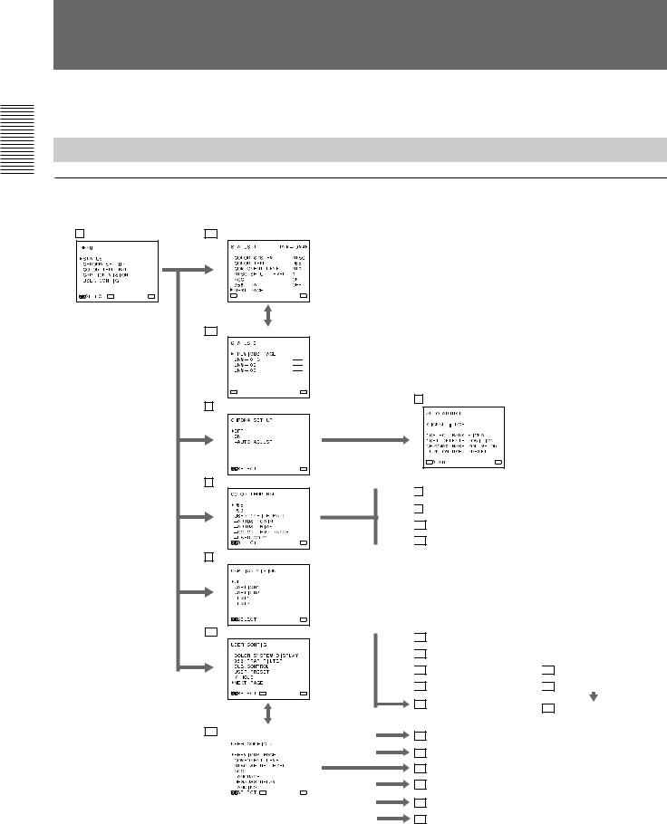
On-Screen Menu Configuration
On-screen menu tree-chart
1 Main menu |
2a STATUS 1 menu |
ENTER |
MENU |
ENTER |
MENU |
2b STATUS 2 menu
ENTER |
MENU |
3 CHROMA SET UP menu
MENU
4 COLOR TEMP/BAL menu
MENU
5 CAPTION VISION menu1)
MENU
6a USER CONFIG 1 menu
ENTER |
MENU |
For details on the menu type and each on-screen menu, see “Functions of On-Screen Menus” on page 12.
7 AUTO ADJUST screen
ENTER |
MENU |

 8 ADJUST GAIN screen

 9 ADJUST BIAS screen

 10 COLOR TEMP RANGE menu

 11 USER COPY menu

 12 COLOR SYSTEM DISPLAY menu

 13 358 TRAP FILTER menu

 14 SUB CONTROL menu
 15 SUB CONTROL screen

 16 USER PRESET menu
 17 PRESET ADJUST menu
19 V HOLD screen |
18 PRESET ADJUST screen |
|
6b USER CONFIG 2 menu |
|
20 COMPONENT LEVEL menu |
||
|
||||
|
|
|
|
21 NTSC SETUP LEVEL menu |
|
|
|
|
22 ACC menu |
|
|
|
|
23 LANGUAGE menu |
|
ENTER |
MENU |
|
|
|
|
|
|
24 DEGAUSS DELAY menu |
|
|
|
||
|
|
|
|
25 LANDING screen2) |
|
|
|
|
|
10
Operation through On-Screen Menus
Menu operation buttons
There are five menu operation buttons on the front panel of the monitor.
|
|
3 >/+ button |
1 MENU/EXIT |
|
|
|
|
|
button |
B/ |
C/ |
LINE/ |
EXT |
|
COMPONENT |
SDI |
RGB |
SYNC |
MENU |
|
|
|
|
E X I T |
RESET |
|
|
|
SELECT |
BLUE |
UNDER |
H/V |
16:9 |
ENTER |
ONLY |
SCAN |
DELAY |
|
|
|
|
|||
|
|
4 ./– button |
|
|
5 RESET button |
|
2 ENTER/ |
||
|
|
|
|
SELECT |
|
|
|
|
button |
The following table shows how these five buttons function when using the menus.
|
|
Button |
|
To select menu item |
|
|
|
To adjust the item selected |
|
|
|
|
|
|
1 |
|
MENU |
|
return to the previous menu |
|
|
|
||
|
EXIT |
|
return to the previous menu |
|
|
|
|
||
|
|
|
|
|
2 |
|
ENTER |
|
decide a selected item |
|
|
|
||
|
SELECT |
|
select an adjustment item |
|
|
|
|
||
|
|
|
|
|
3 |
> |
|
move the cursor (z) upwards |
|
|
|
|
|
|
+ |
|
increase selected value |
||
|
|
|||
|
|
|
|
|
4 |
. |
|
move the cursor (z) downwards |
|
|
|
|
|
|
|
– |
|
decrease selected value |
|
|
|
|
||
|
|
|
|
|
5 |
|
|
reset current settings to the factory |
|
RESET |
|
|||
|
setting |
|||
|
|
|
|
|
|
|
|
|
|
The buttons that can be used on the menus and adjustment screens are displayed at the bottom of the screen. You can perform menu operation using the displayed buttons.
Menu |
Adjustment screen |
ENTER |
MENU |
SELECT |
RESET |
EXIT |
Usable buttons Usable buttons
Display of the usable menu operation buttons
Operating procedures
To display the menu, follow this procedure.
1 Press the MENU/EXIT (1) button.
MENU (1 : main menu) appears.
2 Move the cursor (z) to the desired setting menu by pressing the ./– or >/+ (4, 3) button.
3 Press the ENTER/SELECT (2) button.
The setting menu selected in step 2 appears.
4 Move the cursor (z) to the desired item by pressing the ./– or >/+ (4, 3) button.
5 Press the ENTER/SELECT (2) button.
The adjustment screen or setting menu selected in step 4 appears.
For detailed information of menus, see “Functions of OnScreen Menus” on page 12.
...........................................................................................................................................................................................................................
1)5 CAPTION VISION menu is provided with PVM-14M4U/14M2U/20M4U/20M2U only.
2)@∞ LANDING screen is provided with PVM-20M4U/20M4E/20M4A only.
11
Using On-Screen Menus
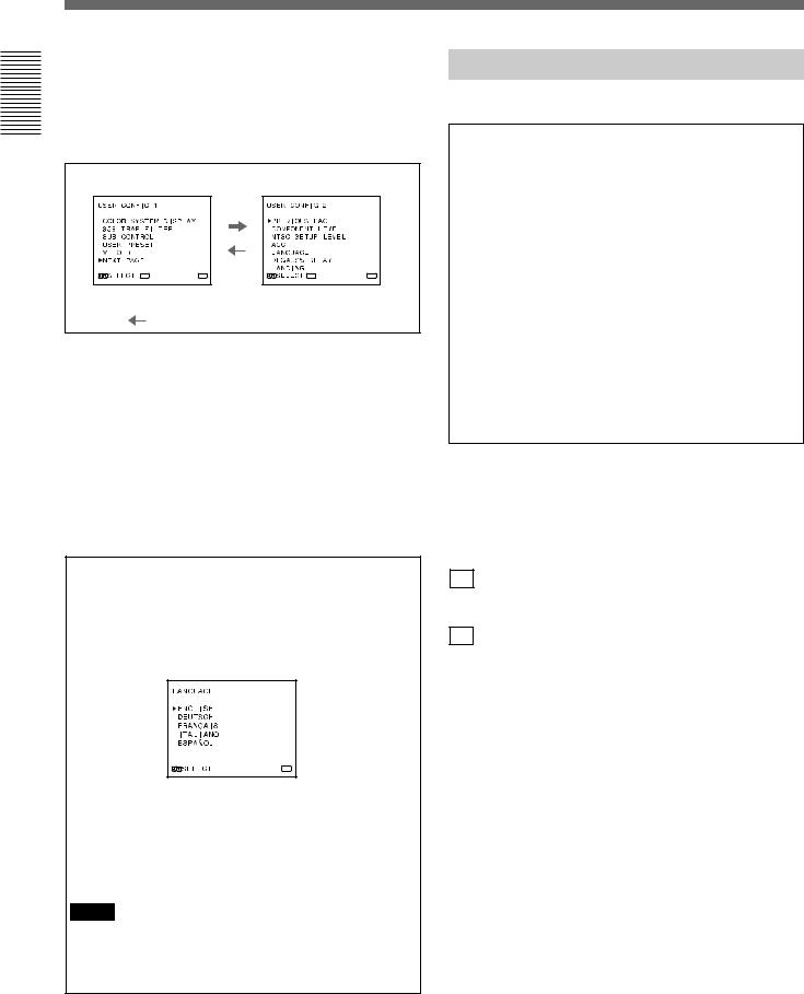
To display the next (or previous) page of the menus
Select NEXT PAGE on the menu to display the next page and PREVIOUS PAGE on the menu to display the previous page.
MENU 1 |
MENU 2 |
ENTER |
MENU |
ENTER |
MENU |
 : When selecting NEXT PAGE
: When selecting PREVIOUS PAGE
How to display the next or the previous page
To close the menu (to return to the regular screen)
Each time you press the MENU/EXIT (1) button, the on-screen menu returns to the one previously displayed. Press the MENU/EXIT (1) button repeatedly until the regular screen appears.
For PVM-14M4E/14M4A/14M2E/14M2A/ 20M4E/20M4A/20M2E:
For the first time when the monitor is turned on, the LANGUAGE menu (@£) will appear on the screen. So, select the language you want to use.
MENU
1 Move the cursor (z) to the desired language by pressing the ./– or >/+ (4, 3) button.
2 Press the MENU/EXIT (1) button.
Note
Unless you press the MENU/EXIT (1) button in the procedure above, the LANGUAGE menu will always appear whenever you turn on the monitor.
Functions of On-Screen Menus
There are four types of on-screen menus.
Main menu
You can enter another menu such as status menu or setting menu.
Status menu
You can confirm the current settings.
Setting menu
You can select an item or enter an adjustment screen on this menu by using the >/+, ./– and ENTER/SELECT buttons.
Adjustment screen
You can make adjustments on this screen. The adjustments you made remain unchanged until next change even if you turn off the power.
([ ] indicates the factory setting.)
1Main menu
Select another menu and press ENTER/SELECT to go to the menu.
2a STATUS 1 menu
Shows the current settings.
2b STATUS 2 menu
Shows what optional kit is installed in the monitor.
3CHROMA SET UP menu
Select ON on this menu to activate “chroma” and “phase” (NTSC signal only) adjustments done on the AUTO ADJUST screen (7). [OFF]
4COLOR TEMP/BAL menu
Select the color temperature from among D65, D93 and USER. USER is set to D65 as the factory setting. You can adjust or change the color temperature in USER mode (a measuring instrument is required).
[D65]
5CAPTION VISION menu
This menu is provided only for PVM-14M4U/14M2U/ 20M4U/20M2U.
The monitor can display the signal with Caption Vision. To display it, select the caption type in this menu. [OFF]
12
6a USER CONFIG 1 menu
Select an item to adjust on the menus and screens (!™ through !ª). To go to the USER CONFIG 2 menu, select NEXT PAGE.
6b USER CONFIG 2 menu
Select an item to adjust on the menus and screens (@º through @¢). To go to the USER CONFIG 1 menu select PREVIOUS PAGE.
7AUTO ADJUST screen
Select the color bar signal (full, SMPTE, EIA) and press ENTER/SELECT to start automatic “chroma” and “phase” (NTSC signal only) adjustments.
To activate these adjustments, select ON on the CHROMA SET UP menu (3).
8ADJUST GAIN screen
Adjust GAIN in USER mode.
9ADJUST BIAS screen
Adjust BIAS in USER mode.
!ºCOLOR TEMP RANGE menu
Select the color temperature range in USER mode. [5000K-10000K]
!¡USER COPY menu
Store the factory setting of D65 or D93 as the value for USER mode.
!™COLOR SYSTEM DISPLAY menu
Select the color system type. When AUTO is selected, the color system type being used appears on the screen each time you change the signal input. [AUTO]
!£358 TRAP FILTER menu
Color spill or color noise may be eliminated if you select ON (NTSC signal only).
Normally select OFF. [OFF]
!¢SUB CONTROL menu
Select an item (CONTRAST, BRIGHT, CHROMA and PHASE controls on the front panel) to finely adjust on the SUB CONTROL screen (!∞).
!∞SUB CONTROL screen
Finely adjust the selected item on the SUB CONTROL menu (!¢). Each control (CONTRAST, BRIGHT, CHROMA and PHASE control) has a click position at the center of its adjustment range. You can adjust the setting of the click position with this feature.
!§USER PRESET menu
If you select ON on this menu, the REMOTE indicator lights up and the controls on the front panel do not work. The monitor operates with the user preset settings.
To adjust the user preset settings, select the PRESET ADJUST menu (!¶). [OFF]
!¶PRESET ADJUST menu
You can preset the BRIGHT, CHROMA, PHASE, CONTRAST, VOLUME, and APERTURE controls to a desired level and can use these settings by selecting ON on the USER PRESET menu (!§).
!•PRESET ADJUST screen
Adjust the selected item (BRIGHT, CHROMA, PHASE, CONTRAST, VOLUME, and APERTURE control) on the PRESET ADJUST menu (!¶).
!ªV HOLD screen
Adjust the vertical hold if the picture rolls vertically. When you cannot read the display, select the input that is not connected.
@ºCOMPONENT LEVEL menu
Select the component level from among three modes.
N10/SMPTE |
for 100/0/100/0 signal |
BETA 7.5 |
for 100/7.5/75/7.5 signal |
BETA 0 |
for 100/0/75/0 signal |
For PVM-14M4U/14M2U/20M4U/20M2U
|
[BETA 7.5] |
For PVM-14M4E/14M4A/14M2E/14M2A/20M4E/ |
|
20M4A/20M2E |
[N10/SMPTE] |
13

Using On-Screen Menus
@¡NTSC SETUP LEVEL menu
Select the NTSC setup level from two modes.
The 7.5 setup level is mainly used in north America. The 0 setup level is mainly used in Europe.
For PVM-14M4U/14M2U/20M4U/20M2U |
[7.5] |
For PVM-14M4E/14M4A/14M2E/14M2A/20M4E/ |
|
20M4A/20M2E |
[0] |
@™ACC menu
Set ACC (Auto Color Control) circuit on or off. When the fine adjustment is necessary, select OFF on the ACC menu.
Normally select ON. [ON]
@£LANGUAGE menu
You can select the menu language from among five languages (English, German, French, Italian, Spanish).
[ENGLISH]
@¢DEGAUSS DELAY menu
Set the delay time of auto degaussing to start working after the power is turned on. The delay time can be set within 0 to 99 seconds. [0]
@∞LANDING screen
This menu is provided only for PVM-20M4U/20M4E/ 20M4A.
If the color is not uniform even after you press the DEGAUSS button, you can adjust the landing so as to obtain color uniformity on this screen.
The following two methods are available to adjust the landing.
When the signals of the horizontal lines are input and displayed:
Press the ./– or >/+ button until the lines are displayed on the screen as horizontally as possible.
When the signals of the white color are input and displayed:
Press the ./– or >/+ button until the white color on the screen become as uniform as possible.
To reset the setting to standard (00), press the RESET button.
14

Connections
How to Connect the AC Power Cord
Connect the AC power cord (supplied) to the AC IN socket and to a wall outlet.
To remove the AC power cord
Pull out the AC plug holder while pressing the lock levers.
to AC IN
to a wall outlet
To connect an AC power cord securely with an AC plug holder
1 |
AC IN socket |
|
AC power plug
AC plug holder
Plug the power cord into the AC IN socket. Then, attach the AC plug holder (supplied) on top of the AC power cord.
2
Lock levers
Slide the AC plug holder over the cord until it locks.
How to Connect a Cable to a BNC Connector
Connect a coaxial cable with the BNC plugs to the BNC connectors on the rear panel as illustrated below.
Insert the BNC plug into the connector on the rear panel, matching the slit and pin, and turn the BNC plug clockwise to secure the connection.
15

Specifications
Video signal
For PVM-14M4U/14M4E/14M4A/20M4U/20M4E/ 20M4A:
Color system |
NTSC, PAL, SECAM, NTSC4.43 |
Resolution |
800 TV lines |
Aperture correction |
0 dB to +6 dB |
Frequency response |
|
LINE |
10 MHz ± 3 dB (Y signal) |
RGB |
10 MHz ± 3 dB |
Synchronization |
AFC time constant 1.0 msec. |
For PVM-14M2U/14M2E/14M2A/20M2U/20M2E:
Color system |
NTSC, PAL, SECAM, NTSC4.43 |
Resolution |
600 TV lines |
Aperture correction |
0 dB to +6 dB |
Frequency response |
|
LINE |
10 MHz ± 3 dB (Y signal) |
RGB |
10 MHz ± 3 dB |
Synchronization |
AFC time constant 1.0 msec. |
Picture performance
For PVM-14M4U/14M4E/14M4A/14M2U/14M2E/ 14M2A:
Normal scan |
7 % over scan of CRT effective screen |
|
area |
Under scan |
5 % underscan of CRT effective screen |
|
area |
H. linearity |
Less than 4.0 % (typical) |
V. linearity |
Less than 4.0 % (typical) |
Convergence |
|
Central area: |
Less than 0.4 mm (typical) |
Peripheral area: |
Less than 0.5 mm (typical) |
Raster size stability |
H: 1.0%, V: 1.5% |
High voltage regulation |
|
|
3.5 % |
Color temperature |
D65/D93, selectable |
|
USER (3,200K–10,000K, factory |
|
setting is D65) |
For PVM-20M4U/20M4E/20M4A:
Normal scan |
7 % over scan of CRT effective screen |
|
area |
Under scan |
5 % underscan of CRT effective screen |
|
area |
H. linearity |
Less than 5.0 % (typical) |
V. linearity |
Less than 5.0 % (typical) |
Convergence |
|
Central area: |
Less than 0.5 mm (typical) |
Peripheral area: |
Less than 0.7 mm (typical) |
Raster size stability |
H: 1.0%, V: 1.5% |
High voltage regulation |
|
|
4.0 % |
Color temperature |
D65/D93, selectable |
|
USER (3,200K–10,000K, factory |
|
setting is D65) |
For PVM-20M2U/20M2E
Normal scan |
7 % over scan of CRT effective screen |
|
area |
Under scan |
5 % underscan of CRT effective screen |
|
area |
H. linearity |
Less than 5.0 % (typical) |
V. linearity |
Less than 5.0 % (typical) |
Convergence |
|
Central area: |
Less than 0.6 mm (typical) |
Peripheral area: |
Less than 1.0 mm (typical) |
Raster size stability |
H: 1.0%, V: 1.5% |
High voltage regulation |
|
|
4.0 % |
Color temperature |
D65/D93, selectable |
|
USER (3,200K–10,000K, factory |
|
setting is D65) |
16

Inputs (common to all models)
LINE A/B |
BNC connector (× 2), 1Vp-p ±6 dB, |
VIDEO IN |
|
|
sync negative |
AUDIO IN |
Phono jack (× 2), –5 dBua), more than |
|
47 kilo-ohms |
LINE C |
4-pin mini-DIN (×1) |
Y/C IN |
|
|
See the pin assignment on page 19. |
AUDIO IN |
Phono jack (× 1), –5 dBua), more than |
47 kilo-ohms RGB/COMPONENT
R/R-Y,G/Y,B/B-Y IN: BNC connector (× 3) R, G, B channels: 0.7 Vp-p, ±6 dB
Sync on green: 0.3 Vp-p, negative R-Y, B-Y channels: 0.7 Vp-p, ±6 dB
Y channel: 0.7 Vp-p, ±6 dB
|
(Standard color bar signal of 75% |
|
chrominance) |
AUDIO IN |
Phono jack (× 1), –5 dBua), more than |
|
47 kilo-ohms |
EXT SYNC IN |
BNC connector (× 1) |
|
4 Vp-p, ±6 dB, sync negative |
REMOTE |
20-pin connector (× 1) |
|
See the pin assignment on page 19. |
a) 0 dBu = 0.775 Vr.m.s.
Outputs (common to all models)
LINE A/B VIDEO OUT
AUDIO OUT
LINE C
Y/C OUT
AUDIO OUT
RGB/COMPONENT
R/R-Y,G/Y,B/B-Y OUT: BNC connector (× 3)
|
loop-through |
|
Automatic 75 ohms termination |
AUDIO OUT |
Phono jack (× 1) loop-through |
EXT SYNC OUT |
BNC connector (× 1) |
|
Automatic 75 ohms termination |
Speaker output |
Output level: 0.8 W |
General
For PVM-14M4U:
CRT |
SMPTE-C phosphor |
|
Power consumption |
90 W (with SDI: 99 W) |
|
Power requirements |
120 V AC, 50/60Hz, 1.0 A |
|
Dimensions (w/h/d) |
Approx. 346 × |
340 × 431 mm |
|
(135⁄8 × 131⁄2 × |
17 inches) |
|
not incl. projecting parts and controls |
|
Mass |
Approx. 16.7kg (36 lb 13 oz) |
|
Accessory supplied |
AC power cord (1) |
|
|
AC plug holder (1) |
|
|
Tally label (1) |
|
|
Cable with a 20-pin connector (1) |
|
For PVM-14M4E/14M4A:
CRT EBU phosphor
Power consumption 90 W (with SDI: 99 W)
Power requirements 100 to 240 V AC, 50/60Hz, 1.2–0.5 A Peak inrush current
(1)Power ON, current probe method: 18 A (240 V)
(2)Hot switching inrush current, measured in accordance with European standard EN55103-1: 4 A (230 V)
Dimensions (w/h/d) |
Approx. 346 × |
340 × 431 mm |
|
(135⁄8 × 131⁄2 × |
17 inches) |
|
not incl. projecting parts and controls |
|
Mass |
Approx. 16.7kg (36 lb 13 oz) |
|
Accessory supplied |
AC power cord (1) |
|
|
AC plug holder (1) |
|
|
Tally label (1) |
|
|
Cable with a 20-pin connector (1) |
|
For PVM-14M2U:
CRT |
P-22 phosphor |
|
Power consumption |
90 W (with SDI: 99 W) |
|
Power requirements |
120 V AC, 50/60Hz, 1.0 A |
|
Dimensions (w/h/d) |
Approx. 346 × |
340 × 431 mm |
|
(135⁄8 × 131⁄2 × |
17 inches) |
|
not incl. projecting parts and controls |
|
Mass |
Approx. 16.7kg (36 lb 13 oz) |
|
Accessory supplied |
AC power cord (1) |
|
|
AC plug holder (1) |
|
|
Tally label (1) |
|
|
Cable with a 20-pin connector (1) |
|
17
Loading...