


Working Instruction, Mechanical
Working Instruction, Mechanical
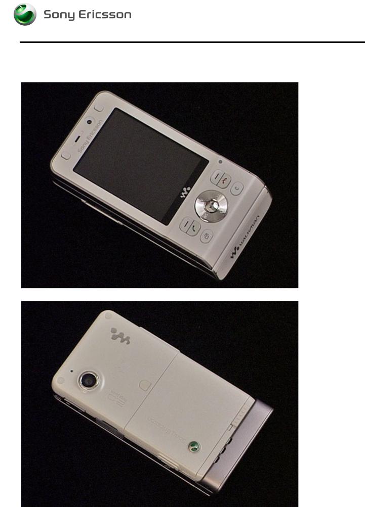
Applicable for W910
CONTENTS
1 Introduction .............................................................................. |
3 |
|
1.1 |
Equipment................................................................................. |
4 |
1.2 |
General cautions ...................................................................... |
5 |
1.3 |
Adhesives ................................................................................. |
5 |
2 Disassembly ............................................................................. |
6 |
|
2.1 Overview ................................................................................... |
6 |
|
2.1.1 M2, Battery Cover and Battery .............................................. |
7 |
|
2.1.2 |
Rear Back Cover ................................................................... |
8 |
2.1.3 |
Main PCB ............................................................................ |
10 |
2.1.4 |
Front Cover Assembly......................................................... |
11 |
2.1.5 |
Navi Key PBA...................................................................... |
13 |
2.1.6 |
Display ................................................................................ |
13 |
3 Replacements......................................................................... |
14 |
|
3.1 |
Battery Cover.......................................................................... |
15 |
3.2 |
Battery ..................................................................................... |
15 |
3.3 |
RF Cap..................................................................................... |
15 |
3.4 |
Label Co-Brand Inlay ............................................................. |
15 |
3.5 |
Keyboard Main........................................................................ |
15 |
3.6 |
Liquid Intrusion Indicator...................................................... |
16 |
3.7 |
Panel Antenna ........................................................................ |
16 |
3.8 |
Rear Back Cover..................................................................... |
16 |
3.9 |
Key, On/Off.............................................................................. |
16 |
3.10 Key, Volume............................................................................ |
16 |
|
3.11 Key, Camera............................................................................ |
16 |
|
3.12 Key, Music............................................................................... |
17 |
|
3.13 Cap, MemoryStick .................................................................. |
17 |
|
3.14 Camera 2.0 MPixel CMOS...................................................... |
17 |
|
3.15 BT Antenna Assy.................................................................... |
17 |
|
3.16 Front Cover Assembly........................................................... |
18 |
|
3.17 Key, Game............................................................................... |
18 |
|
3.18 Key, Navi ................................................................................. |
18 |
|
3.19 Navi Key PBA.......................................................................... |
18 |
|
3.20 Display..................................................................................... |
18 |
|
3.21 Slider Flex Module.................................................................. |
18 |
|
3.22 Slider Sub Assembly.............................................................. |
18 |
|
3.23 Main Antenna.......................................................................... |
19 |
|
3/000 21-1/FEA 209 544/129 A |
|
1(34) |
Company Internal © Sony Ericsson Mobile Communications AB |
|
|

|
|
|
Working Instruction, Mechanical |
|
3.24 Speaker Flex Module.............................................................. |
22 |
|
|
3.25 Key Foil Assy.......................................................................... |
24 |
|
|
3.26 Camera QCIF MPixel CMOS .................................................. |
26 |
|
|
3.27 Receiver Flex Module............................................................. |
26 |
|
|
3.28 Label |
...................................................................................... |
27 |
4 |
Reassembly ............................................................................ |
28 |
|
|
4.1 Overview ................................................................................. |
28 |
|
|
4.1.1 |
Display ................................................................................ |
29 |
|
4.1.2 |
Navi Key PBA...................................................................... |
29 |
|
4.1.3 |
Front Cover Assembly......................................................... |
30 |
|
4.1.4 |
Main PCB ............................................................................ |
30 |
|
4.1.5 |
Rear Back Cover ................................................................. |
31 |
|
4.1.6 Battery, Battery Cover and M2 ............................................ |
33 |
|
5 |
Revision history ..................................................................... |
34 |
|
3/000 21-1/FEA 209 544/129 A |
2(34) |
Company Internal © Sony Ericsson Mobile Communications AB |
|
Working Instruction, Mechanical
1 Introduction
W910
3/000 21-1/FEA 209 544/129 A |
3(34) |
Company Internal © Sony Ericsson Mobile Communications AB |
|

Working Instruction, Mechanical
1.1 Equipment
STANDARD TOOLS
•NTZ 112 459 – Torque Screwdriver
•Style 2A Tweezers
•Dental Hook
•Nylon Pointer
•NTZ 112 590 – Guitar Pick
•NTZ 112 288 – Torx Bit No. 6
•NTZ 112 1052 – JCIS No. 0 Screw Bit
SPECIAL TOOLS
•NTZ 112 1067– Camera Removal Tool
•NTZ 112 1077 – VGA Camera Tool
ESD EQUIPMENT
Protect the phone from ESD damages whenever it has been opened by using:
•ESD-wristband
•ESD-gloves
LABEL EQUIPMENT
The following special equipment is required when replacing or installing a new label:
•Hot air flow solder station
•Zebra printer connected to computer
3/000 21-1/FEA 209 544/129 A |
4(34) |
Company Internal © Sony Ericsson Mobile Communications AB |
|

Working Instruction, Mechanical
1.2 General cautions
The following cautions are considered to be generic for all phone models and will not be repeated in the Disassembly, Replacements and Reassembly sections:
•SWITCH OFF THE PHONE AND REMOVE ANY MEMORY STICK BEFORE THE START OF THE DISASSEMBLY!
•KEEP ALL CONTACT SURFACES CLEAN!
•BE CAREFUL WHEN USING TOOLS LIKE THE DENTAL HOOK, TWEEZERS, OPENING TOOLS, GUITAR PICK
ETC. TO AVOID SCRATCHES OR DAMAGES TO THE EXTERIOR AND INTERIOR PARTS OF THE PHONE!
•BE CAREFUL NOT TO DAMAGE ANY CONTACT SPRINGS!
•REMEMBER TO REMOVE THE PROTECTION FOILS ON NEW PARTS SUCH AS THE FRONT COVER AND LCD!
•NEVER TOUCH THE DISPLAY GLASS!
•USE AIR BLOW EQUIPMENT TO KEEP THE FRONT WINDOW AND DISPLAY MODULE DUST FREE!
1.3 Adhesives
Use a Dental hook and/or the tweezers to remove old adhesives.
Clean the surface with isopropyl alcohol before attaching new adhesives.
3/000 21-1/FEA 209 544/129 A |
5(34) |
Company Internal © Sony Ericsson Mobile Communications AB |
|
Working Instruction, Mechanical
2 Disassembly
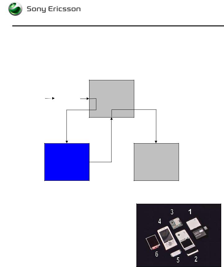
When you are going to replace a part being listed in Replacements, the instruction of that section usually begins by directing you to this Disassembly section with a specification of the instructions you have to carry out in order to disassemble the phone as far as needed before returning to Replacements for the actual replacement.
REPLACEMENTS
Start |
Contents |
|
page |
||
|
||
|
|
DISASSEMBLY |
REASSEMBLY |
 Done
Done
2.1 Overview
The disassembly is done in the following sequence:
1. M2, Battery Cover and Battery
2.Rear Back Cover
3.Main PCB
4.Front Cover Assembly
5.Navi Key PBA
6. Display
3/000 21-1/FEA 209 544/129 A |
6(34) |
Company Internal © Sony Ericsson Mobile Communications AB |
|
Working Instruction, Mechanical
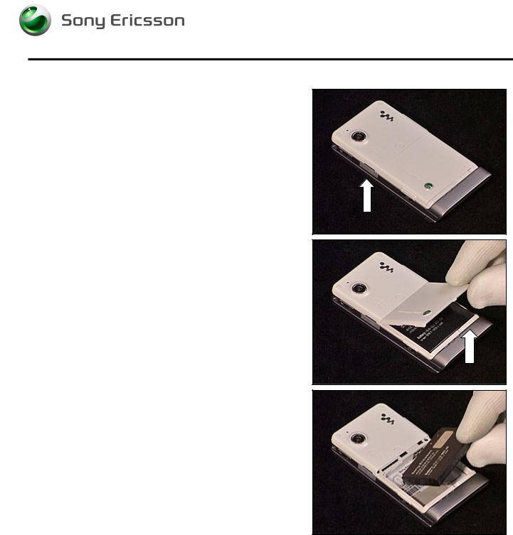
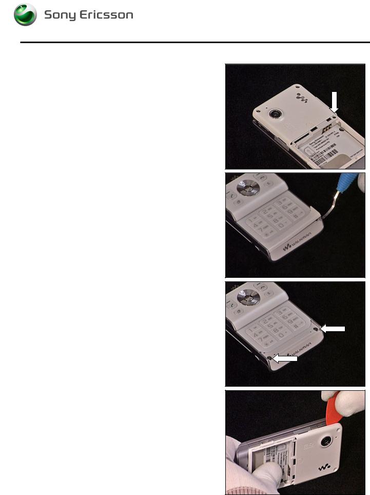
2.1.1 M2, Battery Cover and Battery
Open the MemoryStick Cap and remove the M2
MemoryStick.
Unlock the Battery Cover and remove it.
Remove the Battery.
3/000 21-1/FEA 209 544/129 A |
7(34) |
Company Internal © Sony Ericsson Mobile Communications AB |
|
Working Instruction, Mechanical
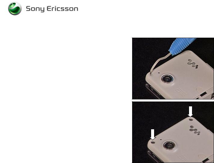
2.1.2 Rear Back Cover
Remove the screw Caps using a Dental hook.
Remove the two screws (Torx T6).
3/000 21-1/FEA 209 544/129 A |
8(34) |
Company Internal © Sony Ericsson Mobile Communications AB |
|
Working Instruction, Mechanical
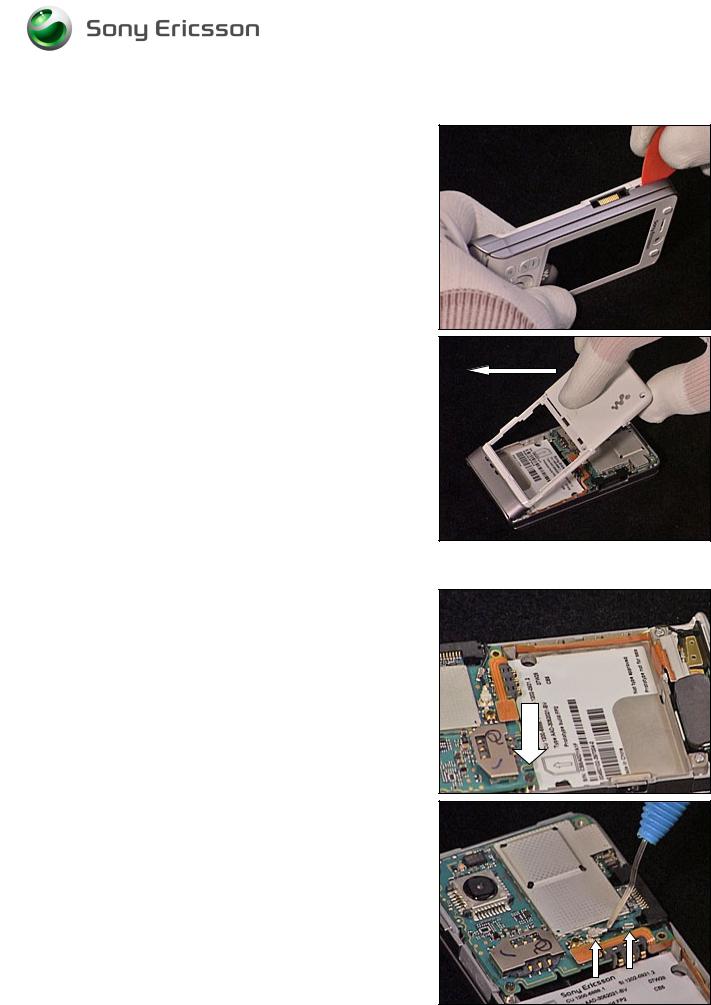
Rear back Cover continued
Remove the screw.
Remove the Panel Antenna using a Dental hook.
Remove the two screws (Torx T6).
Release the Rear Back Cover using a guitar pick, carefully sliding it along the side of the Cover Lower Rear.
3/000 21-1/FEA 209 544/129 A |
9(34) |
Company Internal © Sony Ericsson Mobile Communications AB |
|
Working Instruction, Mechanical
Rear Back Cover continued
Repeat the previous step on the other side of the phone.
Carefully remove the Rear Back Cover by lifting it 90 degrees from the unit as shown in picture.
2.1.3 Main PCB
Remove the screw.
Carefully release the Antenna Coax using a Dental hook.
3/000 21-1/FEA 209 544/129 A |
10(34) |
Company Internal © Sony Ericsson Mobile Communications AB |
|

Working Instruction, Mechanical
Main PCB continued
Carefully release the Speaker Flex Board to Board
Connector using an orange stick.
Carefully release the Main PCB from the frame using a guitar pick.
Carefully release the Front Flex Board to Board connector from the Main PCB using a guitar pick.
Remove the Main PCB.
2.1.4 Front Cover Assembly
Remove the two screw Caps using a Dental hook.
3/000 21-1/FEA 209 544/129 A |
11(34) |
Company Internal © Sony Ericsson Mobile Communications AB |
|
 Loading...