


3-868-361-25(1)
TFT LCD Color
Computer Display
Operating Instructions |
|
|
GB |
|||
|
|
|
|
|
|
|
Mode d’emploi |
|
|
|
|
|
FR |
|
|
|
|
|||
Bedienungsanleitung |
|
|
|
DE |
||
|
|
|
||||
Manual de instrucciones |
|
ES |
||||
|
|
|
||||
Istruzioni per l’uso |
|
|
|
|
IT |
|
SDM-N50
© 1999 Sony Corporation
Owner’s Record
The model and serial numbers are located at the rear of the unit. Record these numbers in the spaces provided below. Refer to them whenever you call upon your dealer regarding this product. Model No. Serial No.
WARNING
To prevent fire or shock hazard, do not expose the unit to rain or moisture.
Dangerously high voltages are present inside the unit. Do not open the cabinet. Refer servicing to qualified personnel only.
FCC Notice
This equipment has been tested and found to comply with the limits for a Class B digital device, pursuant to Part 15 of the FCC Rules. These limits are designed to provide reasonable protection against harmful interference in a residential installation. This equipment generates, uses, and can radiate radio frequency energy and, if not installed and used in accordance with the instructions, may cause harmful interference to radio communications. However, there is no guarantee that interference will not occur in a particular installation. If this equipment does cause harmful interference to radio or television reception, which can be determined by turning the equipment off and on, the user is encouraged to try to correct the interference by one or more of the following measures:
–Reorient or relocate the receiving antenna.
–Increase the separation between the equipment and receiver.
–Connect the equipment into an outlet on a circuit different from that to which the receiver is connected.
–Consult the dealer or an experienced radio/TV technician for help. You are cautioned that any changes or modifications not expressly approved in this manual could void your authority to operate this equipment.
INFORMATION
This product complies with Swedish National Council for Metrology (MPR) standards issued in December 1990 (MPR II) for very low frequency (VLF) and extremely low frequency (ELF).
INFORMATION
Ce produit est conforme aux normes du Swedish National Council for Metrology de décembre 1990 (MPR II) en ce qui concerne les fréquences très basses (VLF) et extrêmement basses (ELF).
INFORMACIÓN
Este producto cumple las normas del Consejo Nacional Sueco para Metrología (MPR) emitidas en diciembre de 1990 (MPR II) para frecuencias muy bajas (VLF) y frecuencias extremadamente bajas (ELF).
NOTICE
This notice is applicable for USA/Canada only.
If shipped to USA/Canada, install only a UL LISTED/CSA LABELLED power supply cord meeting the following
specifications: |
|
|
|
|||||
SPECIFICATIONS |
|
|
|
|||||
Plug Type |
Nema-Plug 5-15p |
|||||||
Cord |
Type SVT or SJT, minimum 3 × 18 AWG |
|||||||
Length |
Maximum 15 feet |
|||||||
Rating |
Minimum 7 A, 125 V |
|||||||
|
|
|
|
|
|
|
|
|
|
|
|
|
|
|
|
|
|
|
|
|
|
|
|
|
|
|
|
|
|
|
|
|
|
|
|
|
|
|
|
|
|
|
|
|
|
|
|
|
|
|
|
|
|
|
|
|
|
|
|
|
|
|
|
|
|
|
|
|
|
|
|
|
|
|
|
|
|
|
|
|
SONY SDM-N50
Sony Electronics Inc.
1 Sony Drive, Park Ridge, NJ 07656 USA
201-930-6972
This device complies with Part 15 of the FCC Rules. Operation is subject to the following two conditions: (1) This device may not cause harmful interference, and (2) this device must accept any interference received, including interference that may cause undesired operation.
2
Table of Contents
•Macintosh is a trademark licensed to Apple Computer, Inc., registered in the U.S.A. and other countries.
•Windows â and MS-DOS are registered trademarks of Microsoft Corporation in the United States and other countries.
•IBM PC/AT and VGA are registered trademarks of IBM Corporation of the U.S.A.
•VESA and DDC ä are trademarks of the Video Electronics Standard Association.
•ENERGY STAR is a U.S. registered mark.
•All other product names mentioned herein may be the trademarks or registered trademarks of their respective companies.
•Furthermore, “ ä” and “ â” are not mentioned in each case in this manual.
Precautions . . . . . . . . . . . . . . . . . . . . . . . . . . . . . . . . . . . . . . . . . . . 4 To enjoy clear sound from the built-in stereo speaker . . . . . . . . . . . 5 Identifying parts and controls . . . . . . . . . . . . . . . . . . . . . . . . . . . . . . 6
Setup . . . . . . . . . . . . . . . . . . . . . . . . . . . . . . . . . . . . . . . . .8
Step 1: Connect the media engine to your computer . . . . . . . . . . . 8 Step 2: Connect the display and media engine . . . . . . . . . . . . . . . . 8 Step 3: Connect the power cord . . . . . . . . . . . . . . . . . . . . . . . . . . . 9 Step 4: Turn on the monitor and computer . . . . . . . . . . . . . . . . . . . 9 Using the stereo speaker . . . . . . . . . . . . . . . . . . . . . . . . . . . . . . . . 10 Selecting the input signal . . . . . . . . . . . . . . . . . . . . . . . . . . . . . . . . 10
Customizing Your Monitor . . . . . . . . . . . . . . . . . . . . . . .11
Navigating the menu . . . . . . . . . . . . . . . . . . . . . . . . . . . . . . . . . . . 11 Adjusting the contrast (CONTRAST) . . . . . . . . . . . . . . . . . . . . . . . 12 Adjusting the black level of an image (BRIGHTNESS) . . . . . . . . . 12 Eliminating flicker or blurring (PHASE/PITCH) . . . . . . . . . . . . . . . 13 GB Adjusting the picture position (H CENTER/V CENTER) . . . . . . . . 13 Displaying a low-resolution signal at the actual resolution
(ZOOM). . . . . . . . . . . . . . . . . . . . . . . . . . . . . . . . . . . . . . . . . . . . . . 14 Adjusting the color temperature (COLOR) . . . . . . . . . . . . . . . . . . . 14 Changing the menu’s position (MENU POSITION) . . . . . . . . . . . . 14 Resetting the adjustments (RESET) . . . . . . . . . . . . . . . . . . . . . . . 15 Additional settings (Option) . . . . . . . . . . . . . . . . . . . . . . . . . . . . . . 15
Technical Features . . . . . . . . . . . . . . . . . . . . . . . . . . . . .17
Power saving function (user sensor/power saving mode) . . . . . . . 17 Automatic brightness adjustment function (light sensor) . . . . . . . . 18 Automatic picture quality adjustment function . . . . . . . . . . . . . . . . 18
Troubleshooting . . . . . . . . . . . . . . . . . . . . . . . . . . . . . . .19
On-screen messages . . . . . . . . . . . . . . . . . . . . . . . . . . . . . . . . . . . 19 Trouble symptoms and remedies . . . . . . . . . . . . . . . . . . . . . . . . . 20 Self-diagnosis function . . . . . . . . . . . . . . . . . . . . . . . . . . . . . . . . . . 22
Specifications . . . . . . . . . . . . . . . . . . . . . . . . . . . . . . . . .22
Appendix. . . . . . . . . . . . . . . . . . . . . . . . . . . . . . . . . . . . . . . i
Preset mode timing table . . . . . . . . . . . . . . . . . . . . . . . . . . . . . . . . . .i TCO’95 Eco-document . . . . . . . . . . . . . . . . . . . . . . . . . . . . . . . . . . . .i
3
Precautions
Warning on power connections
•Use the supplied power cord. If you use a different power cord, be sure that it is compatible with your local power supply.
For the customers in the U.S.A.
If you do not use the appropriate cord, this monitor will not conform to mandatory FCC standards.
For the customers in the UK
If you use the monitor in the UK, please use the appropriate UK power cord.
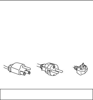
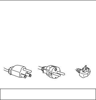
Example of plug types
for 100 to 120 V AC for 200 to 240 V AC for 240 V AC only
The equipment should be installed near an easily accessible outlet.
Installation
Do not install or leave the monitor:
•In places subject to extreme temperatures, for example near a radiator, heating vent, or in direct sunlight. Subjecting the monitor to extreme temperatures, such as in an automobile parked in direct sunlight or near a heating vent, could cause deformations of the casing or malfunctions.
•In places subject to mechanical vibration or shock.
•Near any equipment that generates a strong magnetic field, such as a TV or various other household appliances.
•In places subject to inordinate amounts of dust, dirt, or sand, for example near an open window or an outdoor exit. If setting up temporarily in an outdoor environment, be sure to take adequate precautions against airborne dust and dirt. Otherwise irreparable malfunctions could occur.
Handling the LCD screen
•Do not leave the LCD screen facing the sun as it can damage the LCD screen. Take care when you place the monitor by a window.
•Do not push on or scratch the LCD screen. Do not place a heavy object on the LCD screen. This may cause the screen to lose uniformity or cause LCD panel malfunctions.
•If the monitor is used in a cold place, a residual image may appear on the screen. This is not a malfunction. The screen returns to normal as the temperature rises to a normal operating level.
•If a still picture is displayed for a long time, a residual image may appear for a while. The residual image will eventually disappear.
•The LCD panel becomes warm during operation. This is not a malfunction.
About the bright points of light or black dots
Bright points of light (red, blue or green) or black dots may appear on the LCD screen. This is not a malfunction. The LCD screen is made with highprecision technology and more than 99.99 % of the picture element is intact. However, some of the picture element may not appear or some of the picture element may appear constantly.
Maintenance
•Be sure to unplug the power cord from the power outlet before cleaning your monitor.
•Clean the LCD screen with a soft cloth. If you use a glass cleaning liquid, do not use any type of cleaner containing an anti-static solution or similar additive as this may scratch the LCD screen’s coating.
•Clean the cabinet, panel, and controls with a soft cloth lightly moistened with a mild detergent solution. Do not use any type of abrasive pad, scouring powder, or solvent, such as alcohol or benzine.
•Do not rub, touch, or tap the surface of the screen with sharp or abrasive items such as a ballpoint pen or screwdriver. This type of contact may result in a scratched picture tube.
•Note that material deterioration or LCD screen coating degradation may occur if the monitor is exposed to volatile solvents such as insecticide, or if prolonged contact is maintained with rubber or vinyl materials.
Transportation
•Disconnect all cables from the monitor when transporting. When you transport this display, grasp the support and base sections of the display stand firmly with both hands. Also use both hands when carrying the media engine. If you drop the monitor, you may be injured or the monitor may be damaged.
•When you transport this monitor for repair or shipment, use the original carton and packing materials.
Replacement of the fluorescent tube
A specially designed fluorescent tube is installed as the lighting apparatus for this monitor. If the screen becomes dark, unstable, or does not turn on, replace the fluorescent tube with a new one. Consult your Sony dealer when replacing the fluorescent tube.
Disposal of the monitor
•Do not dispose of this monitor with general household waste.
•The fluorescent tube used in this monitor contains mercury. Disposal of this monitor must be carried out in accordance to the regulations of your local sanitation authority.
4
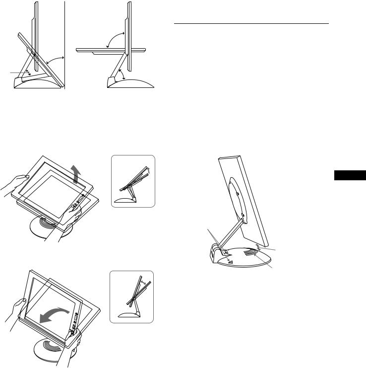
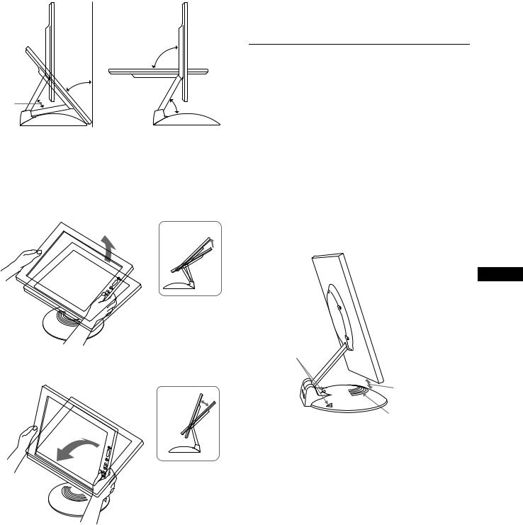
To adjust the tilt and height
This display can be adjusted within the angles shown below.
90°
40°
50° |
50° |
To adjust the angles, grasp the lower sides of the LCD panel with both hands as shown below. Tilt the LCD panel adequately backward, then lift the LCD panel upward to the desired screen height, then adjust the screen tilt as desired. When adjusting the screen height and tilt, proceed slowly and carefully, being sure not to hit the LCD panel against the desk or the base of the display stand.
To use the display comfortably
This display is designed so that you can set it up at a comfortable viewing angle. Adjust the viewing angle of your display according to the height of the desk and chair, and so that light is not reflected from the screen to your eyes.
To enjoy clear sound from the builtin stereo speaker
This monitor has a built-in stereo speaker in base of the display stand.
We recommend that you position the LCD panel slightly away from the display stand. High tones from the speaker may be muffled if the LCD panel is positioned immediately on top of the stand. Be careful not to drop any metal object into the speaker's vents as the speakers generate a magnetic field. Also, this magnetic field may affect data stored on magnetic tapes and discs. Be sure to keep magnetic recording equipment, tapes, and floppy discs away from the speaker’s opening.
A duct is provided on the rear part of the display stand to boost the bass. Be sure not to block the duct with paper or other objects to ensure clear sound.
GB
m
Ducts
Keep the LCD panel slightly away from the base.
Speaker
5
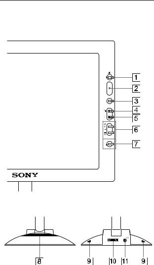
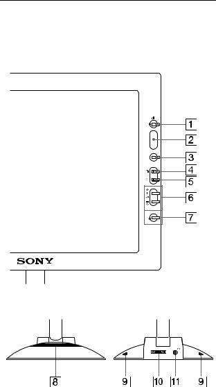
Identifying parts and controls
See the pages in parentheses for further details.
LCD display
MENU
INPUT
1
2
OK
Front |
Rear |
SYSTEM CONNECTER
6 2 (volume) +/– and M(+)/m(–) buttons
(pages 10, 12)
These buttons display the VOLUME menu and function as the M(+)/m(–) buttons when selecting the menu items and making adjustments.
7INPUT and OK button, and indicator (pages 10, 12)
This button selects the INPUT 1 or INPUT 2 (HD15 (RGB) connectors) video input signal. The input signal and corresponding input indicator change each time you press this button.
This button also functions as the OK button when displaying the menu on the screen.
8Stereo speaker (page 10)
This outputs the audio signals as sound.
9Ducts
These are used to boost the bass sound from the speaker.
0SYSTEM CONNECTOR (page 8)
This connector inputs signals from the media engine when the display and the media engine are connected with a system connecting cable.
qa Headphones jack (page 10)
This jack outputs audio signals to the headphones.
11 (Power) switch and indicator (pages 9, 17, 22)
This switch turns the display on and off.
The indicator lights up in green when the monitor is turned on. The indicator flashes in green and orange when the monitor is in low power consumption mode, and lights up in orange when the monitor is in power saving mode.
2Light sensor and user sensor (pages 16, 17, 18)
These sensors measure the brightness of the surrounding area and detect when a user becomes present in front of the screen. Be sure not to cover the sensor with papers, etc.
3MENU button (page 12)
This button displays the main menu.
4 6 (contrast) button (page 12)
This button displays the CONTRAST menu.
5 8 (brightness) button (page 12)
This button displays the BRITGHTNESS menu.
6
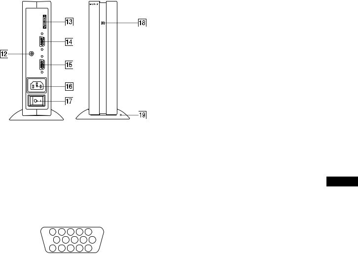
Media engine
SYSTEM CONNECTER (TO DISPLAY)
INPUT 1
AUDIO IN
INPUT 2
qs AUDIO IN jack (page 10)
This jack inputs audio signals when connecting to the audio output jack of the computer or other audio equipment.
qd SYSTEM CONNECTOR (TO DISPLAY) (page 8)
This connector outputs signals to the display when the display and the media engine are connected with a system connecting cable.
qf HD15 (RGB) input 1 connector (INPUT1) (page 8)
This connector inputs RGB video signals (0.700 Vp-p, positive) and SYNC signals.
|
5 |
|
4 |
3 |
2 |
1 |
|
10 |
9 |
8 |
7 |
6 |
|
|
15 |
14 |
13 12 |
11 |
||
|
|
|
|
|
|
|
Pin No. |
Signal |
|
|
|
|
|
|
|
|
|
|
|
|
1 |
Red |
|
|
|
|
|
|
|
|
|
|
|
|
2 |
Green |
|
|
|
|
|
|
(Sync on Green) |
|
|
|||
|
|
|
|
|
|
|
3 |
Blue |
|
|
|
|
|
|
|
|
|
|
||
4 |
ID (Ground) |
|
|
|
||
|
|
|
|
|
||
5 |
DDC Ground* |
|
|
|
||
|
|
|
|
|
||
6 |
Red Ground |
|
|
|
||
|
|
|
|
|
||
7 |
Green Ground |
|
|
|
||
|
|
|
|
|
||
8 |
Blue Ground |
|
|
|
||
|
|
|
|
|
|
|
9 |
DDC + 5V* |
|
|
|
|
|
|
|
|
|
|
|
|
10 |
Ground |
|
|
|
|
|
|
|
|
|
|
||
11 |
ID (Ground) |
|
|
|
||
|
|
|||||
12 |
Bi-Directional Data (SDA)* |
|||||
|
|
|
|
|
|
|
13 |
H. Sync |
|
|
|
|
|
|
|
|
|
|
|
|
14 |
V. Sync |
|
|
|
|
|
|
|
|
|
|||
15 |
Data Clock (SCL)* |
|
|
|||
|
|
|
|
|
|
|
* DDC (Display Data Channel) is a standard of VESA.
qg HD15 (RGB) input 2 connector (INPUT2) (page 8)
This connector inputs RGB video signals (0.700 Vp-p, positive) and SYNC signals. The pin assignment is the same as qf.
qh AC IN connector (page 9)
This connector provides AC power to the monitor.
qj AC power switch (page 9)
This switch turns the monitor on and off. When the AC power switch is turned on, the display automatically turns on.
qk AC power indicator (page 17)
This indicator lights up in green when the media engine is turned on. The indicator lights up in red when the display is turned off with the media engine on. The indicator lights up in orange when the monitor is in the power saving mode.
ql Media engine stand
This stand is used to install the media engine vertically.
Caution
Be sure to install the media engine vertically shown as left. Installing the media engine lying flat may block ventilation, and may cause a malfunction.
GB
7
Setup
Before using your monitor, check that the following accessories are included in your carton:
•LCD display
•Media engine
•Media engine stand
•Power cord
•System connecting cable (2 m) (applicable cable type: DP-2)
•HD15 (RGB) video signal cable
•Audio cord (stereo miniplug)
•Macintosh adapter
•Windows Monitor Information Disk/Utility Disk
•Macintosh Utility Disk
•Warranty card
•Notes for Macintosh users
•This instruction manual
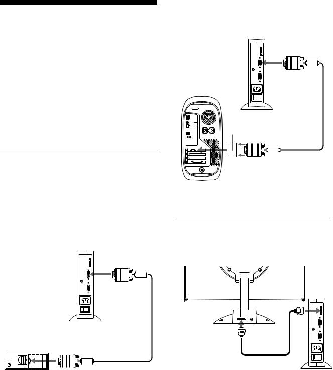
Step 1: Connect the media engine to your computer
Turn off the media engine and computer before connecting.
Note
Do not touch the pins of the video signal cable connector as this might bend the pins.
xConnecting to an IBM PC/AT or compatible computer
to INPUT1 or INPUT2 connector
|
to video output |
|
HD15 (RGB) video |
IBM PC/AT or |
signal cable (supplied) |
compatible computer |
|
xConnecting to a Macintosh or compatible computer
Use the supplied Macintosh adapter.
to INPUT1 or INPUT2 connector
Macintosh adapter (supplied)*
to video output |
HD15 (RGB) video |
|
signal cable (supplied) |
||
|
Macintosh or compatible computer
* Refer to the supplied “Notes for Macintosh users” for further details.
Step 2: Connect the display and media engine
Turn off the display and media engine before connecting.
to SYSTEM |
to SYSTEM |
CONNECTOR |
CONNECTOR |
of the display |
of the media |
|
engine |
|
system connecting |
|
cable (2 m) (supplied) |
Caution
Be sure to install the media engine vertically shown as above. Installing the media engine lying flat may block ventilation, and may cause a malfunction.
Note
Grasp the plug when connecting the cable.
8
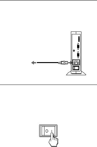
Step 3: Connect the power cord
With the media engine, display, and computer switched off, first connect the power cord to the media engine, then connect it to a power outlet.
to AC IN
to a power outlet
power cord (supplied)
Step 4: Turn on the monitor and computer
1Turn on the media engine.
The display automatically turns on. The indicators of the media engine and display light up in green.
2 Turn on the computer.
The installation of your monitor is complete. If necessary, use the monitor’s controls to adjust the picture.
If no picture appears on your screen
•Check that the monitor is correctly connected to the computer.
•Check that the media engine is on.
•If NO INPUT SIGNAL appears on the screen, the computer is in the power saving mode. Try pressing any key on the keyboard or moving the mouse.
•If CABLE DISCONNECTED appears on the screen, try changing the input signal (page 10), and check that the video input cable is properly connected.
•If OUT OF SCAN RANGE appears on the screen, reconnect the old monitor. Then adjust the computer’s graphic board so that the horizontal frequency is between 30 – 61 kHz, and the vertical frequency is between 48 – 85 Hz (only XGA mode at 75 Hz).
For more information about the on-screen messages, see “Trouble symptoms and remedies” on page 20.
For customers using Windows 95/98 |
|
|
To maximize the potential of your monitor, install the new model |
|
|
information file from the supplied Windows Monitor Information Disk |
|
|
onto your PC. |
|
|
This monitor complies with the “VESA DDC” Plug & Play standard. If |
|
|
your PC/graphics board complies with DDC, select “Plug & Play Monitor |
|
|
(VESA DDC)” or this monitor’s model name as the monitor type in the |
|
|
“Control Panel” of Windows 95/98. If your PC/graphics board has |
|
|
difficulty communicating with this monitor, load the Windows Monitor |
|
|
Information Disk and select this monitor’s model name as the monitor |
|
|
GB |
||
type. |
||
|
||
For customers using Windows NT4.0 |
|
|
Monitor setup in Windows NT4.0 is different from Windows 95/98 and |
|
|
does not involve the selection of monitor type. Refer to the Windows |
|
|
NT4.0 instruction manual for further details on adjusting the resolution, |
|
|
refresh rate, and number of colors. |
|
|
Adjusting the monitor’s resolution and color number |
|
|
Adjust the monitor’s resolution and color number by referring to your |
|
|
computer’s instruction manual. The color number may vary according to |
|
|
your computer or video board. The color palette setting and the actual |
|
|
number of colors are as follows: |
|
|
• High Color (16 bit) t 65,536 colors |
|
|
• True Color (24 bit) t about 16.77 million colors |
|
|
In true color mode (24 bit), speed may be slower. |
|
9
Using the stereo speaker
You can listen to music, sounds, and other audio files using the stereo speaker of your monitor.
Connect the AUDIO IN jack to the audio output jack of your computer or other audio equipment using the supplied audio cord (stereo miniplug).
Adjusting the volume
Volume adjustments are made using a separate VOLUME menu from the main menu (page 11).
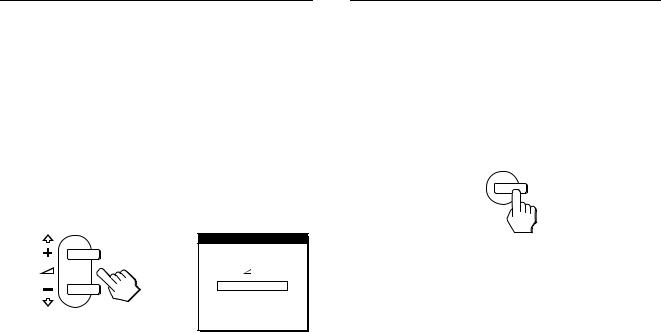
1Press the 2 +/– buttons.
The VOLUME menu appears on the screen.
VOL UME
4 0
2 Press the 2 +/– button to adjust the volume.
The menu automatically disappears after about 3 seconds.
Using the headphones jack
You can listen to the audio signals from your computer or other audio equipment using headphones. Connect your headphones to the headphones jack. The speaker turns off when headphones are connected to the headphones jack. Adjust the volume of the headphones using the VOLUME menu.
Notes
•You cannot adjust the volume when displaying the main menu on the screen.
•When your monitor is in low power consumption mode or power saving mode, no sound comes from the speaker.
Selecting the input signal
You can connect two computers to this monitor using the INPUT 1 and INPUT 2 connectors. To select one of the two computers, use the INPUT button.
Press the INPUT button.
The input signal and corresponding input indicator, “1” (INPUT 1) or “2” (INPUT 2) change each time you press this button.
INPUT
1
2
OK
Notes
•You cannot select the input signal when displaying the main menu on the screen.
•If no signal is input to the selected connector, NO INPUT SIGNAL or CABLE DISCONNECTED appears on the screen. After a few seconds, the monitor enters the power saving mode. If this happens, select the other connector using the INPUT button.
10

Customizing Your Monitor
Before making adjustments
Connect the monitor and the computer, and turn them on. Wait for at least 30 minutes before making adjustments for the best result.
You can make numerous adjustments to your monitor using the on-screen menu.
Navigating the menu
Press the MENU button to display the main menu on your screen. See page 12 for more information on using the MENU button.
PHA SE
MENU
Use the M(+)/m(–) and OK buttons to select one of the following menus. See page 12 for more information on using the M(+)/m(–) and OK buttons.
1 PHASE (page 13)
Select the PHASE menu to adjust the phase when the characters or pictures appear fuzzy throughout the entire screen. Adjust the phase after adjusting the pitch.
2PITCH (page 13)
Select the PITCH menu to adjust the pitch when the characters or pictures are unclear in some areas of the screen.
3H CENTER (page 13)
Select the H CENTER menu to adjust the picture’s horizontal centering.
1 6 |
EX I T |
P I T C H |
0 |
EX I T |
H CENT ER |
5 0 |
EX I T |
4V CENTER (page 13)
Select the V CENTER menu to adjust the picture’s vertical centering.
5ZOOM (page 14)
Select the ZOOM menu to adjust the picture’s sharpness according to the input signal’s aspect ratio or resolution.
6COLOR (page 14)
Select the COLOR menu to adjust the color temperature of the picture. This adjusts the tone of the screen.
7MENU POSITION (page 14)
Select the MENU POSITION to change the onscreen menu position.
8RESET (page 15)
Select the RESET menu to reset the adjustments.
9Option (page 15)
Select m (option) menu to
adjust the monitor’s options. The options include:
•WIDE STEREO
•BASS BOOST
•BACKLIGHT
•LIGHT SENSOR
•POWER SAVE
•USER SENSOR
•LANGUAGE
•MENU LOCK
V CENT ER |
2 5 |
EX I T |
ZOOM |
 ON
ON
OFF
EX I T |
|
COLOR |
|
9 3 0 0 K |
|
6 5 0 0 K |
|
5 0 0 0 K |
|
USER |
|
L AD J U ST |
|
EX I T |
|
MENU POS I T I ON |
GB |
|
|
EX I T |
RESE T |
|
S CREEN RESE T |
|
A L L |
RESE T |
|
EX I T |
W I D E S T E R EO |
|
1 |
|
2 |
|
OF F |
|
EX I T
(continued)
11
x Using the MENU, M(+)/m(–), and OK buttons
1Display the main menu.
Press the MENU button to display the main menu on your screen.
MENU
2Select the menu you want to adjust.
Press the M(+)/m(–) buttons to display the desired menu. Press the OK button to select the menu item.
INPUT
, 12
OK
3Adjust the menu.
Press the M(+)/m(–) buttons to make the adjustment. Then press the OK button to return to the previous menu.
INPUT
, 12
OK
4Close the menu.
Press the MENU button once to return to normal viewing. If no buttons are pressed, the menu closes automatically after about 30 seconds.
MENU
x Resetting the adjustments
You can reset the adjustments using the RESET menu. See page 15 for more information on resetting the adjustments.
Adjusting the contrast (CONTRAST)
Contrast adjustment is made using a separate CONTRAST menu from the main menu (page 11). This setting is stored in memory for the signal from the currently selected input connector.
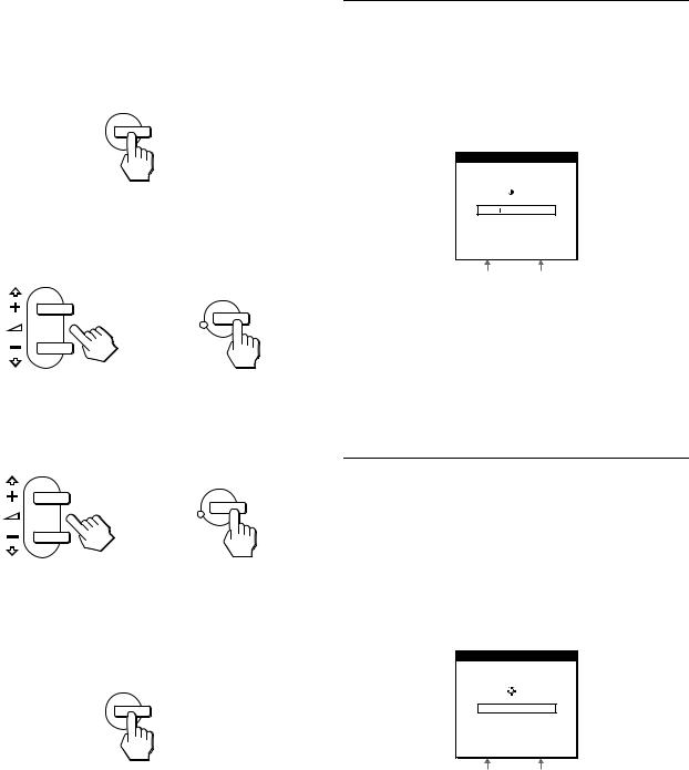
1Press the 6 (contrast) button.
The CONTRAST menu appears on the screen.
CONTRAS T
7 0
4 8 . 4 k H z / 6 0 H z
Horizontal frequency |
Vertical frequency of |
of the current input |
the current input |
signal |
signal |
Displaying the current input signal
The horizontal and vertical frequencies of the current input signal are displayed in the CONTRAST and BRIGHTNESS menu.
2 Press the M(+)/m(–) buttons to adjust the contrast.
The menu automatically disappears after about 3 seconds.
Adjusting the black level of an image (BRIGHTNESS)
Brightness adjustment is made using a separate BRIGHTNESS menu from the main menu (page 11). This setting is stored in memory for the signal from the currently selected input connector.
1Press the 8 (brightness) button.
The BRIGHTNESS menu appears on the screen.
BR I GHTNESS
5 0
4 8 . 4 k H z / 6 0 H z
Horizontal frequency |
Vertical frequency of |
of the current input |
the current input |
signal |
signal |
2Press the M(+)/m(–) buttons to adjust the brightness.
The menu automatically disappears after about 3 seconds.
If the screen is too bright
Adjust the backlight. For more information about adjusting the backlight see “Adjusting the backlight” on page 16.
Note
You can adjust neither contrast nor brightness when displaying the main menu on the screen.
12
Eliminating flicker or blurring (PHASE/PITCH)
When the monitor receives an input signal, the automatic picture quality adjustment function of this monitor automatically adjusts the picture position, phase, and pitch, and ensures that a clear picture appears on the screen. For more information about this function, see “Automatic picture quality adjustment function” on page 18.
For some input signals, this function may not completely adjust the picture position, phase, and pitch. In this case, you can manually set these adjustments according the following instructions. If you manually set these adjustments, they are stored in memory and automatically recalled whenever the monitor receives the same input signals.
These settings may have to be repeated if you change the input signal after reconnecting your computer.
1Set the resolution to 1024 × 768 on the computer.
2Load the Utility Disk.
Use the appropriate disk for your computer.
For Windows 95/98
Windows Monitor Information Disk/Utility Disk
For Macintosh
Macintosh Utility Disk
3Start the Utility Disk and display the test pattern. For Windows 95/98
Click [Utility Disk] t [Windows]/[Utility.exe].
For Macintosh
Click [Utility Disk] t [SONY-Utility].
4Press the MENU button.
The main menu appears on the screen.
5 Press the M(+)/m(–) buttons to select |
|
|
|
|
|
|
|
(PITCH) |
|
|
|
|
and press the OK button.
The PITCH menu appears on the screen.
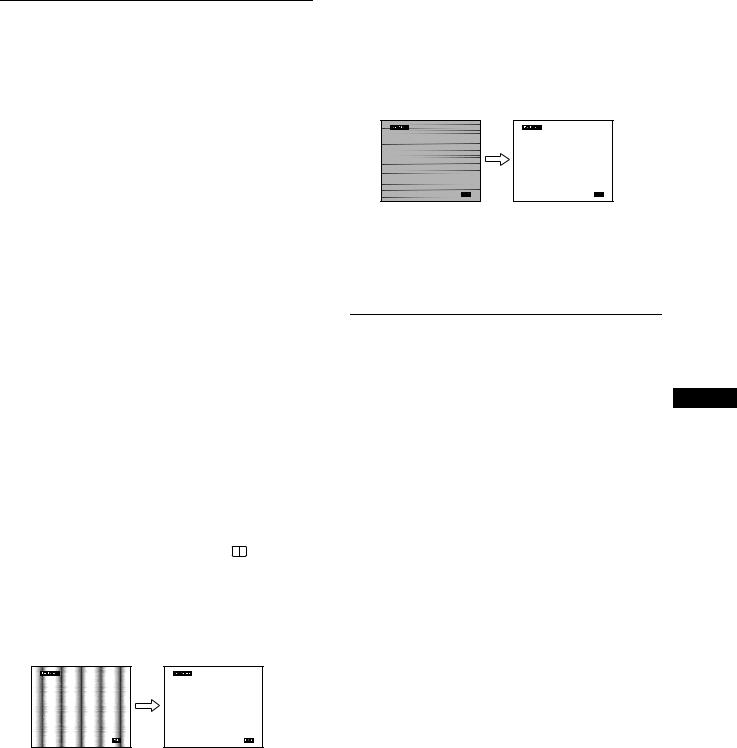
6Press the M(+)/m(–) buttons until the screen color becomes uniform.
Adjust so that the vertical stripes disappear.
7Press the OK button.
The main menu appears on the screen.
If horizontal stripes are observed over the entire screen, adjust the phase as the next step.
8Press the M(+)/m(–) buttons to select  (PHASE) and press the OK button.
The PHASE menu appears on the screen.
9Press the M(+)/m(–) buttons until the screen color becomes uniform.
Adjust so that the horizontal stripes are at a minimum.
10 Click [END] on the screen to turn off the test pattern.
To reset the automatic picture quality adjustment
Select SCREEN RESET and activate it using the RESET menu. See page 15 for more information on using the RESET menu.
Adjusting the picture position (H CENTER/V CENTER)
If the picture is not in the center of the screen, adjust the picture’s centering as follows. GB These settings may have to be repeated if you change the input
signal after reconnecting your computer.
1Start the Utility Disk and display the test pattern.
Repeat steps 2 and 3 of “Eliminating flicker or blurring (PHASE/PITCH).”
2Press the MENU button.
The main menu appears on the screen.
3Press the M(+)/m(–) buttons to select 
 (H
(H
CENTER) or  (V CENTER) and press the OK button.
The H CENTER or V CENTER menu appears on the screen.
4Move the picture up, down, left, or right until the frame at the perimeter of the test pattern
disappears.
Press the M(+)/m(–) buttons to adjust the picture’s centering using the H CENTER menu for horizontal adjustment, or the V CENTER menu for vertical adjustment.
5Click [END] on the screen to turn off the test pattern.
13
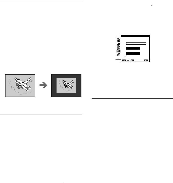
Displaying a low-resolution signal at the actual resolution (ZOOM)
This monitor is preset at the factory to display pictures on the screen in full, irrespective of the picture’s mode or resolution. You can also view the picture at its actual resolution.
1Press the MENU button.
The main menu appears on the screen.
2Press the M(+)/m(–) buttons to select 
 (ZOOM) and press the OK button.
The ZOOM menu appears on the screen.
3Press the m(–) button to select OFF.
The input signal is displayed on the screen at its actual resolution.
4 If necessary, fine tune the color temperature.
First press the M(+)/m(–) buttons to select ADJUST and press the OK button. Then press the M(+)/m(–) buttons to select R (Red) or B (Blue) and press the OK button, and then press the M(+)/m(–) buttons to adjust the color temperature. Since this adjustment changes the color temperature by increasing or decreasing the R and B components with respect to G (green), the G component is fixed.
USE R AD J USTMENT |
|
R |
1 6 8 |
G |
1 7 0 |
B |
1 7 5 |
|
EX I T |
If you fine tune the color temperature, the new color setting is stored in memory for USER ADJUSTMENT and automatically recalled whenever USER is selected.
The USER ADJUSTMENT setting is common to both the input signals. If you change the user adjustment setting for one input signal, the setting for the other input signal is also changed.
To display the picture on the screen in full
Select ON in step 3.
Adjusting the color temperature (COLOR)
The COLOR settings allow you to adjust the picture’s color temperature by changing the color level of the white color field. Colors appear reddish if the temperature is low, and bluish if the temperature is high.
9300K is generally suitable for word processing and other text oriented applications, and 6500K is generally suitable for video images.
You can set the color temperature to 5000K, 6500K, 9300K or user adjustment.
1Press the MENU button.
The main menu appears on the screen.
2Press the M(+)/m(–) buttons to select  (COLOR) and press the OK button.
The COLOR menu appears on the screen.
3Press the M(+)/m(–) buttons to select the desired color temperature.
The preset color temperatures are 5000K, 6500K, and 9300K. Since the default setting is 9300K, the whites will change from a bluish hue to a reddish hue as the temperature is lowered to 6500K and 5000K.
You can set separate color temperatures for each of the video input signals.
Changing the menu’s position (MENU POSITION)
You can change the menu position if it is blocking an image on the screen.
1Press the MENU button.
The main menu appears on the screen.
2Press the M(+)/m(–) buttons to select  (MENU
(MENU
POSITION) and press the OK button.
The MENU POSITION menu appears on the screen.
3Press the M(+)/m(–) buttons to select the desired position.
There are three positions each for the top of the screen and the bottom of the screen, and one for the screen center.
14

Resetting the adjustments (RESET)
This monitor has the following two reset methods. Use the RESET menu to reset the adjustments.
1Press the MENU button.
The main menu appears on the screen.
2Press the M(+)/m(–) buttons to select 0 (RESET) and press the OK button.
The RESET menu appears on the screen.
Reset the settings according to the following instructions.
Resetting the adjustment data most appropriately for the current input signal
Press the M(+)/m(–) buttons to select SCREEN RESET and press the OK button.
The automatic picture quality adjustment function of this monitor automatically adjusts the picture position, phase, and pitch, to the most appropriate value. If this function is activated, the phase is automatically adjusted whenever the monitor receives the same input signal.
The RESET menu is automatically returned to the main menu after the adjustment data is reset.
Resetting all of the adjustment data for all input signals
Press the M(+)/m(–) buttons to select ALL RESET and press the OK button.
The RESET menu is automatically returned to the main menu after the adjustment data is reset.
To cancel resetting
Press the M(+)/m(–) buttons to select  and press the
OK button.
The RESET menu returns to the main menu without resetting the adjustment data.
Additional settings (Option)
You can adjust the following options:
•WIDE STEREO
•BASS BOOST
•BACKLIGHT
•LIGHT SENSOR
•POWER SAVE
•USER SENSOR
•LANGUAGE
•MENU LOCK
1Press the MENU button.
The main menu appears on the screen.
2Press the M(+)/m(–) buttons to select m.
The option menu appears on the screen.
3Press the M(+)/m(–) buttons to select the desired option item and press the OK button.
Adjust the selected option item according to the following instructions.
Increasing the soundscape (wide stereo function)
This adjustment makes use of the DSP and creates the illusion of |
|
the built-in stereo speaker being further away than it actually is, |
GB |
thus enhancing sound presence. |
First press the M(+)/m(–) buttons to select 
 (WIDE
(WIDE
STEREO) and press the OK button. Then press the M(+)/m(–) buttons to select either 2, 1, or OFF.
The wide stereo function is used to increase the soundscape. Selecting 1 or 2 increases incrementally the soundscape effect toward the front of the monitor.
Notes
•If your connected computer or audio equipment uses special sound functions, such as surround sound, be sure to turn these functions off. If these functions are being used with the wide stereo function of this monitor, the wide stereo function may not function properly and thus not produce the desired sound effect.
•This function is automatically turned off when you use headphones. However, in this case, the indication in the WIDE STEREO menu does not change.
•The wide stereo function allows you to increase the soundscape by converting the analog signals into digital. The sound may be distorted depending on the input signal and music. In this case, decrease the volume or set the wide stereo function to OFF.
Boosting the bass (bass boost function)
This option increases the bass output of the speaker.
First press the M(+)/m(–) buttons to select  (BASS
(BASS
BOOST) and press the OK button. Then press the M(+)/m(–) buttons to select either ON or OFF.
(continued)
15

Adjusting the backlight
If the screen is too bright, adjust the backlight.
First press the M(+)/m(–) buttons to select


 (BACKLIGHT) and press the OK button. Then press the M(+)/m(–) buttons to adjust the desired light level.
Automatically adjusting the screen brightness (light sensor)
This monitor is provided with a sensor to detect the brightness of the surrounding area (light sensor). This sensor is used to automatically adjust the brightness of the screen.
First press the M(+)/m(–) buttons to select  (LIGHT
SENSOR) and press the OK button. Then press the M(+)/m(–) buttons to select either ON or OFF.
When you select ON, the monitor automatically adjusts the screen brightness according to the brightness of the surroundings. For more information about this function, see “Automatic brightness adjustment function (light sensor)” on page 18.
Note
If this function is set to ON, the value of the BACKLIGHT menu does not change. If the screen brightness is still not appropriate after the automatic adjustment, you can manually adjust the backlight. After the backlight adjustment is made, the monitor automatically adjusts the screen brightness in accordance with the new backlight value.
Setting up the power saving mode
This monitor has a function which enables it to enter the power save mode automatically according to the power saving settings of the computer. You can prevent the monitor from entering the power saving mode by setting the following option to OFF.
First press the M(+)/m(–) buttons to select  ZZ... (POWER
SAVE) and press the OK button. Then press the M(+)/m(–) buttons to select either ON or OFF.
Using the user sensor
The user sensor function enables the monitor to enter the low power consumption mode when no one is present in front of the monitor.
First press the M(+)/m(–) buttons to select  (USER
(USER
SENSOR) and press the OK button. Then press the M(+)/m(–) buttons to select either ON or OFF.
If you select ON, the monitor automatically enters the low power consumption mode when you move away from the front of the monitor. For more information about the low power consumption mode, see “Power saving function (user sensor/power saving mode)” on page 17.
Selecting the on-screen menu language
English, German, French, Spanish, Italian and Japanese versions of the on-screen menus are available. The default setting is English.
First press the M(+)/m(–) buttons to select

 (LANGUAGE) and press the OK button. Then press the M(+)/m(–) button to select a language.
•ENGLISH
•DEUTSCH: German
•FRANÇAIS: French
•ESPAÑOL: Spanish
•ITALIANO: Italian
•
 : Japanese
Locking the menus and controls
You can protect adjustment data by locking the menus and controls.
First press the M(+)/m(–) buttons to select  (MENU
(MENU
LOCK) and press the OK button. Then press the M(+)/m(–) buttons and select ON.
Only the 1 (power) switch, and  (MENU LOCK) of the option menu will operate. If any other items are selected, the
  mark appears on the screen.
To cancel the menu lock
Repeat the procedure above and set and  (MENU LOCK) to OFF.
16

Technical Features
Power saving function (user sensor/power saving mode)
This monitor meets the power-saving guidelines set by VESA, ENERGY STAR, and NUTEK. If the monitor is connected to a computer or video graphics board that is DPMS (Display Power Management Signaling) compliant, the monitor will automatically enter the power saving mode. It automatically enters the low power consumption mode when the user sensor detects the absence of a user.
Power consumption state |
Power consumption |
AC power indicator |
1 (power) indicator |
|
|
|
|
normal operation |
35 W |
green |
green |
|
|
|
|
1 low power consumption mode |
≤ 8 W |
green |
green and orange alternate |
|
|
|
|
2 power saving mode |
≤ 3 W |
orange |
orange |
|
|
|
|
1 (power): off |
≤ 3 W |
red |
off |
|
|
|
|
AC power: off |
0 W |
off |
off |
|
|
|
|
1 Low power consumption mode (user sensor)
When the user sensor in the monitor detects the absence of a user, the monitor enters low power consumption mode after about 20 seconds. In low power consumption mode, the monitor is in a power saving state and shuts off power to all circuitry (except for that of the sensors) regardless of the setting of the computer. The monitor returns to normal operation mode when the presence of a user is detected by the user sensor.
When the monitor enters the power saving mode (as set according to the computer’s settings), the power saving mode takes precedence over the low power consumption mode. In this case, the monitor stays in the power saving mode regardless of the presence or absence of a user.
To return the monitor to normal operation mode, reset the computer’s power saving mode.
Note
The user sensor detects the presence/absence of a user up to a distance of approximately 60 cm from the screen surface. However, this distance may vary depending on the user’s clothes or the brightness of the surrounding area. If user detection fails due to the ambient conditions of the surrounding area, set the user sensor to OFF. If your monitor does not automatically return from low power consumption mode due to the failure of the user sensor to detect the presence of a user, press the 1 (power) switch twice to turn the monitor off and then on.
2 Power saving mode
DPMS defines three power saving states according to the state of the sync signals supplied from the computer. This monitor’s power consumption is input at approximately 3 W in all of these states if the power saving function is set to ON.
When your computer enters in the power saving mode, the input GB signal is cut and NO INPUT SIGNAL appears on the screen.
After a few seconds, the monitor enters power saving mode.
Power saving |
Sync signal state |
state |
|
|
|
suspend (sleep)* |
horizontal: on / vertical: off |
|
|
standby (sleep)* |
horizontal: off / vertical: on |
|
|
active off (deep sleep)* |
horizontal: off / vertical: off |
|
|
*“Sleep” and “deep sleep” are power saving modes defined by the Environmental Protection Agency.
Note
The power saving function may not work normally if sync signals other than those listed above are supplied. In such a case, set the power saving function to OFF.
17
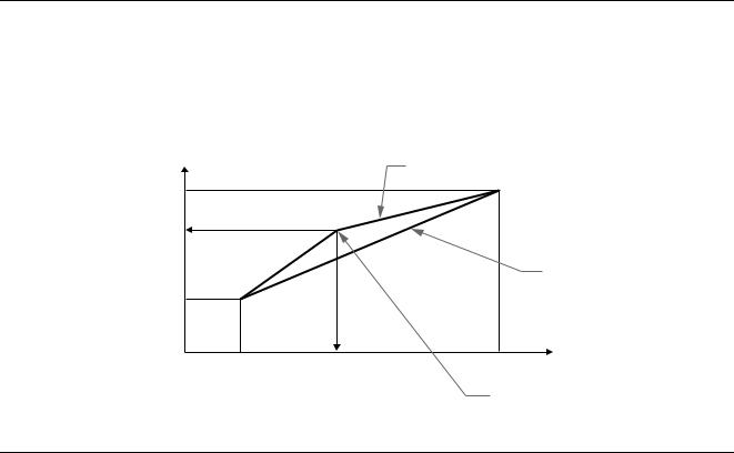
Automatic brightness adjustment function (light sensor)
This monitor is provided with a feature to automatically adjust the screen brightness according to the brightness of the surroundings. The brightness of the backlight is set to the most appropriate level by setting the light sensor to ON. The default setting of the brightness of the backlight is set to its maximum. When the light sensor setting is set to ON, the monitor adjusts the brightness of the backlight linearly from its lowerto upper-limit values. When the user adjusts the backlight, the backlight brightness is automatically adjusted between the user adjustment value and the upperand lower-limit values.
Backlight brightness
Automatic brightness adjustment |
after user adjustment |
Maximum |
User adjustment value |
Preset automatic adjustment |
Minimum |
Brightness during |
Brightness of surroundings |
user adjustment |
|
User-specified brightness value
Automatic picture quality adjustment function
When the monitor receives an input signal, it automatically matches the signal to one of the factory preset modes stored in the monitor’s memory to provide a high quality picture at the center of the screen. (See Appendix for a list of the factory preset modes.)
For input signals that do not match one of the factory preset modes, the automatic picture quality adjustment function of this monitor automatically adjusts the picture position, phase, and pitch, and ensures that a clear picture appears on the screen for any timing within the monitor’s frequency range (horizontal: 30 – 61 kHz, vertical: 48 – 85 Hz).
Consequently, the first time the monitor receives input signals that do not match one of the factory preset modes, the monitor may take a longer time than normal for displaying the picture on the screen. This adjustment data is automatically stored in memory so that next time, the monitor will function in the same way as when the monitor receives the signals that match one of the factory preset modes.
In all modes as above, if the picture is adjusted, the adjustment data is stored as a user mode and automatically recalled whenever the same input signal is received.
Note on the adjusting the phase
If the automatic picture quality adjustment function is activated, the picture moves slightly whenever the monitor receives the input signal, regardless of the stored adjustment.
Note
While the automatic picture quality adjustment function is activated, only the 1 (power) switch, and INPUT button will operate.
18
If CABLE DISCONNECTED appears on the screen
Troubleshooting |
This indicates that the video signal cable has been disconnected |
||
|
|||
|
from the currently selected connector. |
||
Before contacting technical support, refer to this section. |
|
|
|
|
|
|
|
|
|
|
|
|
|
|
|
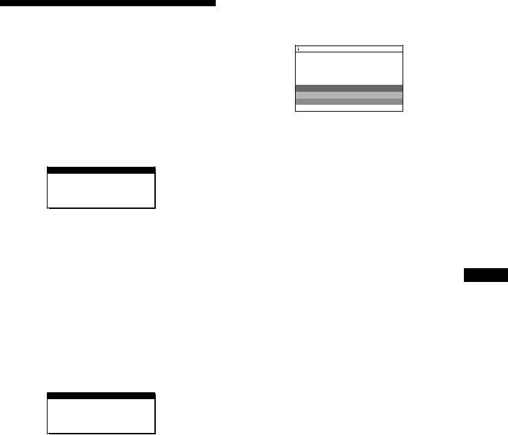
On-screen messages
If there is something wrong with the input signal, one of the following messages appears on the screen. To solve the problem, see “Trouble symptoms and remedies” on page 20.
If OUT OF SCAN RANGE appears on the screen
This indicates that the input signal is not supported by the monitor’s specifications. Check the following items.
 I NFORMA T I ON
OUT OF SCAN RANGE
x x . x k H z / x x H z
If “xx.x kHz/xx Hz” is displayed
This indicates that either the horizontal or vertical frequency is not supported by the monitor’s specifications.
The figures indicate the horizontal and vertical frequencies of the current input signal. The horizontal frequencies above 100 kHz and the vertical frequencies above 100 Hz are represented by 99.9 kHz and 99 Hz, respectively.
If “RESOLUTION > XGA” is displayed
This indicates that the resolution is not supported by the monitor’s specifications.
If NO INPUT SIGNAL appears on the screen
This indicates that no signal is input, or that no signal is input from the currently selected connector.
 I NFORMA T I ON
NO |
I NPUT S I GNA L |
I NPUT : 1 |
|
GO |
TO POWER SAVE |
INPUT:
This indicates the currently selected connector (INPUT: 1 or INPUT: 2).
GO TO POWER SAVE
The monitor will enter the power saving mode after about 4 seconds from the message is displayed.
INPUT:
This indicates the currently selected connector (INPUT: 1 or INPUT: 2).
GO TO POWER SAVE
The monitor will enter the power saving mode after about 4 seconds from the message is displayed.
GB
19

Trouble symptoms and remedies
If a problem is caused by the connected computer or other equipment, please refer to the connected equipment’s instruction manual. Use the self-diagnosis function (page 22) if the following recommendations do not resolve the problem.
Symptom |
Check these items |
|
No picture |
|
|
|
If the AC power indicator is not lit |
• Check that the power cord is properly connected. |
|
|
|
|
If the AC power indicator is red |
• Check that the 1 (power) switch is in the “on” position. |
|
|
|
|
The AC power indicator is flashing |
• Check that the system connecting cable is properly connected and all plugs are firmly |
|
red |
seated in their sockets (page 8). |
|
|
• Press the AC power switch twice to turn the monitor off and then on. |
|
|
|
|
If the 1 (power) indicator is not lit, |
• Check that the 1 (power) switch is in the “on” position. |
|
or if the 1 (power) indicator will not |
• Check that the AC power switch is in the “on” position. |
|
light up when the 1 (power) switch |
• Check that the system connecting cable is properly connected and all plugs are firmly |
|
is pressed |
seated in their sockets (page 8). |
|
|
|
|
If the 1 (power) indicator is green |
• Use the self-diagnostics function (page 22). |
|
or flashing orange |
|
If the 1 (power) indicator is alternating between green and orange
•The monitor cannot return from low power consumption mode because the user sensor fails to detect the presence of a user. Press the 1 (power) switch twice to turn the monitor
off and then on. If you set the user sensor to OFF, the monitor does not enter low power consumption mode (page 16).
|
If CABLE DISCONNECTED |
• Check that the video signal cable is properly connected and all plugs are firmly seated in |
|
appears on the screen |
their sockets (page 8). |
|
|
• Check that the input select setting is correct (page 10). |
|
|
• Check that the video input connector’s pins are not bent or pushed in. |
|
|
• A non-supplied video signal cable is connected. If you connect a non-supplied video |
|
|
signal cable, CABLE DISCONNECTED appears on the screen before entering the power |
|
|
saving mode. This is not a malfunction. |
|
|
|
|
If NO INPUT SIGNAL appears on |
• Check that the video signal cable is properly connected and all plugs are firmly seated in |
|
the screen, or the 1 (power) |
their sockets (page 8). |
|
indicator is orange |
• Check that the input select setting is correct (page 10). |
|
|
• Check that the video input connector’s pins are not bent or pushed in. |
|
|
xProblems caused by the connected computer or other equipment |
|
|
• The computer is in the power saving mode. Try pressing any key on the keyboard or |
|
|
moving the mouse. |
|
|
• Check that the computer’s power is “on.” |
|
|
|
|
If OUT OF SCAN RANGE appears |
xProblems caused by the connected computer or other equipment |
|
on the screen |
• Check that the video frequency range is within that specified for the monitor. If you |
|
|
replaced an old monitor with this monitor, reconnect the old monitor and adjust the |
|
|
frequency range to the following: |
|
|
Horizontal: 30 – 61 kHz, Vertical frequency: 48 – 85 Hz (only XGA mode at 75 Hz) |
|
|
|
|
If using Windows 95/98 |
• If you replaced an old monitor with this monitor, reconnect the old monitor and do the |
|
|
following. Install the Windows Monitor Information Disk (page 9) and select this monitor |
|
|
(“SDM-N50”) from among the Sony monitors in the Windows 95/98 monitor selection |
|
|
screen. |
|
|
|
|
If using a Macintosh system |
• Check and refer to the supplied “Notes for Macintosh users.” |
|
|
|
20
Symptom |
Check these items |
Picture flickers, bounces, |
• Adjust the pitch and phase (page 13). |
oscillates, or is scrambled |
• Isolate and eliminate any potential sources of electric or magnetic fields such as other |
|
monitors, laser printers, electric fans, fluorescent lighting, or televisions. |
|
• Move the monitor away from power lines or place a magnetic shield near the monitor. |
|
• Try plugging the monitor into a different AC outlet, preferably on a different circuit. |
|
xProblems caused by the connected computer or other equipment |
|
• Check your graphics board manual for the proper monitor setting. |
|
• Confirm that the graphics mode (VESA, Macintosh 19" Color, etc.) and the frequency of |
|
the input signal are supported by this monitor (Appendix). Even if the frequency is within |
|
the proper range, some video boards may have a sync pulse that is too narrow for the |
|
monitor to sync correctly. |
|
• Adjust the computer’s refresh rate (vertical frequency) to obtain the best possible picture. |
|
|
Picture is fuzzy |
• Adjust the brightness and contrast (page 12). |
|
• Adjust the pitch and phase (page 13). |
|
|
Picture is ghosting |
• Eliminate the use of video cable extensions and/or video switch boxes. |
|
• Check that all plugs are firmly seated in their sockets. |
Picture is not centered or sized properly
•Adjust the pitch and phase (page 13).
•Adjust the picture position (page 13). Note that some video modes do not fill the screen to the edges.
The picture is too small |
• |
Set the zoom setting to ON (page 14). |
|
xProblems caused by the connected computer or other equipment |
|
|
• |
Set the computer’s resolution to the screen’s resolution. |
Wavy or elliptical pattern (moire) |
• Adjust the pitch and phase (page 13). |
|
is visible |
|
|
|
|
|
Color is not uniform |
• Adjust the pitch and phase (page 13). |
|
|
|
|
White does not look white |
• Adjust the color temperature (page 14). |
|
|
|
|
Monitor buttons do not operate |
• If the menu lock is set to ON, set it to OFF (page 16). |
|
( |
appears on the screen) |
|
|
|
|
The monitor turns off after a while |
• Set the power saving function to OFF (page 16). |
|
|
|
• Set the user sensor to OFF (page 16). |
xProblems caused by the connected computer or other equipment
• Set the computer’s power saving setting to off.
GB
Displaying this monitor’s name, serial number, and date of manufacture.
While the monitor is receiving a video signal, press and hold the MENU button for more than 5 seconds to display this monitor’s information box.
MENU
Example
 INFORMATION
Model name
MODEL : SDM-N50
SER NO : 1234567  Serial number MANUFACTURED : 1999-52
 Week and year of manufacture
If any problem persists, call your authorized Sony dealer and give the following information:
•Model name: SDM-N50
•Serial number
•Name and specifications of your computer and graphics board.
21
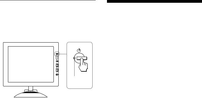
Self-diagnosis function
This monitor is equipped with a self-diagnosis function. If there is a problem with your monitor or computer(s), the screen will go blank and the 1 (power) indicator will either light up green or flash orange. If the 1 (power) indicator is lit in orange, the computer is in power saving mode. Try pressing any key on the keyboard or moving the mouse.
1 (power) indicator
If the 1 (power) indicator is green
1Turn off the AC power switch and disconnect the video signal cables from the INPUT1 and INPUT2 connectors of the media engine.
2Press the AC power switch twice to turn the monitor off and then on.
If all four color bars appear (white, red, green, blue), the monitor is working properly. Reconnect the video input cables and check the condition of your computer(s).
If the color bars do not appear, there is a potential monitor failure. Inform your authorized Sony dealer of the monitor’s condition.
If the 1 (power) indicator is flashing orange
Press the 1 (power) switch twice to turn the monitor off and then on.
If the 1 (power) indicator lights up green, the monitor is working properly.
If the 1 (power) indicator is still flashing, there is a potential monitor failure. Count the number of seconds between orange flashes of the 1 (power) indicator and inform your authorized Sony dealer of the monitor’s condition. Be sure to note the model name and serial number of your monitor. Also note the make and model of your computer and graphic board.
Specifications
LCD panel |
Panel type: a-Si TFT Active Matrix |
|
Picture size: 15 inch (38 cm) |
Input signal format |
RGB operating frequency* |
|
Horizontal: 30 – 61 kHz |
|
Vertical: 48 – 85 Hz |
|
(only XGA mode at 75 Hz) |
Resolution |
Horizontal: Max.1024 dots |
|
Vertical: Max.768 lines |
Input signal levels |
RGB video signal |
|
0.700 Vp-p, 75 Ω, positive |
|
SYNC signal |
|
TTL level, 2 kΩ, |
|
positive or negative |
|
Separate horizontal and vertical, |
|
or composite sync) |
|
0.3 Vp-p, 75Ω, negative |
|
(Sync on green) |
Audio output |
2W × 2 |
Headphones jack |
Stereo minijack |
|
Accepts impedance of 16 – 48 Ω |
AUDIO IN jack |
Stereo minijack |
|
Accepts impedance of 47 kΩ |
|
Accepts level 0.5 Vrms |
Power requirements |
100 – 240 V, 50 – 60 Hz, 0.55 – 0.3 A |
Power consumption |
Max. 35 W |
Operating temperature |
5 – 35 ° C |
Dimensions (width/height/depth) |
|
|
Display (upright): |
|
Approx. 356 × 347 × 185 mm |
|
(14 1/8 × 13 3/4 × 7 3/8 inches) |
|
Media engine (without stand): |
|
Approx. 45 × 180 × 180 mm |
|
(1 13/16 × 7 1/8 × 7 1/8 inches) |
|
Media engine (with stand): |
|
Approx. 94 × 185 × 180 mm |
|
(3 3/4 × 7 3/8 × 7 1/8 inches) |
Mass |
Display: |
|
Approx. 2.7 kg (5 lb 15 oz) |
|
Media engine (with stand): |
|
Approx. 0.85 kg (1 lb 14 oz) |
Plug & Play |
DDC1/DDC2B/DDC2Bi |
Accessories |
See page 8. |
*Recommended horizontal and vertical timing condition
•Horizontal sync width duty should be more than 4.8% of total horizontal time or 0.8 µs, whichever is larger.
•Horizontal blanking width should be more than 2.5 µsec.
•Vertical blanking width should be more than 450 µsec.
Design and specifications are subject to change without notice.
22

Table des matières
•Macintosh est une marque commerciale sous licence d’Apple Computer, Inc., déposée aux Etats-Unis et dans d’autres pays.
•Windowsâ et MS-DOS sont des marques commerciales déposées de Microsoft Corporation aux Etats-Unis et dans d’autres pays.
•IBM PC/AT et VGA sont des marques commerciales déposées d’IBM Corporation of the U.S.A.
•VESA et DDC ä sont des marques commerciales de Video Electronics Standard Association.
•ENERGY STAR est une marque déposée aux Etats-Unis.
•Tous les autres noms de produit mentionnés dans le présent mode d'emploi peuvent être des marques commerciales ou des marques commerciales déposées de leurs entreprises respectives.
•De plus, les symboles “ ä” et “ â” ne sont pas systématiquement mentionnés dans ce mode d’emploi.
Précautions. . . . . . . . . . . . . . . . . . . . . . . . . . . . . . . . . . . . . . . . . . . . 4 Pour exploiter le son clair du haut-parleur stéréo intégré . . . . . . . . . 5 Identification des composants et des commandes . . . . . . . . . . . . . . 6
Installation . . . . . . . . . . . . . . . . . . . . . . . . . . . . . . . . . . . . .8
Etape 1: Raccordez le moteur de médias à votre ordinateur. . . . . . 8 Etape 2: Raccordez l’écran et le moteur de médias . . . . . . . . . . . . 8 Etape 3: Branchez le câble d’alimentation . . . . . . . . . . . . . . . . . . . . 9 Etape 4: Mettez le moniteur et l’ordinateur sous tension . . . . . . . . . 9 Utilisation du haut-parleur stéréo . . . . . . . . . . . . . . . . . . . . . . . . . . 10 Sélection du signal d’entrée . . . . . . . . . . . . . . . . . . . . . . . . . . . . . . 10
Personnalisation de votre moniteur. . . . . . . . . . . . . . . .11
Pilotage par menu. . . . . . . . . . . . . . . . . . . . . . . . . . . . . . . . . . . . . . |
11 |
|
Réglage du contraste (CONTRASTE) . . . . . . . . . . . . . . . . . . . . . . |
12 |
|
Réglage du niveau de noir de l’image (LUMINOSITE) . . . . . . . . . . |
12 |
|
Suppression du scintillement ou du flou (PHASE/HORLOGE). . . . |
13 |
|
Réglage de la position de l’image |
|
|
(CENTRAGE H/CENTRAGE V) |
13 |
|
FR |
||
Affichage d’un signal de faible résolution à la résolution en cours |
|
|
(ZOOM). . . . . . . . . . . . . . . . . . . . . . . . . . . . . . . . . . . . . . . . . . . . . . |
14 |
|
Réglage de la température des couleurs (COULEUR). . . . . . . . . . |
14 |
|
Changement de la position du menu (POSITION MENU) . . . . . . . |
14 |
|
Réinitialisation des réglages (RESTAUR) . . . . . . . . . . . . . . . . . . . |
15 |
|
Réglages additionnels (Option) . . . . . . . . . . . . . . . . . . . . . . . . . . . |
15 |
|
Spécifications techniques. . . . . . . . . . . . . . . . . . . . . . . .17
Fonction d’économie d’énergie (capteur utilisateur/mode d’économie d’énergie) . . . . . . . . . . . . . . . . . . . . . . . . . . . . . . . . . . 17 Fonction de réglage automatique de la luminosité
(capteur de lumière) . . . . . . . . . . . . . . . . . . . . . . . . . . . . . . . . . . . . 18 Fonction de réglage automatique de la qualité de l’image . . . . . . . 18
Dépannage . . . . . . . . . . . . . . . . . . . . . . . . . . . . . . . . . . . .19
Messages affichés . . . . . . . . . . . . . . . . . . . . . . . . . . . . . . . . . . . . . 19 Symptômes de défaillances et remèdes. . . . . . . . . . . . . . . . . . . . . 20 Fonction d’autodiagnostic . . . . . . . . . . . . . . . . . . . . . . . . . . . . . . . . 22
Spécifications. . . . . . . . . . . . . . . . . . . . . . . . . . . . . . . . . .22
Appendix. . . . . . . . . . . . . . . . . . . . . . . . . . . . . . . . . . . . . . . i
Preset mode timing table . . . . . . . . . . . . . . . . . . . . . . . . . . . . . . . . . .i TCO’95 Eco-document . . . . . . . . . . . . . . . . . . . . . . . . . . . . . . . . . . . .i
3
Précautions
Avertissement sur les connexions d’alimentation
•Utilisez le câble d’alimentation fourni. Si vous utilisez un câble d’alimentation différent, assurez-vous qu’il est compatible avec la tension secteur locale.
Pour les clients aux Etats-Unis
Si vous n’employez pas le câble approprié, ce moniteur ne sera pas conforme aux normes FCC obligatoires.
Pour les clients au Royaume-Uni
Si vous utilisez le moniteur au Royaume-Uni, veuillez utiliser le câble d’alimentation adapté au Royaume-Uni.
Exemples de types de fiches
pour 100 à 120 V CA pour 200 à 240 V CA pour 240 V CA uniquement
L’appareil doit être installé à proximité d’une prise de courant aisément accessible.
Installation
N’installez pas et ne laissez pas le moniteur:
•A des endroits exposés à des températures extrêmes, par exemple à proximité d’un radiateur, d’un conduit de chauffage ou le rayonnement direct du soleil. L’exposition du moniteur à des températures extrêmes, comme dans l’habitacle d’une voiture parquée en plein soleil ou à proximité d’un conduit de chauffage, risque d’entraîner des déformations du châssis ou des dysfonctionnements.
•A des endroits soumis à des vibrations mécaniques ou à des chocs.
•A proximité d’appareils générant de puissants champs magnétiques, comme un téléviseur ou d’autres appareils électroménagers.
•A des endroit soumis à des quantités inhabituelles de poussière, de saletés ou de sable, par exemple à côté d’une fenêtre ouverte ou d’une porte donnant sur l’extérieur. En cas d’installation temporaire à l’extérieur, veillez à prendre les précautions requises contre la poussière et les saletés en suspension dans l’air. Faute de quoi des dommages irréparables risquent de se produire.
Manipulation de l’écran LCD
•Ne laissez pas l’écran LCD face au soleil, car vous risquez sinon de l’endommager. Faites donc attention si vous installez le moniteur à côté d’une fenêtre.
•N’appuyez pas sur et veillez à ne pas érafler la surface de l’écran LCD. Ne posez pas d’objets lourds sur l’écran LCD. Vous risquez sinon d’altérer l’uniformité de l’écran ou de provoquer un dysfonctionnement de l’écran LCD.
•Lorsque le moniteur est employé dans un environnement froid, il est possible qu’une image rémanente apparaisse sur l’écran. Il ne s’agit pas d’un dysfonctionnement. L’écran recouvre sa condition normale dès que la température est revenue à un niveau normal.
•Si une image fixe reste affichée pendant une longue durée, il se peut qu’une image rémanente apparaisse pendant un certain temps. Cette image rémanente finira par disparaître.
•Le panneau LCD s’échauffe en cours d’utilisation. Il ne s’agit pas d’un dysfonctionnement.
A propos des points lumineux ou des points noirs
Il est possible que des points lumineux (rouges, bleus ou verts) ou des points noirs apparaissent sur l’écran LCD. Il ne s’agit pas d’un dysfonctionnement. L’écran LCD est fabriqué en faisant appel à des technologies de haute précision et plus de 99,99 % des éléments d’image sont intacts. Il est cependant possible que certains éléments d’image n’apparaissent pas ou que certains éléments d’image apparaissent de manière constante.
Entretien
•Débranchez le câble d’alimentation de la prise secteur avant de procéder au nettoyage de votre moniteur.
•Nettoyez l’écran LCD avec un chiffon doux. Si vous utilisez un liquide de nettoyage pour le verre, n’utilisez pas de nettoyant contenant une solution antistatique ou tout autre additif similaire, car vous risquez sinon de griffer le revêtement de l’écran LCD.
•Nettoyez le châssis, le panneau et les commandes à l’aide d’un chiffon doux légèrement imprégné d’une solution détergente neutre. N’utilisez aucun type de tampon abrasif, de poudre à récurer ou de solvant tel que de l’alcool ou de la benzine.
•Ne frottez pas, ne touchez pas et ne tapotez pas la surface de l’écran avec des objets pointus ou abrasifs comme un stylo à bille ou un tournevis. Ce type de contact risque de rayer le tube image.
•Sachez qu’une détérioration des matériaux ou du revêtement de l’écran LCD risque de se produire si le moniteur est exposé à des solvants volatiles comme des insecticides ou en cas de contact prolongé avec des objets en caoutchouc ou en vinyle.
Transport
•Débranchez tous les câbles du moniteur avant de le transporter. Pour transporter cet écran, saisissez-le fermement des deux mains au niveau du support et de la base. Utilisez également les deux mains pour transporter le moteur de médias. Si vous laissez tomber le moniteur, vous risquez de vous blesser ou d’endommager le moniteur.
•Pour transporter ce moniteur en vue de réparations ou de son expédition, utilisez le carton et les matériaux de conditionnement originaux.
Remplacement du tube fluorescent
Un tube fluorescent de conception spéciale est installé dans ce moniteur comme source lumineuse. Si l’écran s’assombrit, est instable ou ne s’allume pas, remplacez le tube fluorescent. Pour le remplacement du tube fluorescent, consultez votre revendeur Sony.
Elimination du moniteur
•N’éliminez pas ce moniteur avec les ordures ménagères.
•Le tube fluorescent utilisé dans ce moniteur contient du mercure. L’élimination de ce moniteur doit être effectuée conformément aux réglementations des autorités locales compétentes en matière de propreté publique.
4
Réglage de l’inclinaison et de la hauteur
Cet écran peut être ajusté suivant les angles illustrés ci-dessous.
90°
40°
50° |
50° |
Pour ajuster les angles, saisissez le panneau LCD des deux mains par le bord inférieur comme illustré ci-dessous. Basculez le panneau LCD vers l’arrière, puis soulevez panneau LCD à la hauteur d’écran voulue et ajustez-en ensuite l’inclinaison. Lors du réglage de la hauteur et de l’inclinaison, procédez de façon lente et délicate en veillant à ne pas cogner le panneau LCD contre le bureau ou la base du support d’écran.
m
Pour utiliser l’écran confortablement
Cet écran est conçu de manière à ce que vous puissiez le régler suivant un angle de visualisation confortable. Ajustez l’angle de visualisation de votre écran en fonction de la hauteur du bureau et de votre chaise et de manière à ce que l’écran ne vous réfléchisse pas la lumière dans les yeux.
Pour exploiter le son clair du hautparleur stéréo intégré
Cet écran est équipé d’un haut-parleur stéréo intégré dans la base du support d’écran.
Nous vous conseillons de positionner le panneau LCD légèrement
àl’écart du support d’écran. Les aiguës diffusées par les hautparleurs risquent d’être étouffées par le panneau LCD s’il est positionné directement au-dessus du support. Veillez à ne pas laisser tomber d’objets métalliques dans les ouïes des hautparleurs, car les haut-parleurs génèrent un champ magnétique. De même, le champ magnétique risque d’affecter les données enregistrées sur des bandes magnétiques et des disquettes. Veillez
àconserver les appareils d’enregistrement magnétique, les cassettes et les disquettes à l’écart des ouvertures du haut-parleur. Un conduit est présent à l’arrière du support d’écran afin d’accentuer les graves. Veillez à ne pas obstruer ce conduit avec du papier ou tout autre objet de manière à garantir un son clair.
FR
Conduits
Ecartez légèrement le panneau LCD de la base.
Haut-parleur
5
Identification des composants et des commandes
Pour plus de détails, reportez-vous aux pages entre parenthèses.
Ecran LCD
MENU
INPUT
1
2
OK
Avant |
Arrière |
SYSTEM CONNECTER
1Commutateur et indicateur 1 (alimentation)
(pages 9, 17, 22)
Ce commutateur sert à la mise sous et hors tension de l’écran. L’indicateur s’allume en vert lorsque le moniteur est sous tension. L’indicateur clignote en vert et en orange lorsque le moniteur est en mode de faible consommation énergétique et s’allume en orange lorsque le moniteur est en mode d’économie d’énergie.
2Capteur de luminosité et détecteur d’utilisateur (pages 16, 17, 18)
Ces capteurs mesurent la luminosité ambiante et détectent la présence d’un utilisateur face à l’écran. Veillez à ne pas recouvrir le capteur de papier, etc.
3Touche MENU (menu) (page 12)
Cette touche active l’affichage du menu principal.
4Touche 6 (contraste) (page 12)
Cette touche active l’affichage du menu CONTRASTE.
5Touche 8 (luminosité) (page 12)
Cette touche active l’affichage du menu LUMINOSITE.
6Touches 2 (volume) +/– et M(+)/m(–) (pages 10, 12)
Ces touches activent l’affichage du menu VOLUME et servent de touches fléchéesM(+)/m(–) pour sélectionner des
paramètres de menu et effectuer des réglages.
7Touche INPUT (entrée) et OK, et indicateur (pages 10, 12)
Cette touche sélectionne le signal d’entrée vidéo INPUT 1 ou INPUT 2 (connecteurs HD15 (RVB)). Le signal d’entrée et l’indicateur d’entrée correspondant changent chaque fois que vous appuyez sur cette touche.
Cette touche sert également de touche OK lorsque le menu est affiché à l’écran.
8Haut-parleur stéréo (page 10)
Ce haut-parleur diffuse les signaux audio sous forme de sons.
9Conduits
Ces conduits servent à renforcer les graves du haut-parleur.
0SYSTEM CONNECTOR (CONNECTEUR DU SYSTEME) (page 8)
Ce connecteur entre les signaux du moteur de médias lorsque l’écran et le moteur de médias sont raccordés au moyen de câble de connexion système.
qa Prise pour casque d’écoute (page 10)
Cette prise sort les signaux audio vers un casque d’écoute.
6
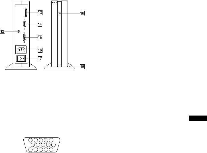
Moteur de médias
SYSTEM CONNECTER (TO DISPLAY)
INPUT 1
AUDIO IN
INPUT 2
qs Prise AUDIO IN (page 10)
Cette prise entre les signaux audio lorsqu’il est raccordé à la prise de sortie audio de l’ordinateur ou d’un autre appareil audio.
qd SYSTEM CONNECTOR (CONNECTEUR DU
SYSTEME) (TO DISPLAY) (page 8)
Ce connecteur sort les signaux du moteur de médias lorsque l’écran et le moteur de médias sont raccordés au moyen de câble de connexion système.
qf Connecteur 1 d’entrée HD15 (RVB) (INPUT1)
(page 8)
Ce connecteur entre les signaux vidéo RVB (0,700 Vp-p, positifs) et les signaux SYNC.
|
5 |
|
4 |
3 |
2 |
1 |
|
10 |
9 |
8 |
7 |
6 |
|
|
15 |
14 |
13 12 |
11 |
||
|
|
|
|
|
|
|
Broche n° |
Signal |
|
|
|
|
|
|
|
|
|
|
|
|
1 |
Rouge |
|
|
|
|
|
|
|
|
|
|
|
|
2 |
Vert |
|
|
|
|
|
|
(Synchronisation sur le vert) |
|||||
|
|
|
|
|
|
|
3 |
Bleu |
|
|
|
|
|
|
|
|
|
|
|
|
4 |
ID (masse) |
|
|
|
|
|
|
|
|
|
|
||
5 |
Masse DDC* |
|
|
|
||
|
|
|
|
|||
6 |
Masse du rouge |
|
|
|||
|
|
|
|
|
||
7 |
Masse du vert |
|
|
|
||
|
|
|
|
|
||
8 |
Masse du bleu |
|
|
|
||
|
|
|
|
|
|
|
9 |
DDC + 5V* |
|
|
|
|
|
|
|
|
|
|
|
|
10 |
Masse |
|
|
|
|
|
|
|
|
|
|
|
|
11 |
ID (masse) |
|
|
|
|
|
|
|
|||||
12 |
Données bidirectionnelles (SDA)* |
|||||
|
|
|
|
|||
13 |
Synchronisation H |
|
|
|||
|
|
|
|
|||
14 |
Synchronisation V |
|
|
|||
|
|
|||||
15 |
Horloge de données (SCL)* |
|||||
|
|
|
|
|
|
|
* DDC (Display Data Channel) est une norme de VESA.
qg Connecteur 2 d’entrée HD15 (RVB) (INPUT2)
(page 8)
Ce connecteur entre les signaux vidéo RVB (0,700 Vp-p, positifs) et les signaux SYNC. L’assignation des broches est la même que pour le connecteurqf.
qh Connecteur AC IN (page 9)
Ce connecteur assure l’alimentation secteur du moniteur.
qj Commutateur d’alimentation secteur (page 9)
Ce commutateur sert à la mise sous et hors tension du moniteur. Lorsque le commutateur d’alimentation secteur est actionné, l’écran se met automatiquement sous tension.
qk Indicateur d’alimentation secteur (page 17)
Cet indicateur s’allume en vert lorsque le moteur de médias est sous tension. Cet indicateur s’allume en rouge lorsque l’écran est hors tension et que le moteur de médias est sous tension. L’indicateur s’allume en orange lorsque le moniteur se trouve en mode d’économie d’énergie.
ql Support du moteur de médias
Ce support sert à installer le moteur de médias verticalement.
Attention
Veillez à installer le moteur de média verticalement comme illustré à gauche. L’installation du moteur de média en position plate risque de bloquer les ouïes de ventilation et de provoquer un dysfonctionnement.
FR
7
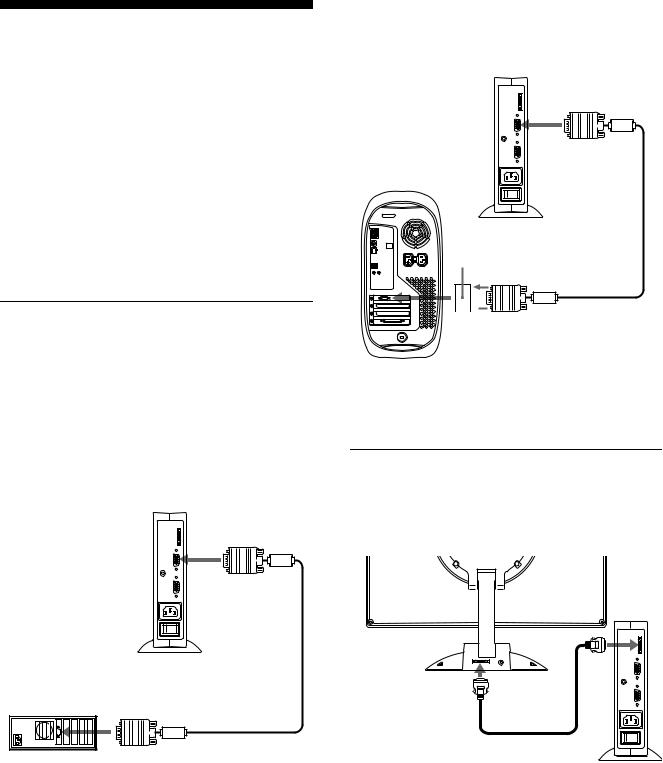
Installation
Avant d’utiliser votre moniteur, vérifiez si les accessoires suivants se trouvent bien dans le carton d’emballage:
•Ecran LCD
•Moteur de médias
•Support du moteur de médias
•Câble d’alimentation
•Câble de connexion système (2 m) (type de câble applicable: DP-2)
•Câble de signal vidéo HD15 (RVB)
•Câble audio (minifiche stéréo)
•Adaptateur Macintosh
•Windows Monitor Information Disk/Utility Disk
•Macintosh Utility Disk
•Carte de garantie
•Remarques pour les utilisateurs Macintosh
•Ce mode d’emploi
Etape 1: Raccordez le moteur de médias à votre ordinateur
Mettez le moteur de médias et l’ordinateur hors tension avant de procéder aux connexions.
Remarque
Ne touchez pas les broches du connecteur du câble de signal vidéo, car vous risquez sinon de plier les broches.
xRaccordement à un ordinateur IBM PC/AT ou compatible
vers le connecteur INPUT1 ou INPUT2
|
vers la sortie vidéo |
|
Câble de signal vidéo |
Ordinateur IBM PC/AT |
HD15 (RVB) (fourni) |
ou compatible |
|
xRaccordement à un ordinateur Macintosh ou compatible
Utilisez l’adaptateur Macintosh fourni.
vers le connecteur INPUT1 ou INPUT2
Adaptateur Macintosh (fourni)*
 Câble de signal vidéo vers la sortie vidéo HD15 (RVB) (fourni)
Ordinateur Macintosh ou compatible
*Pour plus de détails, reportez-vous aux “Remarques pour les utilisateurs Macintosh” fournies.
Etape 2: Raccordez l’écran et le moteur de médias
Mettez l’écran et le moteur de médias hors tension avant de procéder aux connexions.
vers le SYSTEM |
vers le SYSTEM |
CONNECTOR |
CONNECTOR |
(connecteur système) |
(connecteur système) |
de l’écran |
du moteur de médias |
|
Câble de connexion |
|
système (2 m) (fourni) |
Attention
Veillez à installer le moteur de média verticalement comme illustré ci-dessus. L’installation du moteur de média en position plate risque de bloquer les ouïes de ventilation et de provoquer un dysfonctionnement.
Remarque
Branchez le câble en le saisissant par la fiche.
8
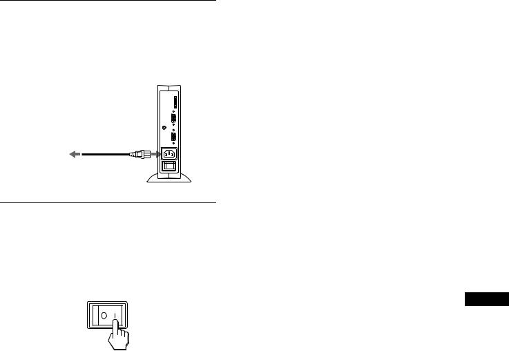
Etape 3: Branchez le câble d’alimentation
Le moteur de médias, l’écran et l’ordinateur étant hors tension, branchez d’abord le câble d’alimentation au moteur de médias et ensuite sur une prise secteur.
|
vers AC IN |
vers une prise |
|
secteur |
Câble d’alimentation |
|
|
|
(fourni) |
Etape 4: Mettez le moniteur et l’ordinateur sous tension
1Mettez le moteur de médias sous tension.
L’écran se met automatiquement sous tension. Les indicateurs du moteur de médias et de l’écran s’allument en vert.
2 Mettez l’ordinateur sous tension.
L’installation de votre moniteur est à présent terminée. Si nécessaire, utilisez les commandes du moniteur pour régler l’image.
Si aucune image n’apparaît sur l’écran
•Vérifiez si le moniteur est correctement raccordé à l’ordinateur.
•Vérifiez si le moteur de médias est sous tension.
•Si l’ndication PAS ENTREE VIDEO apparaît sur l’écran, l’ordinateur est en mode d’économie d’énergie. Essayez d’appuyer sur n’importe quelle touche du clavier ou de déplacer la souris.
•Si CABLE DECONNECT apparaît sur l’écran, essayez de changer de signal d’entrée (page 10) et vérifiez que le câble d’entrée vidéo est branché correctement.
•Si l’indication HORS PLAGE DE BALAYAGE apparaît sur l’écran, reconnectez l’ancien moniteur. Réglez ensuite la carte graphique de l’ordinateur de façon à ce que la fréquence horizontale soit comprise entre 30 – 61 kHz, et la fréquence verticale entre 48 – 85 Hz (uniquement en mode XGA à 75 Hz).
Pour des informations plus détaillées sur les messages à l’écran, voir “Symptômes de défaillances et remèdes” à la page 20.
Pour les clients utilisant Windows 95/98
Pour maximiser le potentiel de votre moniteur, installez sur votre ordinateur le fichier d’information sur le nouveau modèle à partir Windows Monitor Information Disk.
Ce moniteur satisfait à la norme Plug & Play “VESA DDC”. Si votre carte PC/graphique satisfait à DDC, sélectionnez “Plug & Play Monitor (VESA DDC)” ou la désignation de ce moniteur comme type de moniteur dans le “Control Panel” de Windows 95/98. Si votre PC/carte graphique présente des difficultés à communiquer avec ce moniteur, chargez le Windows Monitor Information Disk et sélectionnez le nom de modèle
correspondant à ce moniteur comme type de moniteur.
FR
Pour les clients utilisant Windows NT4.0
La configuration du moniteur sous Windows NT4.0 est différente de Windows 95/98 et ne nécessite pas la sélection du type de moniteur. Reportez-vous aux instructions d’utilisation de Windows NT4.0 pour des informations plus détaillées sur le réglage de la résolution, du taux de régénération et du nombre de couleurs.
Réglage de la résolution du moniteur et du nombre de couleurs
Réglez la résolution du moniteur et le nombre de couleurs en vous référant au mode d’emploi de votre ordinateur. Le nombre de couleurs peut varier en fonction de votre ordinateur et de votre carte vidéo. Réglez la palette de couleurs et le nombre de couleurs comme suit:
•High Color (16 bit) t 65.536 couleurs
•True Color (24 bit) t environ 16,77 millions de couleurs En mode True Color (24 bit), la vitesse peut être plus lente.
9
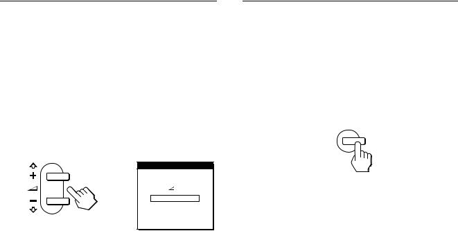
Utilisation du haut-parleur stéréo
Vous pouvez écouter de la musique, des sons et d’autres fichiers audio via le haut-parleur stéréo de votre moniteur.
Raccordez la prise AUDIO IN à la prise de sortie audio de votre ordinateur ou d’un autre appareil audio à l’aide du câble audio fourni (minifiche stéréo).
Réglage du volume
Le réglage du volume se fait via un menu VOLUME distinct du menu principal (page 11).
1Appuyez sur les touches 2 +/–.
Le menu VOLUME apparaît sur l’écran.
VOL UME
4 0
2Appuyez sur les touches 2 +/– pour régler le volume.
Le menu disparaît automatiquement au bout d’environ 3 secondes.
Utilisation de la prise pour casque d’écoute
Vous pouvez écouter les signaux audio de votre ordinateur ou d’un autre appareil audio à l’aide d’un casque d’écoute. Raccordez votre casque d’écoute à la prise pour casque d’écoute. Le haut-parleur est désactivé dès que vous branchez un casque d’écoute sur la prise pour casque d’écoute. Ajustez le volume du casque d’écoute à l’aide du menu VOLUME.
Remarques
•Vous ne pouvez pas régler le volume lorsque le menu principal est affiché sur l’écran.
•Lorsque votre moniteur se trouve en mode de faible consommation énergétique ou en mode d’économie d’énergie, aucun son n’est diffusé par le haut-parleur.
Sélection du signal d’entrée
Vous pouvez raccorder deux ordinateurs à ce moniteur via les connecteurs INPUT 1 et INPUT 2. Pour sélectionner l’un des deux ordinateurs, utilisez la touche INPUT.
Appuyez sur la touche INPUT.
Le signal d’entrée et l’indicateur d’entrée correspondant,
“1” (INPUT 1) ou “2” (INPUT 2), changent chaque fois que vous appuyez sur cette touche.
INPUT
1
2
OK
Remarques
•Vous ne pouvez pas sélectionner le signal d’entrée lorsque le menu principal est affiché sur l’écran.
•Si aucun signal n’est entré via le connecteur sélectionné, l’indication PAS ENTREE VIDEO ou CABLE DECONNECT apparaît sur l’écran. Au bout de quelques secondes, le moniteur passe en mode d’économie d’énergie. Si cela se produit, sélectionnez l’autre connecteur à l’aide de la touche INPUT.
10
 Loading...