


 Loading...
4-653-886-11(1)
SDT-D11000/D9000
DDS Drive Unit
Operator’s Guide –––––––––page 2
Mode d’emploi –––––––––––page 21
Benutzerhandbuch –––––––Seite 39
Guía del operador ––––––––página 58
© 2001 Sony Corporation
Safety Regulations
Owner’s Record
The model and serial numbers are located on the bottom. Record the serial number in the space provided below.
Refer to them whenever you call upon your Sony dealer regarding this product.
Model No. |
Serial No. |
Information
WARNING
To prevent fire or shock hazard, do not expose the unit to rain or moisture.
To avoid electrical shock, do not open the cabinet. Refer servicing to qualified personnel only.
For the customers in the U.S.A.
You are cautioned that any changes or modifications not expressly approved in this manual could void your authority to operate this equipment.
WARNING
Note: This equipment has been tested and found to comply with the limits for a Class B digital device, pursuant to Part 15 of the FCC Rules. These limits are designed to provide reasonable protection against harmful interference in a residential installation. This equipment generates, uses and can radiate radio frequency energy and, if not installed and used in accordance with the instructions, may cause harmful interference to radio communications. However, there is no guarantee that interference will not occur in a particular installation. If this equipment does cause harmful interference to radio or television reception, which can be determined by turning the equipment off and on, the user is encouraged to try to correct the interference by one or more of the following measures:
•Reorient or relocate the receiving antenna.
•Increase the separation between the equipment and receiver.
•Connect the equipment into an outlet on a circuit different from that to which the receiver is connected.
•Consult the dealer or an experienced radio/TV technician for help.
2

CAUTION
The mains plug on this equipment must be used to disconnect mains power. Please ensure that the socket outlet is installed near the equipment and shall be easily accessible.
NOTICE
Use the power cord set approved by the appropriate testing organization for the specific countries where this unit is to be used.
If you have any questions about this product, you may call: Sony Technical Support, 1-800-588-3847 or write to :
Sony Technical Support, 3300 Zanker Road, San Jose, CA 95134, 1940. U.S.A.
DECLARATION |
OF CONFORMITY |
Trade Name: |
Sony |
Model No: |
SDT-D11000/D9000 |
Responsible Party: |
Sony Electronics, Inc. |
Address: |
680 Kinderkamack Road, Oradell NJ 07649 U.S.A. |
Telephone: |
201-930-6972 |
This device complies with part 15 of the FCC Rules.
Operation is subject to the following two conditions:
(1)This device may not cause harmful interference.
(2)This device must accept any interference received, including interference that may cause undesired operation.
This device requires shielded interface cables to comply with FCC emission limits.
English
3

Table of Contents
Part 1
Introduction
Part 2
Preparation
Part 3
Operation
Part 4
Care and
Maintenance
Appendix
How to Use this Guide ...................................................................... |
5 |
About DDS Drives ............................................................................. |
6 |
Features .................................................................................................... |
6 |
Useable Cartridges ................................................................................... |
7 |
System Components ................................................................................ |
7 |
Part Names and Functions ............................................................... |
8 |
Front Panel ............................................................................................... |
8 |
Rear Panel .............................................................................................. |
10 |
Supplied Items ................................................................................. |
11 |
Interconnections ............................................................................. |
11 |
SCSI ID Setting ................................................................................ |
12 |
How to use the DDS Drive .............................................................. |
13 |
Cartridge Removal ................................................................................. |
14 |
Taking Care of the Drive ................................................................. |
15 |
Safety Considerations ............................................................................ |
15 |
Avoiding Damage .................................................................................. |
15 |
Taking Care of Cartridges .............................................................. |
17 |
Use Precautions ..................................................................................... |
17 |
Storage Precautions ............................................................................... |
17 |
Head Cleaning ................................................................................. |
18 |
How to Clean ......................................................................................... |
18 |
Specifications (SDT-D11000) ......................................................... |
19 |
Specifications (SDT-D9000) ........................................................... |
20 |
4 Table of Contents

How to Use this Guide
This Guide describes the DDS Drive Unit SDT-D11000/D9000 , and how to take care of it. Please read it carefully before using the unit, and keep it handy for future reference.
The Guide consists of four parts, plus the specifications. Refer to the parts that relate to your use of the drive.
Part 1 describes the features of the drive, its system components, and the name and function of each part.
Part 2 describes the necessary connections between the drive and the host computer. If other SCSI devices are being used, you may need to change the SCSI ID setting. Read this part if you are installing the drive.
Part 3 describes how to use the drive, including how to turn it on, and how to insert and remove cartridges. Read this part if you are going to operate the drive.
Part 4 describes how to take care of the drive and cartridges, and how to clean the drive heads. Read this part before using the drive.
The Specifications Appendix provides the major specifications of the
SDT-D11000/D9000.
5

 Part 1. Introduction
About DDS Drives
The SDT-D11000 is an external DDS drive unit that uses data cartridges conforming to the DDS-4 format. The SDT-D9000 is an external DDS drive unit that uses data cartridges conforming to the DDS-3 format. The SDTD11000 supports DDS-1, DDS-2, DDS-3 and DDS-4 formats. The SDTD9000 supports DDS-1, DDS-2 and DDS-3 formats.
Features
The DDS Drive Unit SDT-D11000 has the following features:
•The Digital Data Storage format provides a huge data storage capacity on DDS-1/DDS-2/DDS-3/DDS-4 data cartridges.
•Read After Write Function and third-level error correction code guarantee high data reliability.
•Data compression provides 40 gigabytes of storage on 150 m tape-length cartridge.*1
The native capacity is 20 gigabytes of storage on 150 m tape-length cartridge.
•Stored data are automatically checked for compression. •Embedded wide ultra SCSI interface.
(LVD/SE automatically switchable)
• Supports SCSI-2 sequential-access devices command set.
•Read/Write operation is available with DDS-1, DDS-2, DDS-3 and DDS-4 formats.
The DDS Drive Unit SDT-D9000 has the following features:
•The Digital Data Storage format provides a huge data storage capacity on DDS-1/DDS-2/DDS-3 data cartridges.
•Read After Write Function and third-level error correction code guarantee high data reliability.
•Data compression provides 24 gigabytes of storage on 125 m tape-length cartridge.*1
The native capacity is 12 gigabytes of storage on 125 m tape-length cartridge.
•Stored data are automatically checked for compression.
•The SCSI-2 (ANSI SCSI-2 X3T9.2/86-109 REV. 10C) interface is fully supported for host computer access.
•Read/Write operation is available with DDS-1, DDS-2 and DDS-3 formats.
*1 This is assuming 2 : 1 compression ratio.
The degree of data compression attained while recording data varies according to system environment and data type.
6 Part 1. Introduction
Useable Cartridges
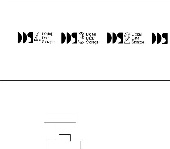
Data cartridges used with the SDT-D11000 must be marked with the DDS-1, DDS-2, DDS-3 or DDS-4 logo. The SDT-D9000 can only be used with data cartridges marked with DDS-1, DDS-2 or DDS-3 logo.
DDS-4 Logo |
DDS-3 Logo |
DDS-2 Logo |
DDS-1 logo |
Caution
Be sure to use only the cartridges designed specifically for DDS (do not use
DAT cartridges for music).
System Components
The SDT-D11000 connects to the host computer via a wide ultra SCSI interface.
The SDT-D9000 connects to the host computer via a SCSI-2 interface.
Host Computer
SDT-D11000: Up to 15 peripherals
|
|
|
|
|
|
|
|
|
|
|
|
|
|
|
|
|
|
|
|
|
|
|
|
|
|
|
|
|
|
|
|
|
|
|
|
|
|
|
|
|
|
|
|
|
|
SDT-D11000/D9000 |
|
|
|
|
|
|
Peripheral Devices |
|
|
|
||||||||||||
|
|
|
Figure 1-1. Example of System Components |
|
|
|
||||||||||||||||
Part 1. Introduction |
7 |

Part Names and Functions
Front Panel
|
|
1 |
2 |
|
|
|
POWER |
BUSY |
TAPE |
STATUS |
|
3 4 5 |
6 |
7 |
|
Figure 1-2. Front panel |
|
1DDS Data Cartridge Receptacle
See page 13 for information on inserting and removing a DDS data cartridge.
2POWER Indicator
Lights while the drive is on.
3BUSY Indicator
Lights when data is being transferred through the SCSI interface. This indicator also lights under the following conditions:
Drive is reading or writing normally: repeated blinking (same on-off interval).
4TAPE Indicator
When a DDS cartridge is installed, this indicator lights. This also lights under the following conditions:
Inserting and removing a cartridge: repeated blinking (same on-off interval).
Cartridge deteriorated: |
alternating long-short blinking. |
8 Part 1. Introduction
5STATUS Indicator
Lights when an inserted cartridge is write-protected. This indicator also lights under the following conditions:
Drive needs cleaning: |
repeating long-on, short-off |
|
blinking. |
|
|
End of Tape during cleaning: |
repeating blinking (same on-off |
|
interval). |
|
|
Drive Malfunctioning: |
repeating short-on (once or twice), |
|
long-off blinking. |
|
|
6EJECT Button
Push to remove a data cartridge from the drive.
7POWER Switch
Press to turn the drive on or off.
Part 1. Introduction |
9 |
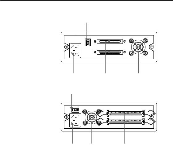
Rear Panel
SDT-D11000
1
2 3 4
SDT-D9000
1
2 4 3
Figure 1-3. Rear Panel
1Rotary Selector Switch
SCSI ID selector.
2AC IN Connector
Connect the supplied power cable here.
3SCSI Connector
Connects to the SCSI bus connector of the host computer or another SCSI peripheral.
4 Cooling Fan
10 Part 1. Introduction
 Part 2. Preparation
After you confirm that you have all of the required accessories for your installation, connect the drive to the host computer, and select the SCSI ID with the rotary switch on the rear panel.
Supplied Items
When you first open the box, make sure it contains the following items. Contact your supplier if anything is missing or broken.
•DDS Drive Unit •Power Cable •Operator’s Guide
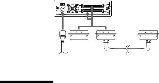
Interconnections
SDT-D11000
The SCSI bus allows connection of up to fifteen peripherals to the host computer. Use a SCSI cable with a 68 pin connector.
Precautions
•Switch off the host computer and peripherals before connecting the SCSI cable.
•Make sure the SCSI connectors are pressed tightly together.
•If this unit is the last (or only) device on the SCSI bus, make sure to connect a SCSI bus terminator to the open connector.
•The total length of the SCSI cable(s) between the host computer and the last device should be less than 3 meters.*1
•To set up the LVD configuration, you need:
1) Host PC with the LVD SCSI Board, 2) only LVD devices on the SCSI bus, and 3) LVD/SE switchable terminator.
AC power
Figure 2-1. Interconnections
*1 When using high-speed data transfer with the SDT-D11000, it is recommended that total length of the SCSI cable not exceed 1.5 m (SE) or 12 m (LVD).
Part 2. Preparation 11
SDT-D9000
The SCSI bus allows connection of up to seven peripherals to the host computer. Use a SCSI cable with a full pitch 50 pin connector.
Precautions
•Switch off the host computer and peripherals before connecting the SCSI cable.
•Make sure the SCSI connectors are pressed tightly together.
•If this unit is the last (or only) device on the SCSI bus, make sure to connect a SCSI bus terminator to the open connector.
•The total length of the SCSI cable(s) between the host computer and the last device should be less than 6 meters. *2
AC power |
Figure 2-2. Interconnections |
*2 When using high-speed data transfer with the SDT-D9000, it is recommended that total length of the SCSI cable not exceed 3 m.
SCSI ID Setting
The SCSI ID is set by the rotary switch on the rear panel. Press the + or – buttons to move the number up or down, respectively.
As shipped from the factory, the SCSI ID is set to 0. Press the switch buttons, if necessary, to select the SCSI ID number you require.
Precautions
•The SCSI ID must be different from IDs of the other peripherals on the SCSI bus.
•As shipped from the factory, SCSI parity is enabled and Term power is ON.
A SCSI bus terminator must be connected to the SCSI bus before use.
•Before changing the SCSI ID setting, be sure to turn off the power with the POWER switch on the front panel.
12 Part 2. Preparation
 Part 3. Operation
This section describes how to use the DDS drive, and how to handle data cartridges.
How to use the DDS Drive
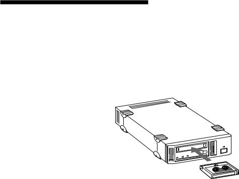
1Press the POWER switch on the front panel.
The POWER indicator should light, and the STATUS, BUSY and TAPE indicators should blink as the self-test is performed.
2When the three indicators stop blinking, you can insert a data cartridge as shown below. The TAPE indicator will blink, and if the cartridge is write-protected, the STATUS indicator will light.
Figure 3-1. Inserting a data cartridge
3Computer software controls the reading and writing of tapes. While reading or writing, the BUSY indicator blinks.
Part 3. Operation 13

Cartridge Removal
Press the EJECT button.
The cartridge ejects automatically.
Figure 3-2. Press the EJECT button
Caution
Do not push the EJECT button while the BUSY indicator is blinking: to do so may destroy data on the tape.
14 Part 3. Operation

 Part 4. Care and Maintenance
Taking Care of the Drive
Safety Considerations
■ Power
•Be sure to use only 100-240 V AC.
•Avoid plugging into the same outlet as high-current equipment like copiers or shredders.
■ Power Cable Precautions
•Do not crush the cable or place heavy items on it. If the cable insulation appears worn or broken, do not use the cable.
•Always unplug the cable by holding the plug: never pull the cable itself, as it will break.
•If the drive is not being used for a long time, unplug the cable from the outlet.
Avoiding Damage
■ Avoid shock and vibration
Intense shock, such as from dropping the drive, will damage it.
■ Environmental considerations
Do not store or use the drive in locations subject to:
• high humidity |
• excessive dust |
• high temperature |
• intense vibration |
• direct sunlight |
• sudden changes in temperature |
■ Proper ventilation
To avoid overheating, install the drive where it will have free air circulation around the case, and do not cover it during operation. The drive can malfunction if the internal temperature rises too high.
■ Avoid sudden changes in temperature
If the drive is moved from a cool place to a warm place, or if the room temperature suddenly rises, moisture may condense inside the case. After a sudden change in temperature, wait at least one hour before turning the drive on. If the drive is turned on with condensation inside, and a cartridge is installed, the drive or the tape can be damaged.
Part 4. Care and Maintenance 15
■ Abnormal occurrences
If the drive behaves abnormally, or if it begins to smell or smoke, immediately unplug it from the wall outlet and contact your supplier for assistance.
■ Cabinet cleaning
Wipe the cabinet with a soft dry cloth. For heavy dirt, wipe with a soft cloth moistened with a gentle liquid soap, then wipe again with a soft dry cloth. Do not use alcohol, paint thinner, bug sprays or other volatile solvents, as they can damage the finish.
16 Part 4. Care and Maintenance
Taking Care of Cartridges
Use Precautions
•Avoid heavy vibration and dropping.
•The shutter on the face of the cartridge is opened automatically when it is inserted into the drive. Do not open the shutter by hand, as touching the tape may damage it.
•The cartridge was carefully aligned during assembly at the factory. Please do not try to open it or take it apart.
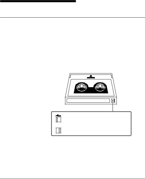
•The write-protect switch on the face of the cartridge prevents the tape from being written to or accidentally erased. If you do not need to write to the tape, move this switch to the write-protect position (in the direction of the arrow).
Using your fingernail, push the switch in the direction of the arrow to protect the tape from writing or accidental erasure.
Return the switch to its original position to re-enable writing.
Figure 4-1. Write-protect switch
•In case of a sudden change in temperature, condensation may interfere with reading and writing to a tape.
•Avoid unnecessary insertion and removal of cartridges if you do not need to write or read a tape.
•When finished using the drive, remove the cartridge.
Storage Precautions
•Keep cartridges in their cases when not in the drive.
•Avoid storing cartridges in dusty places, in direct sunlight, near heaters or air conditioners, or in humid locations.
•Do not place cartridges on the dashboard or in a storage tray in a car.
Part 4. Care and Maintenance 17

Head Cleaning
To keep the DDS drive in top condition, clean the head as needed, using the proper head cleaning cartridge (sold separately). When the head needs cleaning, the STATUS indicator will blink.
How to Clean
1Load the head cleaning cartridge (DGD15CL) into the DDS drive. Cleaning starts automatically.
2After about 10 seconds, cleaning will stop and the cartridge will eject automatically.
One head cleaning cartridge can be used about 90 times.
Notice
Do not rewind the cleaning cartridge and reuse it. When you reach the end of the cartridge, dispose it and buy a new one.
18 Part 4. Care and Maintenance


 Appendix
Specifications (SDT-D11000)
■ Performance
Storage Capacity |
40 GB compressed |
|
(with 150 m DDS-4 tape)*1 |
|
20 GB uncompressed |
|
(with 150 m DDS-4 tape) |
Bit Error Rate |
less than 10 -15 |
Data Transfer Rate |
1.18 MB/s uncompressed |
(TAPE) |
2.36 to 4.72 MB/s compressed |
Burst Data Transfer Rate |
14 MB/s maximum, asynchronous |
(SCSI) |
40 MB/s maximum, synchronous |
Initialize Time |
less than 1 seconds |
Load Time |
less than 24 seconds |
Unload Time |
less than 20 seconds |
Rewind Time |
less than 80 seconds (with 150 m tape) |
■ Operating Environment
Operating |
Temperature: |
10 to 35 °C |
|
Humidity: |
30 to 80% |
|
|
(no condensation) |
|
Maximum wet bulb temperature: 26 °C |
|
Non-Operating |
Temperature: |
–40 to +70 °C |
|
Humidity: |
10 to 90% |
■ Power Supply & Miscellaneous
Power Supply |
100 to 240 V AC, 50/60 Hz |
|
1.2 A |
Case Dimensions |
198 × 64.5 × 246 mm (W × H × D) |
|
(excluding protruding parts) |
Weight |
2.3 kg |
Accessories |
Power Cable (1) |
|
Operator’s Guide (1) |
Specifications may be subject to change, in the interest of technological improvement, without notice or obligation.
*1 This is assuming 2 : 1 compression ratio.
The degree of data compression attained while recording data varies according to system environment and data type.
Appendix 19

Specifications (SDT-D9000)
■ Performance
Storage Capacity |
24 GB compressed |
|
(with 125 m DDS-3 tape)*1 |
|
12 GB uncompressed |
|
(with 125 m DDS-3 tape) |
Bit Error Rate |
less than 10 -15 |
Data Transfer Rate |
1.18 MB/s uncompressed |
(TAPE) |
2.36 to 4.72 MB/s compressed |
Burst Data Transfer Rate |
5 MB/s maximum, asynchronous |
(SCSI) |
10 MB/s maximum, synchronous |
Initialize Time |
less than 3 seconds |
Load Time |
less than 24 seconds |
Unload Time |
less than 20 seconds |
Rewind Time |
less than 80 seconds (with 125 m tape) |
■ Operating Environment
Operating |
Temperature: |
10 to 35 °C |
|
Humidity: |
30 to 80% |
|
|
(no condensation) |
|
Maximum wet bulb temperature: 26 °C |
|
Non-Operating |
Temperature: |
–40 to +70 °C |
|
Humidity: |
10 to 90% |
■ Power Supply & Miscellaneous
Power Supply |
100 to 240 V AC, 50/60 Hz |
|
1.2 A |
Case Dimensions |
198 × 64.5 × 246 mm (W × H × D) |
|
(excluding protruding parts) |
Weight |
2.3 kg |
Accessories |
Power Cable (1) |
|
Operator’s Guide (1) |
Specifications may be subject to change, in the interest of technological improvement, without notice or obligation.
*1 This is assuming 2 : 1 compression ratio.
The degree of data compression attained while recording data varies according to system environment and data type.
20 Appendix
Rè gles de sé curité
Informations spé cifiques de l’utilisateur
Les numé ros du modè le et de sé rie sont situé s sous l’appareil. Inscrivez les numé ros de sé rie dans l’espace pré vu ci dessous.
Refé rez vous y chaque fois que vous appelez votre revendeur Sony à propos de ce maté riel.
|
No de modè le |
|
No de sé rie |
|
|
||
|
|
|
|
|
|
|
|
|
|
|
|
Informations
AVERTISSEMENT
Afin é viter tout risque d’incendie ou d’é lectrocution, ne pas exposer cet appareil à la pluie ou à l’humidité . Pour é viter une é lectrocution, ne tentez pas d’ouvrir le module.
Confier l’entretien à un spé cialiste uniquement.
NOTIFICATION
Utiliser le cordon-secteur approuvé par les organismes ayant autorité dans chacun des pays concerné s.
ais çFran
21

Table des matiè res
Partie 1
Introduction
Partie 2
Pré paratifs
Partie 3
Fonctionnement
Partie 4 Entretien et ré paration
Annexe
Utilisation du mode d’emploi ......................................................... |
23 |
A propos des lecteurs DDS ............................................................ |
24 |
Caracté ristiques ..................................................................................... |
24 |
Cassettes utilisables ............................................................................... |
25 |
Composants du systè me ........................................................................ |
25 |
Identification et Fonction des Piè ces ............................................ |
26 |
Panneau avant ........................................................................................ |
26 |
Panneau arriè re ...................................................................................... |
28 |
Articles fournis ................................................................................ |
29 |
Interconnexions .............................................................................. |
29 |
Ré glage SCSI ID .............................................................................. |
30 |
Utilisation du lecteur DDS .............................................................. |
31 |
Retrait d’une cassette ............................................................................. |
32 |
Manipulation du lecteur .................................................................. |
33 |
Sé curité .................................................................................................. |
33 |
Eviter tout dommage ............................................................................. |
33 |
Entretien des cassettes .................................................................. |
35 |
Pré cautions d’utilisation ........................................................................ |
35 |
Pré cautions pour le rangement .............................................................. |
35 |
Nettoyage de la tê te de lecture ...................................................... |
36 |
Mé thode de nettoyage ............................................................................ |
36 |
Spé cifications (SDT-D11000) ......................................................... |
37 |
Spé cifications (SDT-D9000) ........................................................... |
38 |
22 Table des matières

Utilisation du mode d’emploi
Ce mode d’emploi dé crit le lecteur DDS SDT-D11000/D9000 et sa manipulation. Priè re de le lire attentivement avant d’utiliser le lecteur et de le garder à porté e de main pour toute ré fé rence ulté rieure.
Ce manuel est composé de quatre parties, plus les spé cifications. Pour chaque utilisation spé cifique, se reporter aux chapitres concerné s.
Partie 1 dé crit les caracté ristiques du lecteur, les composants de son systè me et sa nomenclature.
Partie 2 dé crit les connexions né cessaires entre le lecteur et l’ordinateur central. Si d’autres pé riphé riques SCSI sont utilisé s, il faudra probablement modifier le ré glage SCSI ID. Lire cette partie pour installer le lecteur.
Partie 3 dé crit l’utilisation du lecteur, y compris sa mise sous tension ainsi que l’insertion et le retrait des cassettes. Lire cette partie pour faire fonctionner le lecteur.
Partie 4 dé crit l’entretien du lecteur et des cassettes et la mé thode de nettoyage des tê tes de lecture. A lire avant d’utiliser le lecteur.
Annexe, Spé cifications donne les principales caracté ristiques techniques du SDT-D11000/D9000.
23
Loading...