


3-862-881-12(1)
Digital Surround
Processor
Operating Instructions |
|
|
GB |
||
|
|
|
|||
|
|
|
|
|
|
Mode d’emploi |
|
|
|
|
F |
|
|
|
|
|
|
|
|
|
|
|
|
Manual de Instrucciones |
|
ES |
|||
|
|
||||
|
|
|
|
|
|
Manual de Instruções |
|
|
|
P |
|
|
|
||||
SDP-EP90ES
SDP-EP70
© 1998 by Sony Corporation
1

WARNING
To prevent fire or shock hazard, do not expose the unit to rain or moisture.
To avoid electrical shock, do not open the cabinet. Refer servicing to qualified personnel only.
Do not install the appliance in a confined space, such as a bookcase or build-in cabinet.
2GB
Precautions
On safety
•Should any solid object or liquid fall into the cabinet, unplug the processor and have it checked by qualified personnel before operating it any further.
On power sources
•Before operating the processor, check that the operating voltage is identical with your local power supply. The operating voltage is indicated on the nameplate at the rear of the processor.
•This unit is not disconnected from the AC power source (mains) as long as it is connected to the wall outlet, even if the unit itself has been turned off.
•If you are not going to use the processor for a long time, be sure to disconnect the processor from the wall outlet. To disconnect the AC power cord, grasp the plug itself; never pull the cord.
•AC power cord must be changed only at the qualified service shop.
On placement
•Place the processor in a location with adequate ventilation to prevent heat buildup and prolong the life of the processor.
•Do not place the processor near heat sources, or in a place subject to direct sunlight, excessive dust or mechanical shock.
•Do not place anything on top of the cabinet that might block the ventilation holes and cause malfunctions.
On operation
•Before connecting other components, be sure to turn off and unplug the processor.
On cleaning
•Clean the cabinet, panel and controls with a soft cloth slightly moistened with a mild detergent solution. Do not use any type of abrasive pad, scouring powder or solvent such as alcohol or benzine.
If you have any question or problem concerning your processor, please consult your nearest Sony dealer.

About This Manual TABLE OF CONTENTS
Conventions
•The instructions in this manual describe the controls on the processor. You can also use the controls on the remote if they have the same or similar names as those on the processor.
•The following icons are used in this manual:
Z Indicates that you can use only
the remote to do the task.
zIndicates hints and tips for making the task easier.
This processor incorporates the Dolby Pro Logic Surround system. Manufactured under license from Dolby Laboratories Licensing Corporation. “Dolby ,” the double-D symbol a, “AC-3” and “Pro Logic” are trademarks of Dolby Laboratories Licensing Corporation.
Getting Started
Unpacking 4
Hooking Up the System 4
Speaker Placement 7
Before You Use Your Processor 7
Speaker Set Up 8
Processor Operations
Selecting a Component 11
Selecting a Surround Field 12
Digital Recording 14
Settings and Adjustments 15
Understanding the Display 20
Additional Information
Troubleshooting 22 |
|
GB |
Specifications 23 |
|
|
Glossary 23 |
|
|
|
|
|
Front Panel Descriptions 24 |
|
|
|
|
|
Rear Panel Descriptions 24 |
|
|
|
|
|
Index 25 |
|
|
3GB
Getting Started
Unpacking
Check that you received the following items with the processor:
•Remote commander (remote) (1)
•Size AA (R6) batteries (2)
•Connecting cords (3)
Inserting batteries into the remote
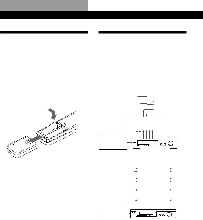
Insert two size AA (R6) batteries with the + and – on the battery compartment. When using the remote, point it at the remote sensor gon the processor.
|
] |
|
} |
} |
|
] |
||
|
zWhen to replace batteries
Under normal use, the batteries should last for about 6 months. When the remote no longer operates the processor, replace both batteries with new ones.
Notes
•Do not leave the remote in an extremely hot or humid place.
•Do not use a new battery with an old one.
•Do not expose the remote sensor to direct sunlight or lighting apparatuses. Doing so may cause a malfunction.
•If you don’t use the remote for an extended period of time, remove the batteries to avoid possible damage from battery leakage and corrosion.
Hooking Up the System
The surround processor allows you to connect up to 5 digital audio (video) source components, such as a DVD player or LD player with an AC-3 RF output. The illustration at right describes how to make connections between your digital audio (video) source components the surround processor, and your multichannel amplifier.
• Connecting an amplifier with 5.1 ch inputs
 Front speakers
Rear speakers
Centre speaker
 Subwoofer
MPEG or Dolby Digital (AC-3)
compatible amp (TA-VA8ES, etc.)
DVD player,
LD player, etc.
• Connecting separate amplifiers for each speaker
Amplifier for |
|
|
Front |
|
|
||
Front Speakers |
|
|
Speakers |
|
|
||
|
|
|
|
|
|
|
|
Amplifier for |
|
|
Rear |
|
|||
Rear Speakers |
|
|
Speakers |
|
|
|
|
|
|
|
|
Amplifier for |
|
|
Centre |
Centre Speaker |
|
|
Speaker |
|
|
|
|
|
|
|
|
Amplifier for |
|
|
Sub |
Subwoofer |
|
|
woofer |
|
|
|
|
DVD player,
LD player, etc.
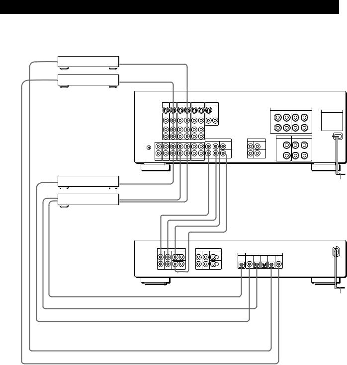
1Connect the OUTPUT terminals of the surround processor to the front (left and right), rear (left and right) centre and sub woofer channel inputs on your amplifier (for TA-VA8ES/TA-VA70, connect the to the 5.1 INPUT terminals as shown on the following page).
2Connect the digital audio outputs of each component to the appropriate terminals on the back of the surround processor.
This unit’s digital inputs detect MPEG, Dolby Digital (AC-3) or PCM signals automatically. The AC-3 RF input terminal for use with LD players is for Dolby Digital (AC-3) signals only.
4GB
Getting Started
Connecting an amplifier with 5.1 ch inputs (such as the Sony TA-VA8ES/TA-VA70, etc.)
|
from AUDIO/ |
ç |
The arrow çindicates signal flow. |
DVD player, etc.* |
VIDEO OUT |
||
|
from AUDIO/ |
|
|
LD player** |
VIDEO OUT |
ç |
|
|
|
|
|
|
|
|
|
|
|
|
TA-VA8ES/TA-VA70 |
|
|
TV |
LD |
VIDEO 2 |
VIDEO 1 |
MONITOR |
|
|
|||
|
|
IN |
IN |
OUT |
IN |
OUT |
IN |
OUT |
|
|
|
|
|
|
|
|
|
|
|
|
|
FRONT |
SPEAKERS |
|
|
|
|
|
|
|
|
|
|
|
SWITCHED AC OUTLETS |
|
|
VIDEO |
VIDEO |
VIDEO |
VIDEO |
VIDEO |
VIDEO |
|
|
|
|
|
|
IN |
IN |
OUT |
IN |
OUT |
IN |
OUT 2 |
OUT 1 |
|
|
|
|
AUDIO |
AUDIO |
AUDIO |
AUDIO |
AUDIO |
AUDIO |
|
|
|
|
|
|
IN |
IN |
OUT |
IN |
OUT |
IN |
|
|
|
|
|
|
|
|
|
|
|
|
|
|
CENTER SPEAKER |
REAR SPEAKERS |
|
|
|
|
|
|
|
|
|
5.1 INPUT |
SURROUND OUT |
|
|
y |
|
|
|
|
|
|
FRONT |
REAR CENTER |
REAR CENTER |
|
|
|
|
|
|
|
|
|
|
|
|
|
|
IN |
IN |
IN |
REC OUT |
IN |
REC OUT |
IN |
|
WOOFER |
WOOFER |
|
|
PHONO |
TUNER |
CD |
DAT/MD |
TAPE |
|
|
|
|
||
CD player, etc. |
from OUTPUT ç |
|
|
|
|
|
|
|
|
to mains |
|
|
|
|
|
|
|
|
|
|
|
|
|
to INPUT
DAT/MD deck
 from OUTPUT
ç
ç
ç
ç
ç
ç
SDP-EP90ES/EP70
|
OUTPUT |
|
|
BYPASS INPUT |
|
|
|
|
|
FRONT |
REAR |
CENTER |
FRONT |
REAR |
CENTER |
|
|
|
|
L |
L |
|
L |
L |
OUTPUT |
|
INPUT |
|
|
|
|
|
|
|
|
|
|
||
|
|
|
|
|
DIGITAL DIGITAL |
DIGITAL |
DIGITAL |
DIGITAL |
AC-3 |
|
|
|
|
|
4 |
3 |
2 |
1 |
RF |
R |
R |
WOOFER |
R |
R |
WOOFER |
|
|
|
|
to OPTICAL DIGITAL INPUT ç
to mains
from OPTICAL DIGITAL OUTPUT ç from COAXIAL DIGITAL OUTPUT ç
from OPTICAL DIGITAL OUTPUT* ç from AC-3 RF OUTPUT ç
Notes on connection
•Do not connect the mains lead to a mains or press the U(POWER) switch before completing all connections.
•The cable connectors should be fully inserted into the jacks. Loose connection may cause hum and noise.
•Jacks and plugs of the connecting cords are colorcoded as follows:
Yellow jacks and plugs: Video signal Red jacks and plugs: Right audio channel White jacks and plugs: Left audio channel
You can use either red or white cables to connect the centre speaker and sub woofer.
*If your DVD player has a COAXIAL DIGITAL OUTPUT, we recommend connecting the DVD player’s COAXIAL DIGITAL INPUT to the this unit’s DIGITAL INPUT 4 (COAXIAL IN) instead of making the optical connection shown above.
**If your LD player has an optical digital output, connect it to one of the DIGITAL INPUT 1~3 jacks on this unit. This connection can be used together with the AC-3 RF connection.
(continued)
5GB

Getting Started
zIf you have an additional surround amplifier with pre out terminals (such as the Sony TA-E2000ESD)
You can connect it to this unit’s BYPASS INPUT jacks. The signals from the connected amplifier will be output without alteration from this unit’s OUTPUT jacks when you select BYPASS (see page 11 for details).
zIf you have an additional centre speaker or active sub woofer
Connect the other CENTER OUTPUT terminal to the input on the amplifier for your other centre speaker. Connect the other WOOFER OUTPUT terminal to the input terminal on the active woofer.
|
|
|
|
|
Amplifier for |
TA-VA8ES |
SDP-EP90ES/EP70 |
centre speaker |
|||
5.1 INPUT |
|
|
OUTPUT |
|
INPUT |
FRONT REAR |
CENTER |
FRONT |
REAR |
CENTER |
ç |
|
|
L |
L |
|
|
|
WOOFER |
|
|
|
|
|
|
ÇÇ R |
|
|
INPUT |
|
|
R |
WOOFER |
ç |
|
|
|
Ç |
|
|
|
|
|
Ç |
|
|
Active Woofer |
Connecting digital components
You can connect the digital output jacks of a DVD player, DAT/MD deck, CD player (etc.) to the surround processor’s digital input jacks (DIGITAL INPUT 1~4).
You can also connect the AC-3 RF output terminal of an LD player to the surround processor’s AC-3 RF INPUT terminal.
You can connect the surround processor’s digital output jack (DIGITAL OUTPUT) to a DAT/MD deck.
What cords will I need?
•Optical digital connecting cord (not supplied)
•Coaxial digital connecting cord (not supplied)
Hookups
The arrow çindicates signal flow.
DVD player
Be sure to connect the DVD player’s digital output to one of the surround processor’s DIGITAL INPUT 1~4 jacks.
DVD player |
Surround processor |
|
|||
DIGITAL |
OUTPUT |
|
INPUT |
|
|
|
DIGITAL DIGITAL |
DIGITAL |
DIGITAL |
DIGITAL |
AC-3 |
|
4 |
3 |
2 |
1 |
RF |
OUT |
|
|
|
|
|
If your DVD player has a COAXIAL DIGITAL OUTPUT, we recommend connecting the DVD player’s COAXIAL DIGITAL INPUT to the this unit’s DIGITAL INPUT 4 (COAXIAL IN) instead of making the optical connection shown above.
LD player
Be sure to connect the LD player’s AC-3 RF output to the surround processor’s AC-3 RF INPUT jacks.
LD player |
|
Surround processor |
|
|||
AC-3 |
OUTPUT |
|
|
INPUT |
|
|
RF |
DIGITAL |
DIGITAL |
DIGITAL |
DIGITAL |
DIGITAL |
AC-3 |
|
||||||
|
|
4 |
3 |
2 |
1 |
RF |
OUT |
|
|
|
|
|
|
If your LD player has an optical digital output, connect it to one of the DIGITAL INPUT 1~3 jacks on this unit.
This connection can be used together with the AC-3 RF connection.
CD player
CD player |
|
Surround processor |
|
|||
DIGITAL |
OUTPUT |
|
|
INPUT |
|
|
|
DIGITAL |
DIGITAL |
DIGITAL |
DIGITAL |
DIGITAL |
AC-3 |
|
|
4 |
3 |
2 |
1 |
RF |
OUT |
|
|
|
|
|
|
DAT/MD deck
DAT/MD deck |
|
Surround processor |
|
|||
DIGITAL |
OUTPUT |
|
|
INPUT |
|
|
|
DIGITAL |
DIGITAL |
DIGITAL |
DIGITAL |
DIGITAL |
AC-3 |
|
|
4 |
3 |
2 |
1 |
RF |
IN OUT |
|
|
|
|
|
|
Note
This unit is only compatible with digital components using 32 kHz/44.1 kHz/48 kHz sampling frequencies. It is not compatible with 96 kHz.
6GB
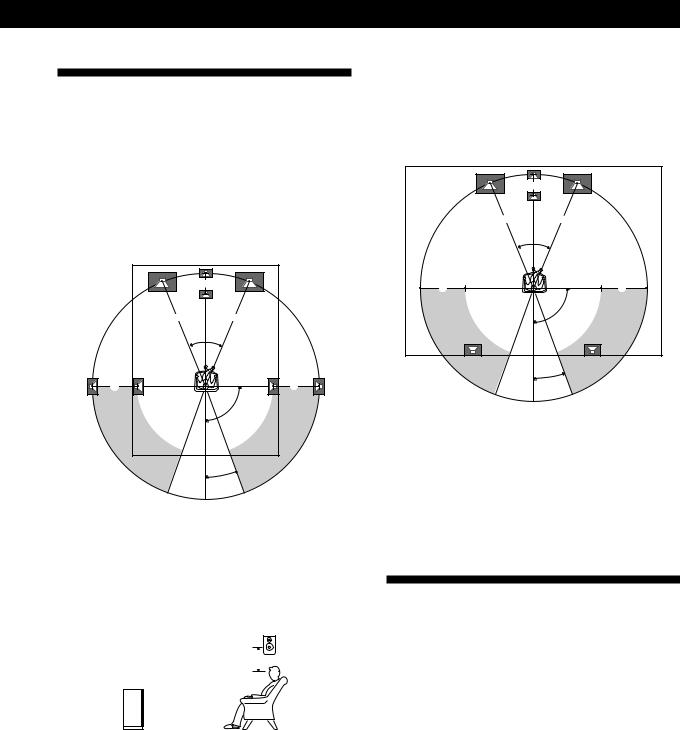
Speaker Placement
For the best possible surround sound all speakers should be the same distance from the listening position (A).
(However, this unit lets you to place the centre speaker up to 1.5 metres closer (B) and the rear speakers up to 4.5 metres closer (C) to the listening position.
The front speakers can be placed from 1.0 to 12.0 metres from the listening position (A).)
B |
AA
45°
C |
C |
90°
20°
Notes
•Do not place the centre or rear speakers farther away from the listening position than the front speakers.
•When mounting the rear speakers on side walls perpendicular to the listening position they should be placed 60 - 90 cm above the listening position.
Rear speaker
60 - 90 cm 

Front speaker
Getting Started
Depending on the shape of your room (etc.), you may wish to place the rear speakers behind you instead of on the side walls. One advantage of this placement is that you can use a pair of large floor standing speakers matching your front speakers.
B |
AA
45°
C |
C |
90°
20°
Note
If you place the rear speakers behind you, be sure to check the speaker location setting in the SP. SETUP menu when using VIRTUAL MULTI REAR and VIRTUAL REAR SHIFT sound fields (see pages 8 and 13 for details).
Before You Use Your Processor
Before you start using your processor, make sure that you have:
•Turned MASTER VOLUME to –20 dB (near the centre position).
Turn on the processor and check the following indicator.
•Press MUTING on the remote if “MUTING ON” appears in the display.
•Press BYPASS or one of the INPUT buttons if “BYPASS ON” appears in the display.
•Press SET UP to register the type of speakers you have connected and their distance from your listening position (see “Speaker Set Up” on the following page).
7GB
Getting Started
Speaker Set Up
To obtain the best possible surround sound, first specify the type of speakers you have connected and their distance from your listening position. Then use the test tone to adjust the speaker volumes to the same level.
Specifying the speaker type and distance
|
|
|
U |
|
|
|
|
|
|
|
|
|
|
|
|
|
|
|
|
|
|
|
|
|
SET UP |
|||||||||||||
|
|
|
|
|
|
|
|
|
|
|
|
|
|
|
|
|
|
|
|
|
|
|
|
|
|
|
|
|
|
|
|
|
|
|
|
|
|
|
|
|
|
|
|
|
|
|
|
|
|
|
|
|
|
|
|
|
|
|
|
|
|
|
|
|
|
|
|
|
|
|
|
|
|
|
|
|
|
|
|
|
|
|
|
|
|
|
|
|
|
|
|
|
|
|
|
|
|
|
|
|
|
|
|
|
|
|
|
|
|
|
|
|
|
|
|
|
|
|
|
|
|
|
|
|
|
|
|
|
|
|
|
|
|
|
|
|
|
|
|
|
|
|
|
|
|
|
|
|
|
|
|
|
|
|
|
|
|
|
|
|
|
|
|
|
|
|
|
|
|
|
|
|
|
|
|
|
|
|
|
|
|
|
|
|
|
|
|
|
|
|
|
|
|
|
|
|
|
|
|
|
|
|
|
|
|
|
|
|
|
|
|
|
|
|
|
|
|
|
|
|
|
|
|
|
|
|
|
|
|
|
|
|
|
+/–
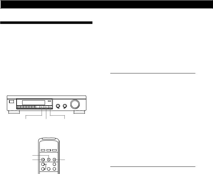
1Press U(POWER) on the front panel to turn on the processor.
2Press SET UP.
“SP.SETUP” appears in the display
3Press SET UP repeatedly to select the parameter you want to adjust.
4Turn the +/– knob to select the setting you desire. The settings is entered automatically.
5Repeat steps 3 and 4 until you have set all of the parameters shown below.
6Press SET UP to exit the set up mode.
Front speaker size
Initial setting is : FRONT SP [LARGE]
•If you connect large speakers that will effectively reproduce bass frequencies, select “LARGE”.
•If you connect small speakers with minimal bass response, select “SMALL” to activate the Dolby Digital (AC-3) bass redirection circuitry and output the front channel bass frequencies from the sub woofer or other “LARGE” speakers.
Centre speaker size
Initial setting is : CENTER SP [LARGE]
•If you connect large speakers that will effectively reproduce bass frequencies, select “LARGE” (WIDE mode).
•If you connect small speakers with minimal bass response, select “SMALL” to activate the Dolby Digital (AC-3) bass redirection circuitry and output the centre channel bass frequencies from the front speakers, sub woofer or other “LARGE” speakers (NORMAL mode).
•If you do not connect the centre speaker, select “NO” (PHANTOM mode).
Rear speaker size
Initial setting is : REAR SP [LARGE]
•If you connect large speakers that will effectively reproduce bass frequencies, select “LARGE”.
•If you connect small speakers with minimal bass response, select “SMALL” to activate the Dolby Digital (AC-3) bass redirection circuitry and output the rear channel bass frequencies from the sub woofer or other “LARGE” speakers.
•If you do not connect rear speakers, select “NO” (3 CH mode).
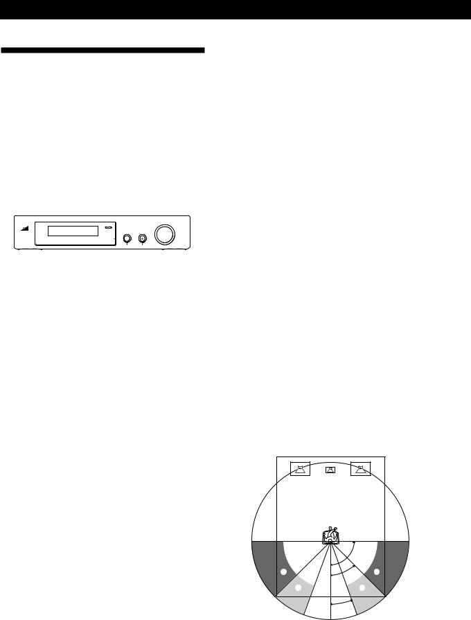
Rear speaker position
Initial setting is : REAR SP [ SIDE ]
This parameter lets you specify the location of your rear speakers for proper implementation of the Digital Cinema Sound VIRTUAL REAR SHIFT and VIRTUAL MULTI REAR modes. Refer to the illustration below.
•Set to SIDE if the location of your rear speakers corresponds to section A.
•Set to BEHIND if the location of your rear speakers
corresponds to section B.
This setting effects only the VIRTUAL REAR SHIFT and VIRTUAL MULTI REAR modes.
|
90° |
A |
A |
|
45° |
B |
B |
|
20° |
8GB
Sub woofer selection
Initial setting is : SUB WOOFER [YES]
•If you connect a sub woofer, select “YES” to output the LFE (low frequency effect) channel from the sub woofer.
•If you do not connect a sub woofer, select “NO”. This activates the MPEG/Dolby Digital (AC-3) bass redirection circuitry and outputs the LFE signals from other speakers.
•In order to take full advantage of the Dolby Digital (AC-3) bass redirection circuitry, we recommend setting the sub woofer’s cut off frequency as high as possible. (However, when using an amplifier with 5.1 ch inputs, set the sub woofer’s cut off frequency to match the characteristics of the amplifier.
Front speaker distance
Initial setting is : FRONT 5.0 meter
Set the distance from your listening position to the front (left or right) speaker (A on page 7).
•Front speaker distance can be set in 0.1 metre steps from 1.0 to 12.0 metres.
•If both speakers are not placed an equal distance from your listening position, set the distance to the closest speaker.
Centre speaker distance
Initial setting is : CENTER 5.0 meter
Set the distance from your listening position to the centre speaker.
•Centre speaker distance can be set in 0.1 metre steps from a distance equal to the front speaker distance (A on page 7) to a distance 1.5 metres closer to your listening position (B on page 7).
•Do not place the centre speaker farther away from your listening position than the front speakers.
Rear speaker distance
Initial setting is : REAR 3.5 meter
Set the distance from your listening position to the rear (left or right) speaker.
•Rear speaker distance can be set in 0.1 metre steps from a distance equal to the front speaker distance (A on page 7) to a distance 4.5 metres closer to your listening position (C on page 7).
•Do not place the rear speakers farther away from your listening position than the front speakers.
•If both speakers are not placed an equal distance from your listening position, set the distance to the closest speaker.
zTo manually adjust the bass roll off frequency for each channel
When the front, centre, or rear speaker sizes are set to small, the bass roll off frequency is automatically set to 120 Hz. To select a different roll off frequency, set the menu mode to EXPAND and use the front, centre, or rear speaker roll off parameters in the speaker set up menu.
For details about the menu mode, see page 15.
For details about the roll off parameters, see page 19.
Getting Started
Adjusting the speaker volume
Use the remote while seated in your listening position to adjust the volume of each speaker.
2 A

 1, 3
1, 3
2 B 

 2 C
2 C 


 2 D
2 D 

 MASTER
VOLUME
Note
This unit incorporates a new test tone with a frequency centred at 800 Hz for easier speaker volume adjustment.
1Press TEST.
You will hear the test tone from each speaker in sequence.
2From your listening position, use the remote to adjust the volume of each speaker so that the test tone can be heard at the same level from all speakers.
APress FRONT BAL L or R to adjust the balance between the front left and right speakers (±8 dB, 0.5 dB/steps).
During this adjustment, the test tone is emitted from both speakers simultaneously.
BPress REAR BAL L or R to adjust the balance between the rear left and right speakers (±8 dB, 0.5 dB/steps).
During this adjustment, the test tone is emitted from both speakers simultaneously.
CPress CENTER + or – to adjust the level of centre speaker (0.5 dB/steps).
During this adjustment, the test tone is emitted from the centre speaker.
DPress REAR + or – to adjust the level of rear speakers (0.5 dB/steps).
During this adjustment, the test tone is emitted from both speakers simultaneously.
3 Press TEST to turn off the test tone.
(continued)
9GB

Getting Started
zTo adjust the volume of all the speakers at one time
Use MASTER VOLUME on the processor, remote, or your multichannel processor.
When using an amplifier with 5.1 ch inputs, set this unit’s MASTER VOLUME to –20 dB (near the centre position) and adjust the amplifier’s volume control.
zTo set the test tone to a specific channel
Set the menu mode to EXPAND and use the test tone parameter in the LEVEL ADJUST menu to select the channel you desire.
For details about the menu mode, see page 15.
For details about the test tone parameter, see page 15.
Notes
•The front balance, rear balance, centre level, and rear level are shown in the display during adjustment.
•Although these adjustments can also be made with the LEVEL ADJUST menu using the knobs on the front panel, we recommend you follow the procedure described above and adjust the speaker levels from your listening position using the remote control.
10GB
|
|
|
|
Processor Operations |
Processor Operations |
|
|
|
Selecting a Component
To listen to or watch a connected component, first select the function on the processor or with the remote. Before you begin, make sure you have:
•Connected all components securely and correctly as indicated on pages 4 to 7.
•Turned MASTER VOLUME to –20 dB (near the centre position) (when using an amplifier with 5.1 ch inputs).
•Turned MASTER VOLUME to –∞ dB (when using separate amplifiers for each speaker).
|
|
|
U |
|
|
|
INPUT buttons |
|
MASTER VOLUME |
|||||||||||||||||
|
|
|
|
|
|
|
|
|
|
|
|
|
|
|
|
|
|
|
|
|
|
|
|
|
|
|
|
|
|
|
|
|
|
|
|
|
|
|
|
|
|
|
|
|
|
|
|
|
|
|
|
|
|
|
|
|
|
|
|
|
|
|
|
|
|
|
|
|
|
|
|
|
|
|
|
|
|
|
|
|
|
|
|
|
|
|
|
|
|
|
|
|
|
|
|
|
|
|
|
|
|
|
|
|
|
|
|
|
|
|
|
|
|
|
|
|
|
|
|
|
|
|
|
|
|
|
|
|
|
|
|
|
|
|
|
|
|
|
|
|
|
|
|
|
|
|
|
|
|
|
|
|
|
|
|
|
|
|
|
|
|
1 Press U(POWER) to turn on the processor.
3When connected to an amplifier with 5.1 ch inputs, turn on your amplifier, select the respective component, then select the 5.1 channel input.
EXAMPLE: Turn FUNCTION to select “LD”, then press 5.1 INPUT (for Sony TA-VA8ES). At this time, set the MASTER VOLUME control on your amplifier to “0”.
4Turn on the source component, the LD player for example, and start playback.
5Use the MASTER VOLUME on your amplifier to adjust the volume.
To |
Do this |
|
|
Mute the sound |
Press MUTING on the remote. |
|
Press again to restore the sound |
|
|
Reinforce the bass |
Press BASS BOOST to turn on the |
|
B.BOOST indicator. |
|
|
Turn off the display |
Press DISPLAY on the remote. |
|
|
Adjust the level of the |
Press the SUB WOOFER +/– on |
sub woofer* |
the remote. |
2Press an INPUT button to select the component you want to use:
To listen to or watch |
Press |
|
|
An LD player connected to the |
AC-3 RF |
AC-3 RF INPUT jack |
|
|
|
The component connected to the |
DIGITAL 1, 2, or 3 |
DIGITAL 1, 2, or 3 optical input |
|
jack.* |
|
|
|
The component connected to the |
DIGITAL 4 |
DIGITAL 4 coaxial input jack. |
|
|
|
The component connected to the |
BYPASS** |
BYPASS input jacks. |
|
*This unit’s digital inputs detect MPEG, Dolby Digital (AC-3), or PCM signals automatically. (The AC-3 RF input terminal for use with LD players is for Dolby Digital (AC-3) signals only.)
**• The menu functions may not be available when the unit is set to the “BYPASS ON” mode.
•If you connected an additional audio amplifier (etc.) to the BYPASS IN jacks on the processor as described on page 6, use the function selector on that component to select the component you want to listen to (“CD” for example).
•This unit switches to the “BYPASS ON” mode while its POWER is set to off.
*In order to take full advantage of the MPEG/Dolby Digital (AC-3) bass redirection circuitry, we recommend setting the sub woofer’s cut off frequency as high as possible. (However, when using an amplifier with 5.1 ch inputs, set the sub woofer’s cut off frequency to match the characteristics of the amplifier.)
Using the remote Z
The remote lets you operate the processor.
EXAMPLE: To listen to a Dolby Digital (AC-3) encoded Laserdisc played back in
INPUT SELECT </> 


 BYPASS
1Press U(POWER) on the front panel to turn on the processor.
2Press INPUT SELECT < or > repeatedly to display the input for the component you want to use (or press BYPASS to display “BYPASS ON”).
EXAMPLE: If you connected your LD player to the AC-3 RF INPUT, select “AC-3 RF”.
11GB
Processor Operations
z When you select DOLBY SURROUND
Selecting a Surround Field
You can select a surround field according to the type of source you are playing.
When playing programme sources recorded in the MPEG or Dolby Digital (AC-3) format, you can enjoy surround sound simply by selecting “MPEG/DOLBY DIGITAL”.
This unit also incorporates several pre-programmed sound modes called “Digital Cinema Sound”. Select from these surround modes according to your preference to enjoy powerful surround effects from a wide variety of programme sources.
MPEG/DOLBY DIGITAL MODE |
OFF |
MODE |
|
MPEG/DOLBY |
OFF |
DIGITAL |
|
When the signal being input is PCM, normal 2 channel playback occurs.
When the signal being input is Dolby Digital (AC-3), the number of channels played back are determined automatically according to the characteristics of the input signal.
In the “DOLBY SURROUND” mode the number of channels being played back from the current programme source appear in the display as shown below:
Display |
Channels played back |
|
|
STEREO PCM [xx kHz]* |
Normal PCM playback |
MPEG AUDIO [1/0]** |
Centre only (mono) |
DOLBY DIGITAL [1/0]** |
|
MPEG AUDIO [2/0] |
Front (L, R) |
DOLBY DIGITAL [2/0] |
|
MPEG AUDIO [2/1] |
Front (L, R) + Rear (mono) |
DOLBY DIGITAL [2/1] |
|
MPEG AUDIO [2/2] |
Front (L, R) + Rear (L, R) |
DOLBY DIGITAL [2/2] |
|
MPEG AUDIO [3/0]** |
Front (L, R) + Centre |
DOLBY DIGITAL [3/0]** |
|
MPEG AUDIO [3/1] |
Front (L, R) + Centre + |
DOLBY DIGITAL [3/1] |
Rear (mono) |
MPEG AUDIO [3/2] |
Front (L, R) + Centre + |
DOLBY DIGITAL [3/2] |
Rear (L, R) |
DOLBY PROLOGIC |
Front (L, R) + Centre + |
|
Rear (mono) |
*48 kHz, 44.1 kHz, or 32 kHz is displayed. 44.1 kHz is displayed as “44 kHz”.
**The surround effect may not be readily apparent in all cases.
To select the MPEG or Dolby Digital surround modes
Press MPEG/DOLBY DIGITAL.
Normally, select this mode when playing programme sources recorded in the MPEG or Dolby Digital (AC-3) format.
To select Digital Cinema Sound
Press MODE repeatedly until the mode you desire appears in the display.
See the chart on the following page for details regarding the types of surround modes available and the effects they provide.
When playing a 2 channel MPEG or Dolby Digital (AC- 3) source, the unit determines either Pro Logic of stereo playback automatically according to the information provided by the programme source.
zYou can find Dolby Surround-encoded software by looking at the packaging
Use discs with the 


 logo. In order to enjoy Dolby Digital (AC-3) playback you must use discs bearing this logo.
12GB
Processor Operations
Digital Cinema Sound |
Ill.1 VIRTUAL ENHANCED (SURROUND) A |
|||
Surround |
Effect |
L |
C |
R |
|
|
|
||
mode |
|
|
|
|
NORMAL |
Decodes programmes processed with |
|
|
|
SURROUND |
MPEG or Dolby Surround. Use to decode 2 |
|
|
|
|
ch sources using Dolby Pro Logic |
|
|
|
|
decoding. |
|
|
|
ENHANCED |
Provides a greater sense of presence from |
SURROUND |
Pro Logic sources with monaural rear |
|
channel sound. Produces a stereo like |
|
effect in the rear channels. |
|
|
LARGE |
Reproduces the acoustics of a standard |
THEATER |
movie theatre. |
|
|
CINEMA |
Reproduces the sound characteristics of |
STUDIO A |
the Sony Pictures Entertainment “Cary |
|
Grant Theatre” cinema production studio. |
|
|
CINEMA |
Reproduces the sound characteristics of |
STUDIO B |
the Sony Pictures Entertainment “Kim |
|
Novak Theatre” cinema production studio. |
|
|
CINEMA |
Reproduces the sound characteristics of |
STUDIO C |
the Sony Pictures Entertainment scoring |
|
stage. |
|
|
VIRTUAL |
Uses 3D sound imaging to create virtual |
ENHANCED |
rear speakers from the sound of the front |
(SURROUND) |
speakers without using actual rear |
A (Ill.1) |
speakers. |
|
The virtual speakers are reproduced as |
|
shown in Ill. 1. |
|
|
VIRTUAL |
Uses 3D sound imaging to create virtual |
ENHANCED |
rear speakers from the sound of the front |
(SURROUND) |
speakers without using actual rear |
B (Ill.2) |
speakers. |
|
The virtual speakers are reproduced as |
|
shown in Ill. 2. |
|
|
VIRTUAL |
Uses 3D sound imaging to shift the sound |
REAR |
of the rear speakers away from the actual |
SHIFT |
speaker position. The shift position differs |
(Ill.3) |
according to the setting of the rear speaker |
|
position (SP. SETUP). |
|
|
VIRTUAL |
Uses 3D sound imaging to create an array |
MULTI |
of virtual rear speakers from a single pair |
REAR |
of actual rear speakers. The position of the |
(Ill.4) |
virtual rear speakers differs according to |
|
the setting of the rear speaker position (SP. |
|
SETUP). |
|
|
LARGE |
Reproduces the acoustics of a live house. |
HALL |
Use when playing recordings of live |
|
concerts (etc.). |
|
|
LIVE |
Creates a simulated surround sound from |
HOUSE |
monaural sources such as old movies or |
|
TV programmes. |
|
|
To turn off the surround effect (2 channel stereo playback)
Press OFF (or DIGITAL CINEMA SOUND - OFF on the remote). At this time MPEG or Dolby Digital (AC-3) signals are automatically downmixed to front (L, R) signals.
Ill.2 VIRTUAL ENHANCED (SURROUND) B
L C R
|
|
|
|
|
|
|
|
|
|
|
|
|
|
|
|
|
|
Ill.3 VIRTUAL REAR SHIFT |
|
|
|
|
|
|
|
|
|||||||||
|
For REAR SP [SIDE]* |
For REAR SP [BEHIND]* |
|||||||||||||||
|
L |
C |
|
R |
|
|
L |
C |
|
R |
|||||||
|
|
|
|
|
|
|
|
|
|
|
|
|
|
|
|
|
|
SL |
SR |
SL SR
Ill.4 VIRTUAL MULTI REAR |
|
|
|
|
|
|
|
||||||
|
For REAR SP [SIDE]* |
For REAR SP [BEHIND]* |
|||||||||||
|
L |
C |
|
R |
|
L |
C |
|
R |
||||
|
|
|
|
|
|
|
|
|
|
|
|
|
|
SL |
SR |
|
SL |
SR |
L : Front speaker (left) |
* See page 8 for details on |
|
R : Front speaker (right) |
how to set the rear speaker |
|
C : Centre speaker |
position. |
|
SL : Rear speaker (left) |
|
|
SR : Rear speaker (right) 
 : Virtual speaker
(continued)
13GB

Processor Operations
Adjusting the Surround Effect Level (for Digital Cinema Sound modes only*)
You can adjust the surround effect level. This control lets you adjust the “presence” of the current Digital Cinema Sound mode from 0% (no digital cinema sound effects) to 100% (150%) in 5% steps.
*This adjustment is not possible in the NORMAL SURROUND or ENHANCED SURROUND mode.
1Start playing a programme source.
2Press DIGITAL CINEMA SOUND - MODE on the remote repeatedly to select the mode you desire.
3Press EFFECT + or – on the remote to select the level you prefer. The effect level is indicated in the display during adjustment. The level is stored automatically.
Note
Changing the effect level may not produce major variations in the surround effect when used with certain playback sources.
zYou can also adjust the surround effect level using the controls on the front panel.
Use the MENU and the +/– knobs to adjust the surround effect level parameter in the SURROUND menu.
See page 15 for details on menu operations and the surround effect level parameter.
Compressing the dynamic range (MPEG or Dolby Digital (AC-3) only)
When inputting a MPEG or Dolby Digital (AC-3) signal you can compress the dynamic range of the sound track by using the dynamic range compression parameters in the SURROUND menu. This may be useful when you want to watch movies at low volumes late at night. See page 15 for details on menu operations and page 16 for details on the dynamic range compression parameter.
Digital Recording
This processor makes it easy to make digital recordings from the components connected to the processor. You don’t have to connect playback and recording components directly.
Before you begin, make sure you’ve connected all components properly.
INPUT buttons
|
|
ç |
|
|
|
ç |
|
|
|
|
|
|
|
|
|
||
|
|
|
|
|
|
|
||
|
Playback component |
|
Digital recording |
|
||||
|
(CD player, etc.) |
|
component |
|
||||
|
|
|
|
|
(DAT deck, MD |
|
||
|
|
|
|
|||||
ç: Signal flow |
|
deck , etc.) |
|
|||||
EXAMPLE: Recording a CD using a DAT deck
See your DAT or CD player’s instruction manual if you need help.
1Press DIGITAL 1 (if a CD player is connected to the DIGITAL 1 INPUT) to select the CD player.
2Insert a blank digital audio tape into the DAT for recording.
3Start recording on the DAT and then start playing the CD you want to record.
Note
You cannot record the digital signal from a MPEG or Dolby Digital (AC-3) programme source.
14GB
Processor Operations
Settings and Adjustments
The menu operations allow you to customize various aspects of the processor to suit your listening environment, your speakers, your components, and your personal preferences.
You can select between two menu modes (basic and expand) according to your needs.
•The basic menu mode (BASIC) lets you make general adjustments to the sound fields and adjust all speaker settings simultaneously.
•The expanded menu mode (EXPAND) lets you make precise individual adjustments to the equalization and low cut frequency of the front, centre, and rear speakers, and determine the default settings for the digital inputs.
Note
If you switch from EXPAND mode to BASIC mode, the adjustments made in the EXPAND mode are retained. However, if you adjust parameters from the same menu in the BASIC mode, those settings change accordingly.
For example, when you switch to the basic mode, the individual tone controls for each speaker (in the EQUALIZER menu) are preserved. However, a single adjustment to the general tone controls (in the SURROUND menu) sets all speaker equalizations to the front speaker settings.
MENU +/–
1Push the MENU knob repeatedly to display one of the following menus:
BASIC mode |
EXPAND mode |
LEVEL ADJUST menu |
LEVEL ADJUST menu |
SURROUND menu |
SURROUND menu |
SP. SETUP menu |
EQUALIZER menu |
CUSTOMIZE menu |
SP. SETUP menu |
|
CUSTOMIZE menu |
2Turn the MENU knob to select the parameter you desire from the respective menu.
3Turn the +/– knob to select the setting you desire. The setting is entered automatically.
4Repeat steps 1 through 3 to make all necessary adjustments.
When using the controls on the remote
1Press SELECT repeatedly to display the desired menu.
2 Press MENU </< repeatedly to select the parameter you desire from the respective menu
3Press +/– repeatedly to select the setting you desire. The setting is entered automatically.
4Repeat steps 1 through 3 to make all necessary adjustments.
Note
Certain menu items may not be available for adjustment depending on the current settings and menu modes. Unavailable items appear dimmed when shown in the display.
LEVEL ADJUST menu
The LEVEL ADJUST menu contains speaker level adjustment parameters that allow you to balance output level to each speaker.
zMost of these settings can also be adjusted directly using remote. See “Adjusting the speaker volume” (page 9).
Test tone
Initial setting is : TEST TONE OFF
Lets you turn the test tone on and off.
•When the menu mode is set to BASIC, you can select between “OFF” and “[ ] auto”. “[ ] auto” provides the same test tone activity as the described on page 8.
•When the menu mode is set to EXPAND, you can select which speaker will emit the test tone; [L]: left (front), [C]: centre, [R]: right (front), [SR]: rear right, [SL]: rear left.
Front speaker balance
Initial setting is : FRONT L ___1___ R
Lets you adjust the balance between the front left and right speakers.
• The balance can be adjusted ±8.0 dB in 0.5 dB steps.
Rear speaker balance
Initial setting is : REAR L ___1___ R
Lets you adjust the balance between the rear left and right speakers.
• The balance can be adjusted ±8.0 dB in 0.5 dB steps.
Rear speaker level
Initial setting is : REAR LEVEL 0 dB
Lets you adjust level of the rear (left and right) speakers.
•The level can be adjusted in 0.5 dB steps from –20.0 dB to +10.0 dB.
•Selecting MUTE completely mutes the sound (–∞) from the rear speakers. In this case, the sound of the rear channels is not output from the front speakers, etc.
(continued)
15GB

Processor Operations
Centre speaker level
Initial setting is : CENT.LEVEL 0 dB
Lets you adjust the level of the centre speaker.
•The level can be adjusted in 0.5 dB steps from –20.0 dB to +10.0 dB.
•Selecting MUTE completely mutes the sound (–∞) from the centre speaker. In this case, the sound of the centre channel is not output from the front speakers, etc.
Sub woofer level
Initial setting is : SUB WOOFER 0 dB
Lets you adjust the level of the sub woofer.
•The level can be adjusted in 0.5 dB steps from –20.0 dB to +10.0 dB.
•Selecting MUTE mutes the sound from the sub woofer.
SURROUND menu
The SURROUND menu contains parameters that let you customize various aspects of the current surround field. The settings available in this menu are stored separately for each surround field. The parameter types vary according to the menu mode.
Surround effect level (Digital Cinema Sound modes only)
Initial setting is : SURR.EFFECT 100%
This parameter can be adjusted directly using EFFECT +/– on the remote. It lets you adjust the “presence” of the current digital cinema sound surround effect.
•The effect level can be adjusted from 0% (no digital cinema sound effects) to 100% (150%) in 5% steps.
Low Frequency Effect (LFE) mix level (DISCRETE only)
Initial setting is : LFE MIX. 0dB
This parameter lets you attenuate the level of the LFE (Low Frequency Effect) channel output from the sub woofer without effecting the level of the bass frequencies sent to the sub woofer from the front, centre or rear channels via the bass redirection circuitry.
•The level can be adjusted in 0.5 dB steps from –20.0 dB to 0 dB (line level). 0 dB outputs the full LFE signal at the mix level determined by the recording engineer.
•Selecting MUTE mutes the sound of the LFE channel from the sub woofer. However, the low frequency sounds of the front, centre, or rear speakers are output from the sub woofer according to the settings made for each speaker in the speaker setup (page 8).
Dynamic range compression ratio
Initial setting is : D.RANGE COMP OFF
Lets you compress the dynamic range of the sound track. This may be useful when you want to watch movies at low volumes late at night.
•OFF reproduces the sound track with no compression.
•STD reproduces the sound track with the full dynamic range as intended by the recording engineer.
•0.1 ~ 0.9 allow you to compress the dynamic range in small steps to achieve the sound you desire.
•MAX provides a dramatic compression of the dynamic range.
•During playback of MPEG sources, the compression radio is fixed (STD, 0.1 ~ 0.9, and MAX all produce the same effect).
Tone Control (on/off) •Basic mode only•
Initial setting is : TONE CONTROL OFF
Lets you turn the BASS and TREBLE tone control adjustments ON or OFF. You can use this setting to compare the sound of the BASS and TREBLE adjustments with that of the original signal.
•OFF flattens the frequency characteristics of all channels simultaneously. If you adjust the bass or treble levels after setting the tone control to OFF, the sound quality changes from the flat (0 dB) position.
•ON restores the frequency characteristics to the values present before the tone control was set to OFF.
Bass level adjustment •Basic mode only•
Initial setting is : BASS 0 dB
Lets you adjust the level of the bass frequencies of the front (left and right), centre, and rear (left and right) channels simultaneously. To adjust the LFE channel, see “Low Frequency Extension (LFE) mix level”.
•The level can be adjusted ±10 dB in 1 dB steps.
•The “0dB” setting represents line level (0 dB).
Treble level adjustment •Basic mode only•
Initial setting is : TREBLE 0 dB
Lets you adjust the level of the treble frequencies of the front (left and right), centre, and rear (left and right) channels simultaneously.
•The level can be adjusted ±10 dB in 1 dB steps.
•The “0dB” setting represents line level (0 dB).
16GB

Processor Operations
EQUALIZER menu •Expand mode only•
In EXPAND mode, the settings in this menu replace the tone control settings of the SURROUND menu. This menu contains parameters that allow you to adjustment to the tone of the front (left and right), centre, and rear (left and right) speakers individually.
Rear speaker treble adjustment
Level : REAR TREBLE 0dB Frequency : REAR TREBLE 2.5kHz
Adjust as described in “Front speaker bass adjustment”.
• The level can be adjusted ±10 dB in 0.5 dB steps.
Equalizer (on/off)
Initial setting is : EQUALIZER ON
Lets you turn the equalizer adjustments ON or OFF. You can use this setting to compare the sound of the equalizer adjustments with that of the original signal.
•OFF flattens the frequency characteristics of all channels simultaneously. If you adjust the bass or treble levels after setting the equalizer to OFF, the sound quality changes from the flat (0 dB) position.
•ON restores the frequency characteristics to the values present before the equalizer was set to OFF.
Front speaker bass adjustment
Level : FRONT BASS 0dB Frequency : FRONT BASS 250Hz
Use the +/– knob to adjust the level, then turn the MENU knob to move select the frequency (Hz) and use the +/– knob to adjust the frequency. Repeat until you achieve the sound you desire.
• The level can be adjusted ±10 dB in 0.5 dB steps.
Front speaker treble adjustment
Level : FRONT TREBLE 0dB Frequency : FRONT TREBLE 2.5kHz
Adjust as described in “Front speaker bass adjustment”.
• The level can be adjusted ±10 dB in 0.5 dB steps.
Centre speaker bass adjustment
Level : CENTER BASS 0dB Frequency : CENTER BASS 250Hz
Adjust as described in “Front speaker bass adjustment”.
• The level can be adjusted ±10 dB in 0.5 dB steps.
Centre speaker treble adjustment
Level : CENTER TREBLE 0dB Frequency : CENTER TREBLE 2.5kHz
Adjust as described in “Front speaker bass adjustment”.
• The level can be adjusted ±10 dB in 0.5 dB steps.
CUSTOMIZE menu
The CUSTOMIZE menu allows you to customize various aspects of the this unit’s operation. The parameters available in this menu vary depending on the menu mode (BASIC/EXPAND).
Muting
Initial setting is : MUTING OFF
Lets you mute the sound (same as MUTING button on the remote).
•ON mutes the sound from all speakers.
•OFF restores the sound to the original volume.
Display dimmer control
Initial setting is : DISP. DIMMER 100%
Lets you adjust the brightness of the display window. It can be adjusted in 1% steps from 25 to 100%.
Distance unit •Expand mode only•
Initial setting is : DIST.UNIT [meter]
Lets you select either metres or feet as the unit of measure for setting distances. 1 foot corresponds to a 1 ms difference.
Equalizer memory •Expand mode only•
Initial setting is : EQ MEMORY [ON]
•ON allows you to set the equalizer independently for each surround mode.
•OFF allows you to use fix the equalizer to one setting for all surround modes.
Memory clear
Initial setting is : MEMORY CLEAR [NO]
To clear the memory, select [YES] and wait a few seconds. “Are you sure?” is displayed. If you select [YES] again and wait a few seconds, the unit clears all of the parameters and resets them to the factory presets “MEMORY CLEARED!” is displayed as confirmation.
(continued)
Rear speaker bass adjustment
Level : REAR BASS 0dB Frequency : REAR BASS 250Hz
Adjust as described in “Front speaker bass adjustment”.
• The level can be adjusted ±10 dB in 0.5 dB steps.
17GB

Processor Operations
Menu mode selection
Initial setting is : MENU MODE [BASIC]
Lets you choose between the basic or the expand menu mode:
•The basic menu mode (BASIC) lets you make general adjustments to the sound fields and adjust the tone of all the speakers simultaneously.
•The expanded menu mode (EXPAND) lets you make precise individual adjustments to the equalization and low cut frequency of the front, centre, and rear speakers, and determine the default settings for the digital inputs.
SP. SETUP menu
The speaker setup menu contains parameters that allow you to set the type and size of the speakers in your system. This information is essential for production of realistic surround sound. The settings available in this menu can also be accessed by pressing SET UP (see “Speaker Set Up” on page 8 for details).
Front speaker size
Initial setting is : FRONT SP [LARGE]
Note
If you switch from EXPAND mode to BASIC mode, the adjustments made in the EXPAND mode are retained. However, if you adjust parameters from the same menu in the BASIC mode, those settings change accordingly.
For example, when you switch to the basic mode, the individual tone controls for each speaker (in the EQUALIZER menu) are preserved. However, a single adjustment to the general tone controls (in the SURROUND menu) sets all speaker equalizations to the front speaker settings.
zEven if you plan on making individual adjustments using the EQUALIZER menu,
We recommend that you start by using the tone controls in the basic menu mode and then make further refinements by switching to the expand mode and using the equalizer.
Digital input trim adjustment •Expand mode only•
Initial setting is : INPUT TRIM 0dB
Different components often have a different line levels. In such cases you can adjust the line level at each of the digital inputs. Settings are stored independently for each input.
Digital input mode •Expand mode only•
Initial setting is : DECODE MODE [AUTO]
Lets you specify the type of signal to be input to the currently digital input jack (AC-3 RF or DIGITAL 1~4). Settings are stored independently for each input.
•AUTO : This unit automatically switches between MPEG, Dolby Digital (AC-3), and PCM.
•AC-3 : All input signals are treated as Dolby Digital (AC- 3) signals. If a MPEG or PCM signal is input to a jack set to AC-3, no sound will be heard.
•MPEG : All input signals are treated as MPEG signals. If a Dolby Digital (AC-3) or PCM signal is input to a jack set to MPEG, no sound will be heard.
See page 8.
Centre speaker size
Initial setting is : CENTER SP [LARGE] See page 8.
Rear speaker size
Initial setting is : REAR SP [LARGE] See page 8.
Rear speaker position
Initial setting is : REAR SP [SIDE] See page 8.
Sub woofer selection
Initial setting is : SUB WOOFER [ YES ] See page 8.
Front speaker distance
Initial setting is : FRONT 5.0 meter See page 8.
Centre speaker distance
Initial setting is : CENTER 5.0 meter See page 8.
Rear speaker distance
Initial setting is : REAR 3.5 meter See page 8.
18GB

Processor Operations
Front speaker roll off frequency •Expand mode only•
Initial setting is : FRONT SP > 120 Hz
This setting lets you select the roll off frequency for the low cut filter of the front (left and right) speakers.
•The bass frequencies lower than the cut off frequency are divided by the MPEG/Dolby Digital (AC-3) bass redirection circuitry and output from the sub woofer or other “LARGE” speakers. In order to prevent clipping, frequencies below the cut off frequency are not output from the front speakers.
Centre speaker roll off frequency •Expand mode only•
Initial setting is : CENTER SP > 120 Hz
This setting lets you select the roll off frequency for the low cut filter of the centre speaker.
•The bass frequencies lower than the cut off frequency are divided by the MPEG/Dolby Digital (AC-3) bass redirection circuitry and output from the sub woofer or other “LARGE” speakers. In order to prevent clipping, frequencies below the cut off frequency are not output from the centre speaker.
Rear speaker roll off frequency •Expand mode only•
Initial setting is : REAR SP > 120 Hz
This setting lets you select the roll off frequency for the low cut filter of the rear (left and right) speakers.
•The bass frequencies lower than the cut off frequency are divided by the MPEG/Dolby Digital (AC-3) bass redirection circuitry and output from the sub woofer or other “LARGE” speakers. In order to prevent clipping, frequencies below the cut off frequency are not output from the rear speakers.
19GB

Processor Operations
Understanding the Display
|
1 |
2 |
3 |
|
4 |
|
|
5 |
6 |
|
|
|
|
||||||||||
|
|
|
|
|
|
|
|
|
|
|
|
|
|
|
|
|
|
|
|
|
7 |
||
|
|
|
|
|
|
|
|
|
|
|
|
|
|
|
|
|
|
|
|
|
|
||
|
DIGITAL |
|
|
|
|
|
|
L |
C |
R |
|
L. F. E |
|
|
D. RANGE |
|
|
||||||
AC-3 |
|
|
|
DISCRETE |
|
|
|||||||||||||||||
|
|
|
|
|
|
|
|
|
|
||||||||||||||
1 2 3 4 |
|
|
|
|
|
|
|
|
|
|
|
|
|
|
|
|
|
|
|
|
|||
|
|
|
PRO LOGIC |
|
|
SL |
S |
SR |
|
S. WOOFER |
|
|
B. BOOST |
|
|
||||||||
RF |
UNLOCK |
|
|
|
|
|
|
|
|||||||||||||||
|
|
|
|
|
|
|
|
|
|
||||||||||||||
|
|||||||||||||||||||||||
|
|
|
|
|
|
|
|
|
|
|
|
|
|
|
|
|
|
|
|
||||
|
|
|
|
|
|
|
|
|
|
|
|
|
8 |
|
|
|
|||||||
|
|
|
9 |
|
|
|
|
|
|
|
|
|
|
|
|
|
|||||||
1Input selector indicators
The input terminal selected by the INPUT selectors on the front panel lights up.
2DISCRETE
Lights up when this unit decodes signals recorded in the MPEG or Dolby Digital (AC-3) format and outputs the intended number of signals contained in those signals. Does not light when the input signal is 2-channel stereo or when the input signal is mixed down because the surround function is off.
3PRO LOGIC
Lights when this unit applies Pro Logic processing to two channel signals in order to output the centre and surround channel signals.
4Output channel indicators
Light to indicate which channels are being output.
L: Front Left |
R: Front Right |
C: Centre (monaural) |
SL: Rear Surround Left |
SR: Rear Surround Right |
|
S: Rear Surround (monaural or the rear components obtained by Pro Logic processing)
See the following page for details regarding the channel indication.
When MPEG/DOLBY DIGITAL is pressed, the number of channels in the signal being input are shown on the display (Example: DOLBY DIGITAL [3/2]). See the following page for details.
5L.F.E
The letters “L.F.E” light up when the disc being played contains the LFE (Low Frequency Effect) channel. When the sound of the LFE channel signal is actually being reproduced, the frame around the letters also lights up. Since the LFE signal is not recorded in all part of the input signal, the frame may turn on and off repeatedly during playback.
6S.WOOFER
Lights when sub woofer selection is set to “YES”, “UNLOCK” is not lit, and this unit detects that the disc being played does not contain the LFE channel signal. While this indicator is lit, this unit creates a sub woofer signal based on the low frequency components of the front channels.
7D.RANGE
Lights when the [D.RANGE COMP] parameter in the menu is not set to OFF and a signal recorded in the MPEG or Dolby Digital (AC-3) format is input to this unit. See page 16 for details regarding this setting.
8B.BOOST
Lights when the BASS BOOST button on the front panel is pressed to enhance the low frequencies.
9UNLOCK
Lights when this unit is not capable of reproducing a digital signal. For example, this indicator may light up if the connected component does not output signal, the disc being played does not contain the signal, or no playback components are connected (etc.).
20GB
Processor Operations
Output channel diplay
This unit shows which channels signals are being output from. The display varies depending on the number of speakers connected. See “Speaker Setup and Output Channel Display” in the following table for details.
This unit can also display the number of channels in the input signal. To view this display, press MPEG/DOLBY DIGITAL to display “MPEG [3/2]” etc., see below for details. Although this table shows almost all of the possible configurations available from MPEG and Dolby Digital (AC-3) signals, only the ones marked “ ” are used in most cases.
Recording |
|
|
Speaker Setup and Output Channel Display |
|||
|
|
|
|
|
||
Format |
Input Channel Display |
|
|
|
|
|
All speakers |
Rear speakers |
Center speaker |
Rear/center |
|||
(Front/Rear) |
|
|||||
|
present |
absent |
absent |
speakers absent |
||
|
|
|||||
1/0 |
MPEG AUDIO [1/0] |
|
|
C |
|
|
|
C |
|
|
C |
|
|
C |
||
DISCRETE |
|
|
DISCRETE |
|
DISCRETE |
|
DISCRETE |
|
||||||||
DOLBY DIGITAL [1/0] |
|
|
|
|
|
|
|
|
|
|||||||
|
|
|
|
|
|
|
|
|
|
|
|
|
|
|
||
|
|
|
|
|
|
|
|
|
|
|
|
|
|
|
|
|
2/0* |
MPEG AUDIO [2/0] |
|
L |
R |
|
L |
R |
|
L |
R |
|
L |
R |
|||
DOLBY DIGITAL [2/0] |
|
|
|
|
||||||||||||
|
|
|
|
|
|
|
|
|
|
|
|
|
|
|
||
|
|
|
|
|
|
|
|
|
|
|
|
|
||||
|
MPEG AUDIO [3/0] |
|
|
|
|
|
|
|
|
|
||||||
3/0 |
DISCRETE |
L C R |
DISCRETE |
L C R |
DISCRETE |
L C R |
|
DISCRETE |
L C R |
|||||||
DOLBY DIGITAL [3/0] |
|
|
|
|
|
|
|
|
|
|
|
|
|
|
||
|
|
|
|
|
|
|
|
|
|
|
|
|
|
|
||
|
|
|
|
|
|
|
|
|
|
|
|
|
|
|
|
|
|
MPEG AUDIO [2/1] |
|
|
|
|
|
|
|
|
|
|
|
|
|
||
2/1 |
|
DISCRETE |
L |
R |
DISCRETE |
L |
R |
DISCRETE |
L |
R |
|
DISCRETE |
L |
R |
||
DOLBY DIGITAL [2/1] |
|
|
S |
|
|
S |
|
|
S |
|
|
S |
||||
|
|
|
|
|
|
|
|
|
||||||||
|
|
|
|
|
|
|
|
|
|
|
|
|
||||
|
MPEG AUDIO [3/1] |
|
|
|
|
|
|
|
|
|
||||||
3/1 |
|
DISCRETE |
L C R |
DISCRETE |
L C R |
DISCRETE |
L C R |
|
DISCRETE |
L C R |
||||||
DOLBY DIGITAL [3/1] |
|
|
S |
|
|
S |
|
|
S |
|
|
S |
||||
|
|
|
|
|
|
|
|
|
||||||||
|
|
|
|
|
|
|
|
|
|
|
|
|
|
|
||
|
|
|
|
|
|
|
|
|
|
|
|
|
|
|
|
|
|
MPEG AUDIO [2/2] |
|
|
|
|
|
|
|
|
|
|
|
|
|
||
2/2 |
|
DISCRETE |
L |
R |
DISCRETE |
L |
R |
DISCRETE |
L |
R |
|
DISCRETE |
L |
R |
||
DOLBY DIGITAL [2/2] |
|
SL |
SR |
|
SL |
SR |
|
SL |
SR |
|
SL |
SR |
||||
|
|
|
|
|
||||||||||||
|
|
|
|
|
|
|
|
|
|
|
|
|
|
|
||
|
|
|
|
|
|
|
|
|
|
|
|
|
||||
|
MPEG AUDIO [3/2] |
|
|
|
|
|
|
|
|
|
||||||
3/2 |
|
DISCRETE |
L C R |
DISCRETE |
L C R |
DISCRETE |
L C R |
|
DISCRETE |
L C R |
||||||
DOLBY DIGITAL [3/2] |
|
SL |
SR |
|
SL |
SR |
|
SL |
SR |
|
SL |
SR |
||||
|
|
|
|
|
||||||||||||
|
|
|
|
|
|
|
|
|
|
|
|
|
||||
2/0** |
MPEG AUDIO [2/0] |
|
L C R |
|
L C R |
|
L C R |
|
L C R |
|||||||
DOLBY DIGITAL [2/0] |
|
|
|
|
|
|
|
|
|
|
|
|
|
|||
|
PRO LOGIC |
|
S |
PRO LOGIC |
|
S |
PRO LOGIC |
|
S |
|
PRO LOGIC |
|
S |
|||
|
|
|
|
|
|
|
|
|
|
|
|
|
|
|
|
|
|
|
|
|
|
|
|
|
|
|
|
|
|
||||
|
DOLBY PROLOGIC |
|
|
L C R |
|
L C R |
|
L C R |
|
L C R |
||||||
|
|
|
|
S |
|
|
S |
|
|
S |
|
|
|
S |
||
|
|
PRO LOGIC |
|
PRO LOGIC |
|
PRO LOGIC |
|
|
PRO LOGIC |
|
||||||
|
|
|
|
|
|
|
|
|||||||||
|
|
|
|
|
|
|
|
|
|
|
|
|
|
|
|
|
 STEREO PCM**(kHz)
L R |
L R |
L R |
L R |
*Without Pro Logic
**When Pro Logic is ON or Theatre type surround effect (CINEMA STUDIO A~C, etc.) is activated.
21GB

Additional Information
Troubleshooting
If you experience any of the following difficulties while using the processor, use this troubleshooting guide to help you remedy the problem. Should any problem persist, consult your nearest Sony dealer.
There’s no sound or only a very low-level sound is heard.
/Check that the speakers and components are connected securely.
/Press MUTING if “MUTING ON” appears in the display.
/Make sure you select the correct component on the processor.
/Make sure you select the correct input on your multichannel amplifier.
/When menu mode is set to EXPAND, make sure the digital input mode setting in the CUSTOMIZE menu is set correctly (see page 17).
The left and right sounds are unbalanced or reversed.
/Check that the speakers and components are connected correctly and securely.
Severe hum or noise is heard.
/Check that the speakers and components are connected securely.
/Check that the connecting cords are away from a transformer or motor, and at least 3 metres (10 feet) away from a TV set or fluorescent light.
/Place your TV away from the audio components.
/The plugs and jacks are dirty. Wipe them with a cloth slightly moistened with alcohol.
No sound or only a very low-level sound is heard from the rear speakers.
/Make sure the rear speaker size parameter in the SP. SETUP menu is set to either small or large (see page 8).
/Adjust the speaker volume appropriately (see page 9).
/Make sure you turned on the surround mode (see page 12).
No sound is heard from the centre speaker.
/Make sure the centre speaker size parameter in the SP. SETUP menu is set to either small or large (see page 8).
/Adjust the speaker volume appropriately (see page 9).
Surround effect cannot be obtained.
/Make sure you turn on the surround mode (see page 12).
/Press EFFECT + on the remote when using a digital cinema sound mode to increase the presence of the surround effect (see page 14).
No picture or an unclear picture is seen on the TV screen.
/Select the appropriate function on your multichannel amplifier.
/Place your TV away from the audio components.
Digital recording is not possible.
/Check that the components are connected correctly.
/MPEG or Dolby Digital (AC-3) sources cannot be recorded digitally onto DAT or MD.
The remote does not function.
/Point the remote at the remote sensor gon the processor.
/Remove the obstacles in the path of the remote and the processor.
/Replace both batteries in the remote with new ones if they are weak.
/Make sure the BYPASS function is set to OFF.
“Turn POWER SW off!” appears in the display and no sound can be heard.
/The temperature within the unit may have risen above normal operating levels. If the unit is installed in a rack, remove the unit from the rack, then try turning the power back on. If this does not correct the problem, turn off the power and consult your nearest Sony dealer.
22GB

Additional Information
Specifications
Digital inputs |
Optical: 3 |
|
Coaxial: 1 |
|
AC-3 RF: 1 |
Digital outputs |
Optical: 1 |
Bypass inputs |
FRONT (L R), REAR (L |
|
R), CENTER, WOOFER |
Analog outputs FRONT (L R), REAR (L
|
R), CENTER, WOOFER: |
|
Output level: 1V |
|
Output impedance: |
|
1 kilohms |
BASS BOOST |
+5 dB at 60 Hz |
Power |
220 - 230 V AC, 50/60 Hz |
requirements |
|
Power |
50 W |
consumption |
|
Dimensions |
430 x 98 x 355.5 mm |
|
(17 x 3 7/ x 14 in) |
|
8 |
Mass (Approx.) |
6.5 kg |
|
(14 lb 5 oz) |
Supplied |
See page 4. |
accessories |
|
Design and specifications are subject to change without notice.
Glossary
Centre mode
A setting used by the Dolby Pro Logic Surround mode to determine the kind of signal processing required to produce the surround effect with the speakers you have connected. The centre mode is determined automatically according to the setting of the speaker size parameters in the SP. SETUP menu.
This processor’s Dolby Digital (AC-3) circuitry provides a more versatile range of speaker settings than the standard Dolby Pro Logic centre mode setting. For you reference, the following chart shows the relationship between the Dolby Digital (AC-3) speaker size parameters and the Dolby Pro Logic centre mode.
FS = Front speaker size CS = Centre speaker size RS = Rear speaker size
C.Mode = Dolby Pro Logic centre mode
FS |
CS |
RS |
C.Mode |
SMALL |
SMALL |
SMALL |
— |
LARGE |
SMALL |
SMALL |
NORMAL |
SMALL |
SMALL |
LARGE |
— |
|
|
|
|
LARGE |
SMALL |
LARGE |
NORMAL |
|
|
|
|
LARGE |
LARGE |
SMALL |
WIDE |
LARGE |
LARGE |
LARGE |
WIDE |
SMALL |
LARGE |
SMALL |
— |
SMALL |
LARGE |
LARGE |
— |
|
|
|
|
SMALL |
NO |
SMALL |
— |
|
|
|
|
LARGE |
NO |
SMALL |
PHANTOM |
|
|
|
|
LARGE |
NO |
LARGE |
PHANTOM |
SMALL |
NO |
LARGE |
— |
LARGE |
SMALL |
NO |
— |
|
|
|
|
LARGE |
LARGE |
NO |
3CH |
|
|
|
|
SMALL |
SMALL |
NO |
— |
SMALL |
LARGE |
NO |
— |
Dolby Digital (AC-3)
This is a new digital surround system proposed to reproduce Dolby SR-D (the 3 dimensional sound system developed for use in movie theatres) in the home. This technology allows you to enjoy the full 5.1 ch soundtrack intended by the filmmaker, in the comfort of your own home.
MPEG AUDIO
International standard coding system to compress audio digital signals authorized by ISO/IEC. MPEG 1 conforms up to 2-channel stereo. MPEG 2 used on DVDs conforms up to 7.1-channel surround. It realize the backward compatibility – you can play the MPEG 2 sound track with the player conforms to MPEG 1.
Digital Cinema Sound
The application of Sony digital signal processing technology to shift sound away from the actual speaker position and simulate the sound direction information produced by several speakers positioned in places around or behind the listening position.
The number and angle of the simulated (virtual) speakers were developed to simulate the sound of the actual speaker arrangement in the editing rooms of Sony Pictures Entertainment, Hollywood.
These sound modes allow you to enjoy a truthful reproduction of the sound environment intended by the filmmaker, in the comfort of your own home.
Dolby Pro Logic Surround
Decoding system of Dolby Surround sound standardized in TV programmes and movies. Compared with the former Dolby Surround system, Dolby Pro Logic Surround improves sound image by using four separate channels: off-screen audio effects, on-screen dialog, left-to-right panning, and music. These channels manipulate the sound to be heard and enhance the action as it happens on the screen. To take advantage of Dolby Pro Logic, you should have at least one pair of rear speakers and/or one centre speaker.
You also need to select the appropriate centre mode to enjoy a full effect.
Dolby Surround
Encoding and decoding system of Dolby Surround sound for consumer use. Dolby Surround decodes the extra channels on the Dolby Surround-encoded sound tracks of movie videos and TV programmes and produces sound effects and echoes that make the action seem to envelop you.
Surround sound
Sound that consists of three elements: direct sound, early reflected sound (early reflections) and reverberative sound (reverberation). The acoustics where you hear the sound affect the way these three sound elements are heard. These sound elements are combined in such a way that you can actually feel the size and the type of a concert hall.
• Types of sound
Early reflections |
Reverberation |
|
Direct sound
• Transition of sound from rear speakers
Direct sound Early
Level |
reflections Reverberation |
Early reflection time |
Time |
23GB
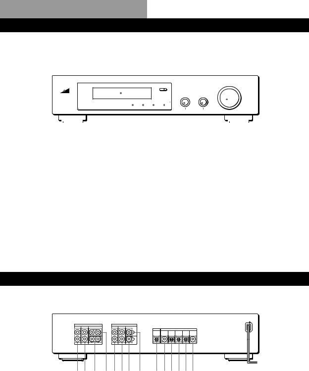
Front Panel Descriptions
1
|
|
|
|
|
|
|
|
|
|
|
|
|
|
|
|
|
|
|
|
|
|
|
|
|
|
|
|
|
|
|
|
|
|
|
|
|
|
|
|
|
|
|
|
|
|
|
|
|
|
|
|
|
|
|
|
|
|
|
|
|
|
|
|
|
|
|
|
|
|
|
|
|
|
|
|
|
|
|
|
|
|
|
|
|
|
|
|
|
|
|
|
|
|
|
|
|
|
|
|
|
|
|
|
|
|
|
|
|
|
|
|
|
|
|
|
|
|
|
|
|
|
|
|
|
|
|
|
|
|
|
|
|
|
|
|
|
|
|
|
|
|
|
|
|
|
|
|
|
|
|
|
|
|
|
|
|
|
|
|
|
|
|
|
|
|
|
|
|
|
|
|
|
|
|
|
|
|
|
|
|
|
|
|
|
|
|
|
|
|
|
|
|
|
|
|
|
|
|
|
|
|
|
|
|
|
|
|
|
|
|
|
|
|
|
|
|
|
|
|
|
|
|
|
|
|
|
|
|
|
|
|
|
|
|
|
|
|
|
|
|
|
|
|
|
|
|
|
|
|
|
|
|
|
|
|
|
|
|
|
|
|
|
|
|
|
|
|
|
|
|
|
|
|
|
|
|
|
|
|
|
|
|
|
|
|
|
|
|
|
|
|
|
|
|
|
|
||||
2 3 |
4 |
|
|
|
|
5 6 7 8 9 0 !¡ !™ |
||||||||||||||||||||||||||||||||||||
1 Display |
|
|
|
|
|
|
5 BASS BOOST |
|
|
|
|
9 SET UP |
||||||||||||||||||||||||||||||
2 POWER |
|
|
|
|
|
|
6 MPEG/DOLBY DIGITAL |
|
|
|
|
0 MENU |
||||||||||||||||||||||||||||||
3 Remote sensor (centre) |
|
|
|
|
|
|
7 MODE |
|
|
|
|
!¡ +/– |
||||||||||||||||||||||||||||||
4 INPUT selectors |
|
|
|
|
|
|
8 OFF |
|
|
|
|
|
|
|
|
|
|
|
|
|
|
|
!™ MASTER VOLUME |
|||||||||||||||||||
|
|
|
|
|
|
|
|
|
|
|
|
|
|
|
|
|
|
|
|
|
|
|
|
|
|
|
|
|
|
|
|
|
|
|
|
|
|
|
|
|
|
|
|
|
|
|
|
|
|
|
|
|
|
|
|
|
|
|
|
|
|
|
|
|
|
|
|
|
|
|
|
|
|
|
|
|
|
|
|
|
|
|
|
|
|
Rear Panel Descriptions
!
12 3 4567 8 90!¡!™!£!¢
1 FRONT L (left) and R (right) |
5 FRONT L (left) and R (right) |
9 DIGITAL OUTPUT (optical) |
OUTPUT |
BYPASS INPUT |
0 DIGITAL INPUT 4 (coaxial) |
2 REAR L (left) and R (right) |
6 REAR L (left) and R (right) |
!¡ DIGITAL INPUT 3 (optical) |
OUTPUT |
BYPASS INPUT |
!™ DIGITAL INPUT 2 (optical) |
3 WOOFER OUTPUT(s) |
7 WOOFER BYPASS INPUT |
!£ DIGITAL INPUT 1 (optical) |
4 CENTER OUTPUT(s) |
8 CENTER BYPASS INPUT |
!¢ AC-3 RF INPUT |
|
|
! Mains lead |
24GB

Index
Index
A
Adjusting
effect level 14 speaker volume 9 volume 11
Audio component hookups 4
B
Basic menu mode 15, 18
C
Centre speaker
cut off frequency 9, 19 distance 7, 9
mode (size) 8 placement 7 volume level 9 Connecting. See Hookups CUSTOMIZE menu 17
D
Digital Cinema Sound 13 Digital component hookups 6 Dolby Digital (AC-3) 23 Dolby Pro Logic Surround 23 Dolby Surround sound 23
E
EQUALIZER menu 17 Expand menu mode 15, 18
F, G
Front panel 24 Front speakers balance 9
cut off frequency 9, 19 distance 7, 9
mode (size) 8 placement 7
H, I, J, K
Hookups 4
L
LEVEL ADJUST menu 15
M, N, O
MPEG 23
Menu operations 15
P, Q
Programme source selecting 11
R
Rear panel 24 Rear speakers balance 9
cut off frequency 9, 19 distance 7, 9
mode (size) 8 placement 7 volume level 9
Recording
digital audio 14
S
Selecting a programme source using the remote 11
Set up procedure 8 Speakers
cut off frequency 9, 19 distance 7, 9
mode (size) 8 placement 7 volume level 9 set up 8
SP.SETUP menu 18 Sub woofer
connections 4, 5, 6 level 16
mode 9, 16 SURROUND menu 16
T
Test tone 9, 15
Tone controls 16
Troubleshooting 22
U, V, W, X, Y, Z
Unpacking 4
25GB

AVERTISSEMENT
Afin d’éviter tout risque d’incendie ou d’électrocution, éviter d’exposer l’appareil à la pluie ou à l’humidité.
Afin d’éviter tout risque d’incendie ou d’électrocution, éviter d’exposer l’appareil à la pluie ou à l’humidité.
N’installez pas l’appareil dans un espace confiné comme dans une bibliothèque ou un meuble encastré.
2F
|
En cas de question ou de problème |
|
Précautions |
||
concernant le processeur, consultez le |
||
|
revendeur Sony le plus proche. |
Sécurité
•Si un solide ou un liquide tombait dans le coffret, débranchez le processeur et faites-le vérifier par un technicien qualifié avant de le remettre en service.
Sources d’alimentation
•Avant de mettre en service le processeur, vérifiez que la tension de fonctionnement correspond à celle du courant secteur local. La tension de fonctionnement est indiquée sur la plaque signalétique à l’arrière du processeur.
•Le processeur n’est pas déconnecté de la source d’alimentation tant qu’il est branché sur une prise murale, même si vous le mettez hors tension.
•Si vous ne comptez pas utiliser le processeur pendant un certain temps, débranchez-le de la prise murale. Pour débrancher le cordon, tirez sur la fiche et jamais sur le cordon proprement dit.
•Le cordon d’alimentation secteur doit être changé par un professionnel seulement.
Installation
•N’installez pas le processeur près d’une source de chaleur, dans un endroit en plein soleil, poussiéreux ou exposé à des chocs mécaniques.
•Ne placez pas le processeur près d’une source de chaleur ou dans un endroit en plein soleil, poussiéreux ou subissant des chocs mécaniques.
•Ne posez rien sur le coffret qui puisse bloquer les orifices de ventilation et provoquer un mauvais fonctionnement.
Fonctionnement
•Avant de raccorder d’autres appareils, mettez le processeur hors tension et débranchez-le.
Nettoyage
•Nettoyez le coffret, le panneau et les commandes avec un chiffon doux légèrement imprégné d’une solution détergente douce. N’utilisez pas de tampon abrasif, poudre à récurer ou solvant, comme de l’alcool ou de la benzine.

Au sujet de ce manuel
Conventions
•Ce mode d’emploi décrit le fonctionnement avec les commandes du processeur. Vous pouvez également utiliser les commandes de la télécommande qui ont un nom identique ou similaire à celles du processeur.
•Les symboles suivants sont utilisés dans ce manuel:
Indique que vous pouvez utiliser
la télécommande pour effectuer cette opération.
 Donne des conseils
  supplémentaires pour faciliter l’utilisation.
Ce processeur utilise le système surround Dolby Pro Logic. Fabriqué sous licence de Dolby Laboratories Licensing Corporation.
DOLBY, le symbole double-D a, PRO LOGIC et “AC-3” sont des marques de Dolby Laboratories Licensing Corporation.
TABLE DES MATIÈRES
Préparatifs
Déballage 4
Branchement du système 4
Disposition des haut-parleurs 7
Avant d’utiliser votre processeur 7
Installation des haut-parleurs 8
Fonctionnement du processeur
Sélection d’un composant 11
Sélection d’un Champ Surround 12
Enregistrement numérique 14
Réglages et ajsutements 15
Compréhension de l’affichage 20
Informations supplémentaires
Guide de dépannage 22
Données techniques 23
F
Glossaire 23
Nomenclature du panneau avant 24
Nomenclature du panneau arrière 24
Index 25
3F
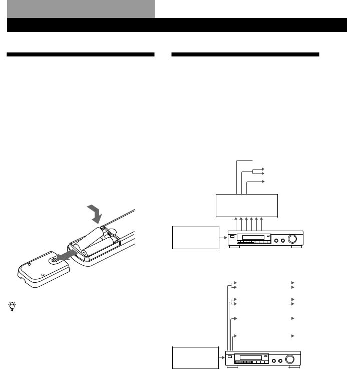
Préparatifs
Déballage
Vérifiez si les accessoires suivants se trouvent dans l’emballage.
•Télécommande (1)
•Piles de format AA (R6) (2)
•Cordons de connexion (3)
Mise en place des piles dans la télécommande
Insérez deux piles de format AA (R6) en faisant correspondre les bornes + et – avec le schéma dans le logement. Pour utiliser la télécommande, dirigez-la vers le détecteur infrarouge gsur le processeur.
|
] |
|
} |
} |
|
] |
||
|
Quand remplacer les piles
Dans des conditions d’utilisation normales, les piles durent environ six mois. Quand vous ne pouvez plus contrôler le processeur avec la télécommande, remplacez les piles par des neuves.
Remarques
•Ne laissez pas la télécommande dans un endroit extrêmement chaud ou humide.
•N’utilisez pas en même temps une pile neuve et une pile usée.
•Ne pas exposer le détecteur infrarouge aux rayons directs du soleil ou à un dispositif d’éclairage afin d’éviter tout mauvais fonctionnement.
•Si vous prévoyez de ne pas utiliser la télécommande pendant longtemps, enlevez les piles pour éviter tout dommage dû à une fuite d’électrolyte et à la corrosion.
4F
Branchement du système
Le Processeur Surround vous permet de raccorder jusqu’à 5 composants de source audio (ou vidéo) numérique, tels qu’une platine DVD ou un lecteur LD, avec une sortie AC-3 RF. L’illustration indique comment effectuer les branchements entre vos composants de source audio (ou vidéo) numérique, le processeur surround et votre amplificateur multicanaux.
• Branchement d’un ampli à entrées de canal 5.1
 Haut-parleurs avant
Haut-parleurs arrière
Haut-parleur central  Subwoofer
Ampli compatible MPEG ou Dolby Digital (AC-3)
(TA-VA8ES, etc.)
Platine DVD, lecteur LD, etc.
•Branchement d’amplis séparés pour chaque hautparleur
|
|
|
Haut- |
Ampli pour haut- |
|
|
|
|
|
parleurs |
|
|
|
||
parleurs avant |
|
|
avant |
|
|
||
|
|
|
Haut- |
|
|
|
|
Ampli pour haut- |
|
|
|
|
|
parleurs |
|
|
|
||
parleurs arrière |
|
|
|
|
|
arrière |
|
|
|
|
Haut- |
Ampli pour haut- |
|
|
|
parleur central |
|
|
parleur |
|
|
central |
|
|
|
|
|
|
|
|
|
Ampli pour |
|
|
Subwoofer |
subwoofer |
|
|
|
|
|
|
|
|
|
|
|
Platine DVD, lecteur LD, etc.
1Raccordez les bornes de sortie (OUTPUT) du processeur surround sur les entrées des canaux avant (gauche et droit), arreére (gauche et droit) central et de subwoofer de votre amplificateur. (Pour le TA-VA8ES/TA-VA70, raccordez aux bornes 5.1 INPUT comme illustré à la page suivante.)
2Raccordez les sorties audio numériques de chaque composant sur les bornes adéquates à l’arrière du processeur surround.
Les entrées numériques de cet appareil détectent automatiquement les signaux MPEG, Dolby Digital (AC-3), ou PCM.
La borne d’entrée AC-3 RF destinée à un emploi avec les lecteurs LD est réservée aux signaux Dolby Digital (AC-3) uniquement.

Préparatifs
Branchement d’un ampli à entrée de canal 5.1(comme le Sony TA-VA8ES/TA-VA70, etc.)
|
depuis sortie |
|
AUDIO/VIDEO |
Platine DVD, etc.* |
OUT |
|
depuis sortie |
|
AUDIO/VIDEO |
Lecteur LD ** |
OUT |
ç |
La flèche çindique le parcours du signal. |
ç
TA-VA8ES/TA-VA70
TV |
LD |
VIDEO 2 |
VIDEO 1 |
MONITOR |
|
depuis |
Lecteur CD, etc. |
OUTPUT |
|
IN |
IN |
OUT |
IN |
OUT |
IN |
OUT |
|
|
|
|
|
|
|
|
|
|
|
|
|
|
|
|
FRONT |
SPEAKERS |
|
|
|
|
|
|
|
|
|
|
|
|
SWITCHED AC OUTLETS |
|
VIDEO |
VIDEO |
VIDEO |
VIDEO |
VIDEO |
VIDEO |
|
|
|
|
|
|
|
IN |
IN |
OUT |
IN |
OUT |
IN |
OUT 2 |
OUT 1 |
|
|
|
|
|
AUDIO |
AUDIO |
AUDIO |
AUDIO |
AUDIO |
AUDIO |
|
|
|
|
|
|
|
IN |
IN |
OUT |
IN |
OUT |
IN |
|
|
|
|
|
|
|
|
|
|
|
|
|
|
|
|
|
CENTER SPEAKER |
REAR SPEAKERS |
y |
|
|
|
|
|
|
|
5.1 INPUT |
|
SURROUND OUT |
|
|
|
|
|
|
|
|
FRONT |
REAR |
CENTER |
REAR |
CENTER |
|
|
IN |
IN |
IN |
REC OUT |
IN |
REC OUT |
IN |
|
|
WOOFER |
|
WOOFER |
|
PHONO |
TUNER |
CD |
DAT/MD |
TAPE |
|
|
|
|
|
|
||
ç |
à une prise |
|
secteur |
à INPUT
Platine DAT/MD
depuis OUTPUT
ç
ç
ç
ç
ç
ç
SDP-EP90ES/EP70
|
OUTPUT |
|
|
BYPASS INPUT |
|
|
|
|
|
FRONT |
REAR |
CENTER |
FRONT |
REAR |
CENTER |
|
|
|
|
L |
L |
|
L |
L |
OUTPUT |
|
INPUT |
|
|
|
|
|
|
|
|
|
|
||
|
|
|
|
|
DIGITAL DIGITAL |
DIGITAL |
DIGITAL |
DIGITAL |
AC-3 |
|
|
|
|
|
4 |
3 |
2 |
1 |
RF |
R |
R |
WOOFER |
R |
R |
WOOFER |
|
|
|
|
à l’entrée OPTICAL DIGITAL INPUT |
ç |
|
|
|
à une prise |
||||
|
ç |
|||
depuis OPTICAL DIGITAL OUTPUT |
secteur |
|||
depuis COAXIAL DIGITAL OUTPUT |
ç |
|
|
|
depuis OPTICAL DIGITAL OUTPUT * |
ç |
|
|
|
depuis AC-3 RF OUTPUT |
ç |
|
|
|
Remarques sur les branchements
•Ne branchez pas le cordon d’alimentation sur une prise secteur et n’appuyez pas sur l’interrupteur U (POWER) avant d’avoir achevé tous les branchements.
•Les connecteurs de câble doivent être insérés à fond dans les prises, car des branchements relâchés peuvent causer un ronflement ou des parasites.
•Les prises et les fiches des cordons de branchement sont codées selon les couleurs suivantes:
Prises et fiches jaunes: Signal vidéo Prises et fiches rouges: Canal audio droit
Prises et fiches blanches: Canal audio gauche
Vous pouvez utiliser indifféremment les cèbles rouges ou blancs pour raccorder le haut-parleur central et le subwoofer.
*Si votre lecteur DVD possède une sortie COAXIAL DIGITAL OUPTUT, il est conseillé de raccorder l’entrée COAXIAL DIGITAL INPUT du lecteur DVD sur l’entrée DIGITAL INPUT 4 (COAXIAL IN) de cet appareil au lieu d’effectuer la connexion optique indiquée ci-avant.
**Si votre lecteur LD possède une sortie optonumérique, raccordez-la sur les prises DIGITAL OUTPUT 1~3 de cet appareil. Ce branchement peut être utilisé en même temps que la connexion AC-3 RF.
(continuer page suivante)
5F
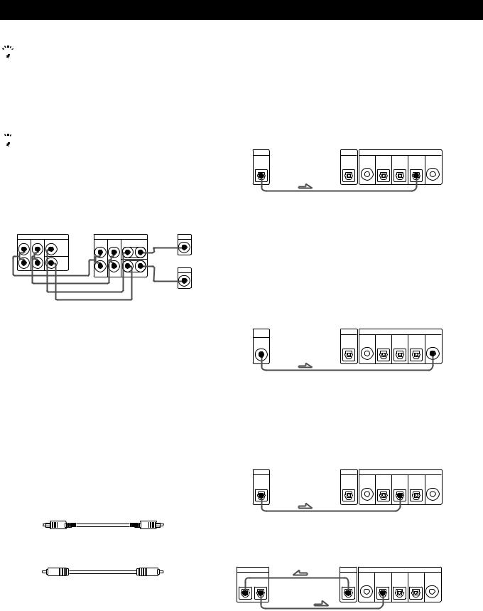
Préparatifs
 Si vous avez un ampli surround supplémentaire à bornes de pré-sortie (tel que le Sony TA-E2000ESD)
Vous pouvez le raccorder aux prises BYPASS INPUT de cet appareil. Les signaux provenant de l’ampli raccordé seront alors fournis sans altération au niveau des prises OUTPUT de cet appareil quand vous choisirez BYPASS (cf. page 11 pour les détails).

 Si vous avez un haut-parleur central ou un subwoofer actif supplémentaire
Branchez l’autre borne CENTER OUTPUT sur l’entrée de l’amplificateur pour votre autre haut-parleur central. Branchez l’autre borne WOOFER OUTPUT sur la borne d’entrée du woofer actif.
|
|
|
|
|
Ampli pour haut- |
TA-VA8ES |
SDP-EP90ES/EP70 |
parleur central |
|||
5.1 INPUT |
|
|
OUTPUT |
|
INPUT |
FRONT REAR |
CENTER |
FRONT |
REAR |
CENTER |
ç |
|
|
L |
L |
|
|
|
WOOFER |
|
|
|
|
|
|
ÇÇ R |
|
|
INPUT |
|
|
R |
WOOFER |
ç |
|
|
|
Ç |
|
|
|
|
|
Ç |
|
|
Woofer actif |
Branchement de composants numériques
Vous pouvez raccorder les prises de sortie numérique d’une platiane DVD, d’une platine DAT/MD, d’un lecteur CD, etc. sur les prises d’entrée numérique (DIGITAL INPUT 1-4) du processeur surround.
Vous pouvez également raccorder la borne de sortie AC-3 RF d’un lecteur LD sur la borne d’entrée AC-3 RF INPUT du processeur surround.
Vous pouvez raccorder la prise de sortie numérique (DIGITAL OUTPUT) du processeur surround sur une platine DAT/MD.
Quels cordons sont nécessaires?
•Cordon de branchement opto-numérique (non fourni)
•Cordon de branchement numérique coaxial (non fourni)
Branchements
La flèche çindique le parcours du signal.
Lecteur DVD
Veillez à raccorder la sortie numérique du lecteur DVD sur une des prises DIGITAL INPUT 1~4 du processeur surround.
Platine DVD |
Processeur surround |
|
|||
DIGITAL |
OUTPUT |
|
INPUT |
|
|
|
DIGITAL DIGITAL |
DIGITAL |
DIGITAL |
DIGITAL |
AC-3 |
|
4 |
3 |
2 |
1 |
RF |
OUT |
|
|
|
|
|
Si votre lecteur DVD possède une sortie COAXIAL DIGITAL OUTPUT, il est conseillé de raccorder l’entrée COAXIAL DIGITAL INPUT du lecteur DVD sur l’entrée DIGITAL INPUT 4 (COAXIAL IN) de cet appareil au lieu d’effectuer la connexion optique indiquée ci-avant.
Lecteur LD
Veillez à raccorder la sortie AC-3 RF du lecteur LD sur les prises AC-3 RF INPUT du processeur surround.
Lecteur LD |
|
Processeur surround |
|
|||
AC-3 |
OUTPUT |
|
|
INPUT |
|
|
RF |
DIGITAL |
DIGITAL |
DIGITAL |
DIGITAL |
DIGITAL |
AC-3 |
|
||||||
|
|
4 |
3 |
2 |
1 |
RF |
OUT |
|
|
|
|
|
|
Si votre lecteur LD a une sortie opto-numérique, raccordezla à une des prises DIGITAL INPUT 1~3 de cet appareil. Ce branchement peut être utilisé en même temps que la connexion AC-3 RF.
Lecteur CD
Lecteur CD |
Processeur surround |
|
|||
DIGITAL |
OUTPUT |
|
INPUT |
|
|
|
DIGITAL DIGITAL |
DIGITAL |
DIGITAL |
DIGITAL |
AC-3 |
|
4 |
3 |
2 |
1 |
RF |
OUT |
|
|
|
|
|
Platine DAT/MD
Platine DAT/MD |
|
Processeur surround |
||||
DIGITAL |
OUTPUT |
|
|
INPUT |
|
|
|
DIGITAL |
DIGITAL |
DIGITAL |
DIGITAL |
DIGITAL |
AC-3 |
|
|
4 |
3 |
2 |
1 |
RF |
IN OUT |
|
|
|
|
|
|
Remarque
Cet appareil est compatible uniquement avec des composants numériques, utilisant des fréquences d’échantillonnage de 32 kHz, 44,1 kHz ou 48 kHz. Il n’est pas compatible avec la fréquence de 96 kHz.
6F
 Loading...