


2-630-291-12(1)
TFT LCD Color
Computer Display
Quick Setup Guide |
|
|
|
US |
|
Setup . . . . . . . . . . . . . . . . . . . |
. . . . . . . . . . . . . . . . . . .3 (US) |
||||
Troubleshooting . . . . . . . . . . . |
. . . . . . . . . . . . . . . . . . .6 (US) |
||||
Guide de configuration rapide |
|
FR |
|||
Installation . . . . . . . . . . . . . . . |
. . . . . . . . . . . . . . . . . . .3 (FR) |
||||
Dépannage . . . . . . . . . . . . . . |
. . . . . . . . . . . . . . . . . . .6 (FR) |
||||
Guía de instalación rápida |
|
|
ES |
||
Configuración. . . . . . . . . . . . . |
. . . . . . . . . . . . . . . . . . 3 (ES) |
||||
Resolución de problemas . . . |
. . . . . . . . . . . . . . . . . . .6 (ES) |
||||
|
|
|
|
|
CS |
. . . . |
. . . . . |
. . . . . . . . |
. . . |
. . . . . . . . . . . . . . . . . . .3 (CS) |
|
|
|
. . . . |
. . . |
. . . . . . . . . . . . . . . . . . .6 (CS) |
|
DO NOT RETURN TO PLACE OF PURCHASE NE PAS RETOURNER AU MAGASIN
If you believe the product purchased in the U.S. is defective, call Sony for assistance or Advance Exchange. For assistance in the U.S. call: 1-866-357-SONY (7669) For assistance in Canada call: 1-800-961-SONY (7669)
Si vous croyez que le produit acheté aux E.-U. est defectueux, communiquer avec Sony pour obtenir de l’aide ou un remplacement.
Pour obtenir de l’aide aux E.-U., composer le : 1-866-357-SONY (7669) Pour obtenir de l’aide au Canada, composer le :1-800-961-SONY (7669)
Si usted compro’ este producto en E.E.U.U. y necesita asistencia, no regrese el producto comuniquese al 1-866-357-SONY (7669).
http://www.sony.com/displays/support
SDM-S75 
SDM-S95 
© 2005 Sony Corporation
Owner’s Record
The model and serial numbers are located at the rear of the unit. Record these numbers in the spaces provided below. Refer to them whenever you call upon your dealer regarding this product.
Model No. Serial No.
WARNING
To reduce the risk of fire or electric shock, do not expose this apparatus to rain or moisture. Dangerously high voltages are present inside the unit. Do not open the cabinet. Refer servicing to qualified personnel only.
Precautions
Warning on power connections
•Use the supplied power cord. If you use a different power cord, be sure that it is compatible with your local power supply.
For the customers in the U.S.A.
If you do not use the appropriate cord, this display will not conform to mandatory FCC standards.
For the customers in the UK
If you use the display in the UK, be sure to use the appropriate UK power cord.
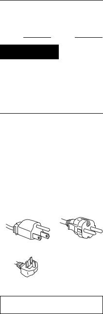
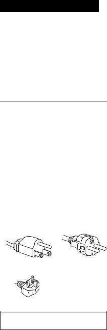
Example of plug types
for 100 to 120 V AC for 200 to 240 V AC
for 240 V AC only
The equipment should be installed near an easily accessible outlet.
2 (US)
Installation
Do not install or leave the display:
•In places subject to extreme temperatures, for example near a radiator, heating vent, or in direct sunlight. Subjecting the display to extreme temperatures, such as in an automobile parked in direct sunlight or near a heating vent, could cause deformations of the casing or malfunctions.
•In places subject to mechanical vibration or shock.
•Near any equipment that generates a strong magnetic field, such as a TV or various other household appliances.
•In places subject to inordinate amounts of dust, dirt, or sand, for example near an open window or an outdoor exit. If setting up temporarily in an outdoor environment, be sure to take adequate precautions against airborne dust and dirt. Otherwise irreparable malfunctions could occur.
Note on the LCD (Liquid Crystal Display)
Please note that the LCD screen is made with high-precision technology. However, black points or bright points of light (red, blue, or green) may appear constantly on the LCD screen, and irregular colored stripes or brightness may appear on the LCD screen. This is not malfunction.
(Effective dots: more than 99.99%)
Transportation
•Disconnect all the cables from the display. If you use a height adjustable stand adjust its height to the highest position and hold both sides of the LCD display securely.
Be careful not to scratch the screen when transporting. If you drop the display, you may injured or the display may be damaged.
•When you transport this display for repair or shipment, use the original carton and packing materials.
•Replace the stopper pin for the height adjustable stand to fix the stand during the transportation.
For customers in the United States
This product contains mercury. Disposal of this product may be regulated if sold in the United States. For disposal or recycling information, please contact your local authorities or the Electronics Industries Alliance (http://www.eiae.org).
3Select the region and model first. And then select and open the “Operating Instructions (PDF) .”
To exit from the CD-ROM
Click “EXIT/CD.ROM.”
To view the Operating Instructions on the CDROM
Note
To view the Operating instructions, you are required to have Macromedia Shockwave Player and Adobe Acrobat Reader (version 6.0 or later) on your computer. The supplied CD-ROM contains installing software for Windows. To get the software installed on your computer, open “My Computer” and right-click the CD-ROM icon and select “Explorer.” Select the application from the “installs” folder and then install it on your computer. Once you have your installation completed the CD-ROM starts automatically.
For Windows User
When the CD-ROM auto-runs:
Select the region and model first. And then select and open the “Operating Instructions (PDF) .”
When the CD-ROM fails to auto run:
1Open “My Computer.”
2Right-click “CD-ROM” and select “Explorer.” 3Open the “Manuals” folder in Windows.
4Select and open “S_75_95_GB.pdf.”
For Macintosh User:
1Double-click the CD-ROM icon.
2Double-click “MONITOR.”
Setup
Unpacking
Make sure your carton contains everything listed below.
•LCD display
•Power cord
• Stand Base |
US |
•HD15-HD15 video signal cable (analog RGB)
•DVI-D video signal cable (digital RGB) 
•Audio cord (stereo miniplug)
•CD-ROM (utility software for Windows/ Macintosh, Operating Instructions, etc.)
•Warranty card
•This Quick Setup Guide
The contents with  mark for specifications vary depending on the models. For details, see “Specifications”.
Connecting your display
Connect your display to a computer or other equipment.
•Turn off the display, computer, and any other equipment before connecting them.
•Do not touch the pins of the video signal cable plug.
1 Assemble the stand.
Do not press the LCD display when placing or raising the display straight on a desk or a like.
It may affect the uniformity of the screen or damage the LCD display.
3 (US)

Refer to an enclosed instruction,“Assemble the stand,” for assembling the stand.
2 Tilt the display up.
When using the height adjustable stand, raise the display higher.
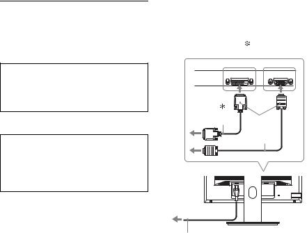
3 Connect your display to a computer.
If you use the fixed stand, draw the video signal cables through the stand hole first and then connect them to the display.
Connecting a Macintosh computer
Connect the supplied video signal cable to a video output connector on the computer. If necessary, use an adapter (not supplied). Connect the adapter to the computer before connecting the video signal cable.
4 Connect the supplied power cord securely to the display’s AC IN connector.
5 Connect the other end securely to a power outlet.
to the DVI-D input |
to the HD15 |
connector |
input connector |
(digital RGB) |
(analog RGB) |
INPUT 1 |
INPUT 2 |
DVI-D |
HD-15 |
DVI-D video |
3 |
signal cable |
|
(digital RGB) |
HD15-HD15 |
(supplied) |
|
|
video signal |
|
cable |
|
(analogRGB) |
|
(supplied) |
4 toAC IN 

to power outlet
5
power cord (supplied)
 Digital model only
6 Secure the cords
xFixed Stand
Be sure that the cords and cables have been drawn into the stand hole as illustrated.
xHeight adjustable stand
Draw the cords and cables through the cable holder as illustrated.
Notes
•Slide up the cable holder of the height adjustable stand to open as illustrated.
•When bounding the cords and cables, be sure to loosen them a little. If they get pulled hard they may come off from the connectors or plugs as you adjust the screen angle. If you stretch the cords and cables too hard they may get damaged.
4 (US)
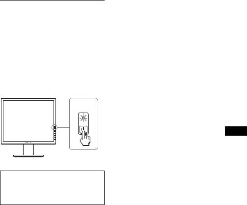
Turn on the display and computer
1 Press the 1 (power) switch located on the front right of the display.
The 1 (power) indicator lights up in green.
2 Turn on the computer.
1
lights in green
US
No need for specific drivers
The display complies with the “DDC” Plug & Play standard and automatically detects all the display’s information. No specific driver needs to be installed on the computer.
5 (US)

Troubleshooting
Trouble symptoms and remedies (If no picture appears on the screen)
If no picture appears on the screen, check the following table for possible solutions. If you are experiencing difficulties not listed below, refer to the Operating Instructions on the supplied CD-ROM. For problems caused by a computer or other equipment, refer to the user’s manuals supplied with the respective items.
Symptom |
Check these items |
|
|
If the 1 (power) |
• Check that the 1 (power) switch is on. |
|
indicator is not lit, |
|
|
or, 1 (power) |
|
|
indicator turns on in |
|
|
orange, |
|
|
|
|
|
If the 1 (power) |
• Check that the power cord is properly connected. |
|
indicator will not |
|
|
light up when the 1 |
|
|
(power) switch is |
|
|
pressed, |
|
|
|
|
|
If “CABLE |
• Check that the video signal cable is properly connected and |
|
DISCONNECTED” |
all plugs are firmly seated in their sockets (page 3 (US)). |
|
appears on the |
• Check that the video input connector’s pins are not bent or |
|
screen, |
pushed in. |
|
|
• Check that the input select setting is correct (For details, refer |
|
|
to the Operating Instructions on the supplied CD-ROM). |
|
|
• A non-supplied video signal cable is connected. If you |
|
|
connect a non-supplied video signal cable, “CABLE |
|
|
DISCONNECTED” may appear on the screen. This is not a |
|
|
malfunction. |
If “NO INPUT SIGNAL” appears on the screen, or, 1 (power) indicator turns on in orange,
•Check that the video signal cable is properly connected and all plugs are firmly seated in their sockets (page 3 (US)).
•Check that the video input connector’s pins are not bent or pushed in.
•Check that the input select setting is correct (For details, refer
to the Operating Instructions on the supplied CD-ROM).
xProblem caused by a computer or other equipment connected, and not caused by the display
•The computer is in the power saving mode. Try pressing any key on the keyboard or moving the mouse.
•Check that your graphics board is installed properly.
•Check that the computer’s power is on.
•Restart the computer.
6 (US)

Symptom |
Check these items |
|
||
|
If “OUT OF |
x Problem caused by a computer or other equipment |
|
|
|
RANGE” appears on |
connected, and not caused by the display |
|
|
|
the screen, |
• Check that the video frequency range is within that specified |
|
|
|
for the display. If you replaced an old display with this |
|
||
|
|
|
||
|
|
display, reconnect the old display and adjust the computer’s |
|
|
|
|
graphics board within the following ranges: |
|
|
|
|
Horizontal frequency: 28–80 kHz (analog RGB), 28–64 kHz |
|
|
|
|
(digital RGB) |
|
|
|
|
Vertical frequency: 48–75 Hz (analog RGB), 60 Hz (digital |
|
|
|
|
RGB) |
|
|
|
|
Resolution: 1280 × 1024 or less |
|
|
|
|
|
|
|
|
If you are using |
• If you replaced an old display with this display, reconnect the |
|
|
|
Windows and |
old display and do the following. Select “SONY” from the |
|
|
|
replaced an old |
“Manufacturers” list and select the desired model name from |
|
|
|
display with this |
|
||
|
the “Models” list in the Windows device selection screen. If |
|
||
|
display, |
|
||
|
the model name of this display does not appear in the |
|
||
|
|
|
||
|
|
“Models” list, try “Plug & Play.” |
|
|
|
|
US |
||
|
|
|
|
|
|
If using a Macintosh |
• When connecting a Macintosh computer, use an adapter (not |
||
|
|
|||
|
system, |
supplied) if necessary. Connect the adapter to the computer |
|
|
|
|
before connecting the video signal cable. |
|
|
|
|
|
|
|
7 (US)
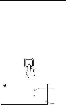
Displaying this display’s information
While the display is receiving a video signal, press and hold the MENU button for more than 5 seconds until the information box appears.
Press the MENU button again to make the box disappear.
MENU
Example
INFORMATION |
|
Model |
|
|
|
|
|
MODEL : SDM-S75A |
|
name |
|
|
Serial |
||
SER. NO : 1234567 |
|
|
|
|
|
||
MANUFACTURED : 2005-52 |
|
number |
|
|
|
|
Week and |
|
|
|
|
|
|
|
year of |
|
|
|
manufacture |
Although the safety standard registered model name of this display is SDM-S75 / S95
/ S95 , the name of SDM-S75A/S95A/ S75D/S95D/S75E/S95E/S75F/S95F/S75N/ S95N is used on sale.
If any problem persists, call your authorized Sony dealer and give the following information:
•Model name
•Serial number
•Detailed description of the problem
•Date of purchase
•Name and specifications of your computer and graphics board
•Type of input signals (analog RGB/digital RGB)
8 (US)

Specifications
Model name |
SDM-S75A |
SDM-S95A |
|
||
|
|
|
|
||
LCD panel |
Panel type: a-Si TFT Active Matrix |
||||
|
|
|
|
|
|
Picture size: inch |
17.0 |
19.0 |
|
|
|
|
|
|
|
|
|
Input signal format |
RGB operating |
frequency1) |
|
|
|
|
Horizontal: 28 – 80 kHz |
|
|
|
|
|
Vertical: 48 – 75 Hz |
|
|
|
|
|
|
|
|
|
|
Resolution |
Horizontal: Max.1280 dots |
|
|
|
|
|
Vertical: Max.1024 lines |
|
|
|
|
|
|
|
|
|
|
Type of input signal |
Analog ×1 |
|
|
|
|
(Digital/Analog) |
|
|
|
||
|
|
|
|
|
|
|
|
||||
Input signal levels |
Analog RGB video signal 0.7 Vp-p, 75 Ω, positive |
|
|||
|
SYNC signal TTL level, 2.2 kΩ, positive or negative |
||||
Audio input |
Stereo minijack, 0.5 Vrms |
|
|
|
|
|
|
US |
|||
|
|
|
|
|
|
Audio output |
Stereo minijack |
|
|
|
|
|
|
|
|||
Power requirements |
100 – 240 V, 50 – 60 Hz, Max. 1.0 A |
||||
|
|
|
|
||
Power consumption |
Max. 45 W |
Max. 50 W |
|||
|
|
|
|
|
|
Operating temperature |
5 – 35 °C |
|
|
|
|
|
|
|
|
||
Type of the stand |
Fixed |
Fixed |
|||
|
|
|
|
||
Dimensions (width/height/ |
Approx. 369 × 423.5 × 225 |
Approx. 414 × 439.5 × 225 |
|||
depth) |
mm (14 5/8 × 16 3/4 × 8 7/8 |
mm (16 3/8 × 17 3/8 × 8 7/8 |
|||
|
inches) (with stand) |
inches) (with stand) |
|||
|
Approx. 369 × 315 × 66 mm |
Approx. 414 × 348 × 69 mm |
|||
|
(14 5/8 × 12 3/8 × 2 5/8 |
(16 3/8 × 13 3/4 × 2 3/4 |
|
|
|
|
inches) (without stand) |
inches) (without stand) |
|||
|
|
|
|
||
Mass |
Approx. 6.4 kg (14 lb 1 3/4 |
Approx. 7.3 kg (16 lb 1 1/2 |
|||
|
oz) (with stand) |
oz) (with stand) |
|||
|
Approx. 4.3 kg |
Approx. 5.2 kg |
|||
|
(9 lb 7 5/ oz) |
(11 lb 7 |
3/ oz) |
||
|
8 |
|
8 |
|
|
|
(without stand) |
(without stand) |
|||
|
|
|
|
|
|
Plug & Play |
DDC2B |
|
|
|
|
|
|
|
|
|
|
Accessories |
See page 3 (US). |
|
|
|
|
|
|
|
|
|
|
1)Recommended horizontal and vertical timing condition
•Horizontal sync width duty should be more than 4.8% of total horizontal time or 0.8 µs, whichever is larger.
•Horizontal blanking width should be more than 2.5 µsec.
•Vertical blanking width should be more than 450 µsec.
Design and specifications are subject to change without notice.
9 (US)
Model name |
SDM-S75E |
|
|
|
SDM-S95E |
|
||||
|
|
|
|
|
|
|||||
LCD panel |
Panel type: a-Si TFT Active Matrix |
|
|
|
||||||
|
|
|
|
|
|
|
|
|
|
|
Picture size: inch |
17.0 |
|
|
|
|
|
19.0 |
|
|
|
|
|
|
|
|
|
|||||
Input signal format |
RGB operating |
frequency1) |
|
|
|
|||||
|
|
|
Horizontal: 28 – 80 kHz |
|
|
|
||||
|
|
|
Vertical: 48 – 75 Hz |
|
|
|
||||
|
|
|
|
|
||||||
Resolution |
Horizontal: Max.1280 dots |
|
|
|
||||||
|
|
Vertical: Max.1024 lines |
|
|
|
|||||
|
|
|
|
|
|
|
|
|
|
|
Type of input signal |
|
|
|
Analog ×1 |
|
|
|
|||
(Digital/Analog) |
|
|
|
|
|
|
||||
|
|
|
|
|
|
|
|
|
|
|
|
|
|
||||||||
Input signal levels |
Analog RGB video signal 0.7 Vp-p, 75 Ω, positive |
|
||||||||
|
SYNC signal TTL level, 2.2 kΩ, positive or negative |
|
||||||||
|
|
|
|
|
|
|||||
Audio input |
|
Stereo minijack, 0.5 Vrms |
|
|
|
|||||
|
|
|
|
|
|
|
||||
Audio output |
|
|
Stereo minijack |
|
|
|
||||
|
|
|
|
|
||||||
Power requirements |
100 – 240 V, 50 – 60 Hz, Max. 1.0 A |
|
|
|
||||||
|
|
|
|
|
|
|
||||
Power consumption |
Max. 45 W |
|
|
|
Max. 50 W |
|
||||
|
|
|
|
|
|
|
|
|
||
Operating temperature |
|
|
|
5 – 35 °C |
|
|
|
|||
|
|
|
|
|
|
|
||||
Type of the stand |
Height adjust |
|
|
|
Height adjust |
|
||||
|
|
|
||||||||
Dimensions (width/height/ |
Approx. 369 × 393.5 – 503.5 |
Approx. 414 × 409.5 – 519.5 |
||||||||
depth) |
× 253 mm (14 5/ |
8 |
× 15 |
1/ |
2 |
– |
× 277.5 mm (16 3/ |
8 |
× 16 1/ |
– |
|
|
|
|
|
|
|
8 |
|||
|
19 7/8 × 10 inches) (with |
|
20 1/2 × 11 inches) (with |
|||||||
|
stand) |
|
|
|
|
stand) |
|
|
|
|
|
Approx. 369 × 315 × 66 mm |
Approx. 414 × 348 × 69 mm |
||||||||
|
(14 5/8 × 12 3/8 × 2 5/8 |
|
(16 3/8 × 13 3/4 × 2 3/4 |
|
||||||
|
inches) (without stand) |
|
inches) (without stand) |
|||||||
|
|
|
||||||||
Mass |
Approx. 7.5 kg (16 lb 8 1/2 |
Approx. 8.7 kg (19 lb 2 7/8 |
||||||||
|
oz) (with stand) |
|
|
|
oz) (with stand) |
|
||||
|
Approx. 4.3 kg |
|
|
|
Approx. 5.2 kg |
|
||||
|
(9 lb 7 5/8 oz) |
|
|
|
(11 lb 7 3/8 oz) |
|
||||
|
(without stand) |
|
|
|
(without stand) |
|
||||
|
|
|
|
|
|
|
|
|
|
|
Plug & Play |
|
|
|
|
DDC2B |
|
|
|
||
|
|
|
|
|
|
|
||||
Accessories |
|
|
See page 3 (US). |
|
|
|
||||
|
|
|
|
|
|
|
|
|
|
|
1)Recommended horizontal and vertical timing condition
•Horizontal sync width duty should be more than 4.8% of total horizontal time or 0.8 µs, whichever is larger.
•Horizontal blanking width should be more than 2.5 µsec.
•Vertical blanking width should be more than 450 µsec.
Design and specifications are subject to change without notice.
10 (US)
Model name |
SDM-S75D |
SDM-S95D |
|
||
|
|
|
|
||
LCD panel |
Panel type: a-Si TFT Active Matrix |
||||
|
|
|
|
|
|
Picture size: inch |
17.0 |
19.0 |
|
|
|
|
|
|
|
|
|
Input signal format |
RGB operating |
frequency1) |
|
|
|
|
Horizontal: 28 – 80 kHz (analog RGB) |
||||
|
28 – 64 kHz (digital RGB) |
||||
|
Vertical: 48 – 75 Hz (analog RGB) |
||||
|
60 Hz (digital RGB) |
|
|
|
|
|
|
|
|
|
|
Resolution |
Horizontal: Max.1280 dots |
|
|
|
|
|
Vertical: Max.1024 lines |
|
|
|
|
|
|
|
|
|
|
Type of input signal |
Digital × 1/Analog × 1 |
|
|
|
|
(Digital/Analog) |
|
|
|
||
|
|
|
|
|
|
|
|
||||
Input signal levels |
Analog RGB video signal 0.7 Vp-p, 75 Ω, positive |
|
|||
|
SYNC signal TTL level, 2.2 kΩ, positive or negative |
||||
|
Digital RGB (DVI) signal TMDS (single link) |
||||
|
|
|
|
|
|
Audio input |
Stereo minijack, 0.5 Vrms |
|
|
|
|
|
|
US |
|||
|
|
|
|
|
|
Audio output |
Stereo minijack |
|
|
||
|
|
|
|||
|
|
|
|||
Power requirements |
100 – 240 V, 50 – 60 Hz, Max. 1.0 A |
||||
|
|
|
|
||
Power consumption |
Max. 45 W |
Max. 50 W |
|||
|
|
|
|
|
|
Operating temperature |
5 – 35 °C |
|
|
|
|
|
|
|
|
||
Type of the stand |
Fixed |
Fixed |
|||
|
|
|
|
||
Dimensions (width/height/ |
Approx. 369 × 423.5 × 225 |
Approx. 414 × 439.5 × 225 |
|||
depth) |
mm (14 5/8 × 16 3/4 × 8 7/8 |
mm (16 3/8 × 17 3/8 × 8 7/8 |
|||
|
inches) (with stand) |
inches) (with stand) |
|||
|
Approx. 369 × 315 × 66 mm |
Approx. 414 × 348 × 69 mm |
|||
|
(14 5/8 × 12 3/8 × 2 5/8 |
(16 3/8 × 13 3/4 × 2 3/4 |
|
|
|
|
inches) (without stand) |
inches) (without stand) |
|||
|
|
|
|
||
Mass |
Approx. 6.4 kg (14 lb 1 3/4 |
Approx. 7.3 kg (16 lb 1 1/2 |
|||
|
oz) (with stand) |
oz) (with stand) |
|||
|
Approx. 4.3 kg |
Approx. 5.2 kg |
|||
|
(9 lb 7 5/ oz) |
(11 lb 7 |
3/ oz) |
||
|
8 |
|
8 |
|
|
|
(without stand) |
(without stand) |
|||
|
|
|
|
|
|
Plug & Play |
DDC2B |
|
|
|
|
|
|
|
|
|
|
Accessories |
See page 3 (US). |
|
|
|
|
|
|
|
|
|
|
1)Recommended horizontal and vertical timing condition
•Horizontal sync width duty should be more than 4.8% of total horizontal time or 0.8 µs, whichever is larger.
•Horizontal blanking width should be more than 2.5 µsec.
•Vertical blanking width should be more than 450 µsec.
Design and specifications are subject to change without notice.
11 (US)
Model name |
SDM-S75F |
|
|
SDM-S95F |
|
||||
|
|
|
|
|
|
||||
LCD panel |
Panel type: a-Si TFT Active Matrix |
|
|
|
|||||
|
|
|
|
|
|
|
|
|
|
Picture size: inch |
17.0 |
|
|
|
|
19.0 |
|
|
|
|
|
|
|
|
|
||||
Input signal format |
RGB operating |
frequency1) |
|
|
|
||||
|
Horizontal: 28 – 80 kHz (analog RGB) |
|
|
||||||
|
|
|
28 – 64 kHz (digital RGB) |
|
|
||||
|
Vertical: 48 – 75 Hz (analog RGB) |
|
|
|
|||||
|
|
|
60 Hz (digital RGB) |
|
|
|
|||
|
|
|
|
|
|||||
Resolution |
Horizontal: Max.1280 dots |
|
|
|
|||||
|
|
Vertical: Max.1024 lines |
|
|
|
||||
|
|
|
|
|
|
|
|
|
|
Type of input signal |
|
|
Digital |
× 1/Analog × 1 |
|
|
|
||
(Digital/Analog) |
|
|
|
|
|
||||
|
|
|
|
|
|
|
|
|
|
|
|
|
|||||||
Input signal levels |
Analog RGB video signal 0.7 Vp-p, 75 Ω, positive |
|
|||||||
|
SYNC signal TTL level, 2.2 kΩ, positive or negative |
|
|||||||
|
Digital RGB (DVI) signal TMDS (single link) |
|
|||||||
|
|
|
|
|
|
||||
Audio input |
|
Stereo minijack, 0.5 Vrms |
|
|
|
||||
|
|
|
|
|
|
|
|||
Audio output |
|
|
Stereo minijack |
|
|
|
|||
|
|
|
|
|
|||||
Power requirements |
100 – 240 V, 50 – 60 Hz, Max. 1.0 A |
|
|
|
|||||
|
|
|
|
|
|
||||
Power consumption |
Max. 45 W |
|
|
Max. 50 W |
|
||||
|
|
|
|
|
|
|
|
||
Operating temperature |
|
|
5 – 35 °C |
|
|
|
|||
|
|
|
|
|
|
||||
Type of the stand |
Height adjust |
|
|
Height adjust |
|
||||
|
|
|
|||||||
Dimensions (width/height/ |
Approx. 369 × 393.5 – 503.5 |
Approx. 414 × 409.5 – 519.5 |
|||||||
depth) |
× 253 mm (14 5/ |
8 |
× 15 1/ |
2 |
– |
× 277.5 mm (16 3/ |
8 |
× 16 1/ |
– |
|
|
|
|
|
8 |
||||
|
19 7/8 × 10 inches) (with |
|
20 1/2 × 11 inches) (with |
||||||
|
stand) |
|
|
|
stand) |
|
|
|
|
|
Approx. 369 × 315 × 66 mm |
Approx. 414 × 348 × 69 mm |
|||||||
|
(14 5/8 × 12 3/8 × 2 5/8 |
|
(16 3/8 × 13 3/4 × 2 3/4 |
|
|||||
|
inches) (without stand) |
|
inches) (without stand) |
||||||
|
|
|
|||||||
Mass |
Approx. 7.5 kg (16 lb 8 1/2 |
Approx. 8.7 kg (19 lb 2 7/8 |
|||||||
|
oz) (with stand) |
|
|
oz) (with stand) |
|
||||
|
Approx. 4.3 kg |
|
|
Approx. 5.2 kg |
|
||||
|
(9 lb 7 5/8 oz) |
|
|
(11 lb 7 3/8 oz) |
|
||||
|
(without stand) |
|
|
(without stand) |
|
||||
|
|
|
|
|
|
|
|
|
|
Plug & Play |
|
|
|
DDC2B |
|
|
|
||
|
|
|
|
|
|
|
|||
Accessories |
|
|
See page 3 (US). |
|
|
|
|||
|
|
|
|
|
|
|
|
|
|
1)Recommended horizontal and vertical timing condition
•Horizontal sync width duty should be more than 4.8% of total horizontal time or 0.8 µs, whichever is larger.
•Horizontal blanking width should be more than 2.5 µsec.
•Vertical blanking width should be more than 450 µsec.
Design and specifications are subject to change without notice.
12 (US)
Model name |
|
|
|
SDM-S75N |
|
|
|
SDM-S95N |
|
|
|
|||||||
|
|
|
|
|
|
|
|
|
|
|
|
|||||||
LCD panel |
|
|
|
Panel type: a-Si TFT Active Matrix |
|
|
|
|
|
|
||||||||
|
|
|
|
|
|
|
|
|
|
|
|
|
|
|
|
|||
Picture size: inch |
|
|
|
17.0 |
|
|
|
|
19.0 |
|
|
|
|
|
|
|||
|
|
|
|
|
|
|
|
|
|
|
|
|
|
|
||||
Input signal format |
|
|
|
|
RGB operating |
frequency1) |
|
|
|
|
|
|
|
|
||||
|
|
|
|
Horizontal: 28 – 80 kHz (analog RGB) |
|
|
|
|
|
|||||||||
|
|
|
|
|
|
|
28 – 64 kHz (digital RGB) |
|
|
|
|
|
||||||
|
|
|
|
Vertical: 48 – 75 Hz (analog RGB) |
|
|
|
|
|
|
||||||||
|
|
|
|
|
|
|
60 Hz (digital RGB) |
|
|
|
|
|
|
|
|
|||
|
|
|
|
|
|
|
|
|
|
|
|
|
|
|||||
Resolution |
|
|
|
|
Horizontal: Max.1280 dots |
|
|
|
|
|
|
|
|
|||||
|
|
|
|
|
Vertical: Max.1024 lines |
|
|
|
|
|
|
|
|
|||||
|
|
|
|
|
|
|
|
|
|
|
|
|
|
|
|
|
|
|
Type of input signal |
|
|
|
|
Digital × 1/Analog |
× 1 |
|
|
|
|
|
|
|
|
||||
(Digital/Analog) |
|
|
|
|
|
|
|
|
|
|
|
|
||||||
|
|
|
|
|
|
|
|
|
|
|
|
|
|
|
|
|
|
|
|
|
|
|
|
|
|
|
|
|
|
|
|
|
|||||
Input signal levels |
|
|
|
|
Analog RGB video signal |
|
|
|
|
|
|
|
|
|||||
|
|
|
|
|
0.7 Vp-p, 75 Ω, positive |
|
|
|
|
|
|
|
|
|||||
|
|
|
|
|
|
|
SYNC signal |
|
|
|
|
|
|
|
|
|
||
|
|
|
|
TTL level, 2.2 kΩ, positive or negative |
|
|
|
|
|
|||||||||
|
|
|
|
Digital RGB (DVI) signal TMDS (single link) |
|
|
|
|||||||||||
|
|
|
|
|
|
US |
||||||||||||
|
|
|
|
|
|
|
|
|
|
|
|
|
|
|
|
|
|
|
Audio input |
|
|
|
|
Stereo minijack, 0.5 Vrms |
|
|
|
|
|
|
|
||||||
|
|
|
|
|
|
|
|
|
|
|
|
|||||||
|
|
|
|
|
|
|
|
|
|
|
|
|
|
|
|
|
||
Audio output |
|
|
|
|
|
|
Stereo minijack |
|
|
|
|
|
|
|
|
|
||
|
|
|
|
|
|
|
|
|
|
|
||||||||
Power requirements |
|
|
|
100 – 240 V, 50 – 60 Hz, Max. 1.0 A |
|
|
|
|
|
|
||||||||
|
|
|
|
|
|
|
|
|
|
|
|
|
|
|||||
Power consumption |
|
|
|
Max. 45 W |
|
|
|
|
Max. 50 W |
|
|
|
|
|||||
|
|
|
|
|
|
|
|
|
|
|
|
|
|
|
|
|
|
|
Operating temperature |
|
|
|
|
|
|
5 – 35 °C |
|
|
|
|
|
|
|
|
|
|
|
|
|
|
|
|
|
|
|
|
|
|
|
|
|
|
|
|
||
Type of the stand |
|
|
|
– |
|
|
|
|
|
– |
|
|
|
|
|
|
||
|
|
|
||||||||||||||||
Dimensions (width/height/ |
Approx. 369 × 315 × 66 mm |
Approx. 414 × 348 × 69 mm |
|
|||||||||||||||
depth) |
(14 |
5/ |
8 |
× 12 3/ |
× 2 5/ |
8 |
inches) |
(16 3/ |
8 |
× 13 3/ |
4 |
× 2 |
3/ |
4 |
inches) |
|||
|
|
|
8 |
|
|
|
|
|
|
|
|
|
|
|||||
Mass |
|
|
|
Approx. 4.3 kg |
|
|
Approx. 5.2 kg |
|||||||||||
|
|
|
|
(9 lb 7 |
5/ oz) |
|
|
|
(11 lb 7 |
3/ |
8 |
oz) |
|
|
|
|||
|
|
|
|
|
8 |
|
|
|
|
|
|
|
|
|
|
|
|
|
Plug & Play |
|
|
|
|
|
|
DDC2B |
|
|
|
|
|
|
|
|
|
|
|
|
|
|
|
|
|
|
|
|
|
|
|
|
|
|
|
|||
Accessories |
|
|
|
|
|
|
See page 3 (US). |
|
|
|
|
|
|
|
|
|||
|
|
|
|
|
|
|
|
|
|
|
|
|
|
|
|
|
|
|
1)Recommended horizontal and vertical timing condition
•Horizontal sync width duty should be more than 4.8% of total horizontal time or 0.8 µs, whichever is larger.
•Horizontal blanking width should be more than 2.5 µsec.
•Vertical blanking width should be more than 450 µsec.
Design and specifications are subject to change without notice.
13 (US)
AVERTISSEMENT
Pour réduire le risque d’incendie ou d’électrocution, placez cet appareil à l’abri de la pluie et de l’humidité.
Des tensions extrêmement élevées sont présentes à l’intérieur de l’appareil. N’ouvrez jamais le boîtier de l’appareil. Confiez l’entretien à un technicien qualifié uniquement.
Précautions
Avertissement sur les raccordements d’alimentation
•Utilisez le cordon d’alimentation fourni. Si vous utilisez un cordon d’alimentation différent, assurez-vous qu’il est compatible avec la tension secteur locale.
Pour les clients résidant aux Etats-Unis
Si vous n’utilisez pas le cordon approprié, ce moniteur ne sera pas conforme aux normes FCC obligatoires.
Pour les clients résidant au RoyaumeUni
Si vous utilisez le moniteur au RoyaumeUni, veuillez utiliser le cordon d’alimentation adapté aux prises utilisées au Royaume-Uni.
Exemples de types de fiches
pour 100 à 120 V |
pour 200 à 240 V |
CA |
CA |
pour 240 V CA uniquement
L’appareil doit être installé à proximité d’une prise de courant facile d’accès.
Installation
N’installez pas et ne laissez pas le moniteur :
•A des endroits exposés à des températures extrêmes, par exemple à proximité d’un radiateur, d’un conduit de chauffage ou exposés aux rayons directs du soleil. L’exposition du moniteur à des températures extrêmes, comme dans l’habitacle d’un véhicule garé en plein soleil ou à proximité d’un conduit de chauffage risque d’entraîner des déformations du boîtier ou des problèmes de fonctionnement.
•A des endroits soumis à des vibrations mécaniques ou à des chocs.
•A proximité d’appareils générant de puissants champs magnétiques, comme un téléviseur ou d’autres appareils électroménagers.
•A des endroits soumis à des quantités inhabituelles de poussière, de saletés ou de sable, par exemple à côté d’une fenêtre ouverte ou d’une porte donnant sur l’extérieur. En cas d’installation temporaire à l’extérieur, veillez à prendre les précautions requises contre la poussière et les saletés en suspension dans l’air, faute de quoi des dommages irréparables risquent de se produire.
Remarque sur l’écran à cristaux liquides (LCD - Liquid Crystal Display)
Veuillez noter que l’écran LCD est issu d’une technologie de haute précision. Toutefois, il est possible que des points noirs ou des points brillants de lumière (rouge, bleu ou vert) apparaissent constamment sur l’écran LCD, ainsi que des bandes de couleurs irrégulières ou une certaine luminosité. Il ne s’agit pas d’un dysfonctionnement.
(Points effectifs : supérieurs à 99,99%)
2 (FR)
Transport
•Débranchez tous les câbles de l’écran. Si vous utilisez un support à hauteur réglable, réglez-le sur la position la plus élevée et tenez convenablement l’écran LCD par les deux côtés. Veillez à ne pas griffer l’écran pendant le transport. Si vous laissez tomber l’écran, vous risquez de vous blesser ou de l’endommager.
•Pour transporter ce moniteur en vue de réparations ou de son expédition, utilisez le carton et les matériaux de conditionnement originaux.
•Replacez la goupille d’arrêt du support à hauteur réglable pour immobiliser le support pendant le transport.
Pour lire le mode d’emploi sur le CD-ROM
Remarque
Pour afficher le Mode d’emploi, Macromedia Shockwave Player et Adobe Acrobat Reader (version 6.0 ou ultérieure) doivent être installés sur votre ordinateur. Le CD-ROM fourni contient le logiciel d’installation pour Windows. Pour installer le logiciel sur votre ordinateur, ouvrez le « Poste de travail », cliquez avec le bouton droit sur l’icône du CD-ROM et sélectionnez
« Explorer ». Sélectionnez l’application dans le dossier « installs », puis installez le logiciel sur votre ordinateur. Une fois l’installation terminée, le CD-ROM démarre automatiquement.
Pour l’utilisateur Windows
En cas de démarrage automatique du CD-ROM :
Sélectionnez d’abord la région et le modèle. Ensuite, sélectionnez et ouvrez le « Mode d’emploi (PDF) ».
Si le CD-ROM ne démarre pas automatiquement :
1Ouvrez le « Poste de travail ».
2Cliquez avec le bouton droit sur le « CD-ROM » et sélectionnez « Explorer ».
3Ouvrez le dossier « Manuals » dans Windows.
4Sélectionnez et ouvrez « S_75_95_FR.pdf ».
Pour l’utilisateur Macintosh :
1Double-cliquez sur l’icône du CD-ROM. 2Double-cliquez sur « MONITOR ».
3Sélectionnez d’abord la région et le modèle. Ensuite, sélectionnez et ouvrez le « Mode d’emploi (PDF) ».
Pour quitter le CD-ROM
Cliquez sur « EXIT/CD.ROM ».
Installation
Déballage
Avant d’utiliser votre écran, vérifiez si les |
|
accessoires suivants se trouvent bien dans le |
|
carton d’emballage : |
FR |
• Écran LCD |
•Cordon d’alimentation
•Base du support 
•Câble de signal vidéo HD15-HD15 (RVB analogique)
•Câble de signal vidéo DVI-D (RVB numérique)
•Câble audio (minifiche stéréo)
•CD-ROM (logiciel utilitaire pour Windows et Macintosh, mode d’emploi, etc.)
•Carte de garantie
•Guide de configuration rapide
La marque indique des informations de spécifications diverses selon les modèles. Pour plus de détails, reportez-vous à la section « Spécifications ».
3 (FR)
Branchement du moniteur
Raccordez votre moniteur à un ordinateur ou
àun autre appareil.
•Eteignez le moniteur, l’ordinateur et tout autre appareil avant d’effectuer le raccordement.
•Ne touchez pas les broches de la fiche du câble de signal vidéo.
1 Assemblez le support.
N’appuyez pas sur l’ecran LCD lorsque vous placez ou soulevez l’ecran proprement dit sur un bureau ou une surface similaire.
Cela peut endommager l’ecran LCD ou affecter son uniformite.
Reportez-vous aux instructions fournies, « Assemblez le support » pour procéder au montage du support.
2 Inclinez l’écran vers l’avant.
Levez davantage l’écran si vous utilisez le support de réglage de la hauteur. 
3 Raccordez votre moniteur à un ordinateur.
Si vous utilisez le support fixe, faites d’abord passer les câbles de signal vidéo à travers l’orifice du support, puis raccordezles à l’écran.
Raccordement à un ordinateur Macintosh
Raccordez le câble de signal vidéo fourni à un connecteur de sortie vidéo sur l’ordinateur. Si nécessaire, utilisez un adaptateur (non fourni). Raccordez l’adaptateur à l’ordinateur avant de raccorder le câble de signal vidéo.
4 Raccordez solidement le cordon d’alimentation fourni au connecteur AC IN du moniteur.
5 Raccordez solidement l’autre extrémité du cordon à une prise secteur.
vers le connecteur |
vers le connecteur |
|
d’entrée DVI-D |
d’entrée HD15 |
|
(RVB numérique) |
(RVB analogique) |
|
|
INPUT 1 |
INPUT 2 |
|
DVI-D |
HD-15 |
Câble de signal |
3 |
|
vidéo DVI-D |
|
|
(RVB numérique) |
|
|
(fourni) |
Câble de signal |
|
|
vidéo HD15- |
|
|
HD15 (RVB |
|
|
analogique) |
|
|
(fourni) |
|
4 versAC IN
vers une prise secteur
5 Cordon d’alimentation (fourni)
 pour le modèle numérique uniquement
4 (FR)
 Loading...