


3-859-365-11(1)
Digital Surround
Processor
Operating Instructions |
|
EN |
|
|
|
||
|
|
|
|
Mode d’emploi |
|
|
F |
|
|
|
|
SDP-EP9ES
© 1997 by Sony Corporation
WARNING
To prevent fire or shock hazard, do not expose the unit to rain or moisture.
This symbol is intended to alert the user to the presence of uninsulated “dangerous voltage” within the product’s
enclosure that may be of sufficient magnitude to constitute a risk of electric shock to persons.
This symbol is intended to alert the user to the presence of important operating and maintenance (servicing) instructions in the literature accompanying the appliance.
IMPORTANT
This equipment has been tested and found to comply with the limits for a Class B digital device, pursuant to Part 15 of the FCC Rules.
These limits are designed to provide reasonable protection against harmful interference in a residential installation. This equipment generates, uses, and can radiate radio frequency energy and, if not installed and used in accordance with the instructions, may cause harmful interference to radio communications. However, there is no guarantee that interference will not occur in a particular installation. If this equipment does cause harmful interference to radio or television reception, which can be determined by turning the equipment off and on, the user is encouraged to try to correct the interference by one or more of the following measures:
- Reorient or relocate the receiving
|
antenna. |
- |
Increase the separation between the |
|
equipment and receiver. |
- Connect the equipment into an outlet |
|
|
on a circuit different from that to |
2EN |
which the receiver is connected. |
-Consult the dealer or an experienced radio/TV technician for help.
CAUTION
You are cautioned that any change or modifications not expressly approved in this manual could void your authority to operate this equipment.
Owner’s record
The model and serial numbers are located on the rear of the unit. Record the serial number in the space provided below. Refer to them whenever you call upon your Sony dealer regarding this product.
Model No. SDP-EP9ES
Serial No.
For the customers in Canada
CAUTION
TO PREVENT ELECTRIC SHOCK, DO NOT USE THIS POLARIZED AC PLUG WITH AN EXTENSION CORD, RECEPTACLE OR OTHER OUTLET UNLESS THE BLADES CAN BE FULLY INSERTED TO PREVENT BLADE EXPOSURE.
Precautions
On safety
•Should any solid object or liquid fall into the cabinet, unplug the processor and have it checked by qualified personnel before operating it any further.
On power sources
•Before operating the processor, check that the operating voltage is identical with your local power supply. The operating voltage is indicated on the nameplate at the rear of the processor.
•This unit is not disconnected from the AC power source as long as it is connected to the wall outlet, even if the unit itself has been turned off.
•If you are not going to use the processor for a long time, be sure to disconnect the processor from the wall outlet. To disconnect the AC power cord, grasp the plug itself; never pull the cord.
•One blade of the plug is wider than the other for the purpose of safety and will fit into the wall outlet only one way. If you are unable to insert the plug fully into the outlet, contact your dealer.
•AC power cord must be changed only at the qualified service shop.
On placement
•Do not install the appliance in a confined space, such as a bookcase or built-in cabinet.
•Place the processor in a location with adequate ventilation to prevent heat buildup and prolong the life of the processor.
•Do not place the processor near heat sources, or in a place subject to direct sunlight, excessive dust or mechanical shock.
•Do not place anything on top of the cabinet that might block the ventilation holes and cause malfunctions.
On operation
•Before connecting other components, be sure to turn off and unplug the processor.

On cleaning
•Clean the cabinet, panel and controls with a soft cloth slightly moistened with a mild detergent solution. Do not use any type of abrasive pad, scouring powder or solvent such as alcohol or benzine.
If you have any question or problem concerning your processor, please consult your nearest Sony dealer.
TABLE OF CONTENTS
Getting Started
Unpacking 4
Hooking Up the System 4
Speaker Placement 7
Before You Use Your Processor 7
Setting Up for Surround Sound 8
About This Manual
Conventions
•The instructions in this manual describe the controls on the processor. You can also use the controls on the remote if they have the same or similar names as those on the processor.
•The following icons are used in this manual:
 Indicates that you can use only
 the remote to do the task.
 Indicates hints and tips for
 making the task easier.
This processor incorporates the Dolby Pro Logic Surround system. Manufactured under license from Dolby Laboratories Licensing Corporation. “Dolby ,” the double-D symbol a, “AC-3” and “Pro Logic” are trademarks of Dolby Laboratories Licensing Corporation.
Processor Operations
Selecting a Component 11
Selecting a Surround Field 12
Digital Recording 14
Settings and Adjustments 15
Additional Information
Troubleshooting 20 |
|
|
Specifications 21 |
|
|
|
EN |
|
Glossary 21 |
|
|
|
|
|
|
|
|
Front Panel Descriptions 22 |
|
|
|
|
|
Rear Panel Descriptions 22 |
|
|
|
|
|
Index 23 |
|
|
3EN

Getting Started
Unpacking
Check that you received the following items with the processor:
•Remote commander (remote) (1)
•Size AA (R6) batteries (2)
•Connecting cords (3)
Inserting batteries into the remote
Insert two size AA (R6) batteries with the + and – on the battery compartment. When using the remote, point it at the remote sensor gon the processor.
|
] |
|
} |
} |
|
] |
||
|
When to replace batteries
Under normal use, the batteries should last for about 6 months. When the remote no longer operates the processor, replace both batteries with new ones.
Notes
•Do not leave the remote in an extremely hot or humid place.
•Do not use a new battery with an old one.
•Do not expose the remote sensor to direct sunlight or lighting apparatuses. Doing so may cause a malfunction.
•If you don’t use the remote for an extended period of time, remove the batteries to avoid possible damage from battery leakage and corrosion.
Hooking Up the System
The surround processor allows you to connect up to 5 digital audio (video) source components, such as a DVD player or LD player with an AC-3 RF output. The illustration at right describes how to make connections between your digital audio (video) source components the surround processor, and your multichannel amplifier.
• Connecting an amplifier with 5.1 ch inputs.
 Front speakers
 Rear speakers
 Center speaker
 Subwoofer
Dolby Digital (AC-3) compatible amp (TA-VA8ES, etc.)
DVD player,
LD player, etc.
• Connecting separate amplifiers for each speaker.
Amplifier for |
|
|
Front |
|
|
||
Front Speakers |
|
|
Speakers |
|
|
||
|
|
|
|
|
|
|
|
Amplifier for |
|
|
Rear |
|
|||
Rear Speakers |
|
|
Speakers |
|
|
|
|
|
|
|
|
Amplifier for |
|
|
Center |
Center Speaker |
|
|
Speaker |
|
|
|
|
|
|
|
|
Amplifier for |
|
|
Sub |
Subwoofer |
|
|
woofer |
DVD player,
LD player, etc.
1Connect the OUTPUT terminals of the surround processor to the front (left and right), rear (left and right) center and sub woofer channel inputs on your amplifier (for TA-VA8ES, connect the to the 5.1 INPUT terminals as shown on th following page).
2Connect the digital audio outputs of each component to the appropriate terminals on the back of the surround processor.
This unit’s digital inputs detect Dolby Digital (AC-3) or PCM signals automatically.
The AC-3 RF input terminal for use with LD players is for Dolby Digital (AC-3) signals only.
4EN

Getting Started
Connecting an amplifier with 5.1 ch inputs (such as the Sony TA-VA8ES, etc.)
|
from AUDIO/ |
DVD player, etc.* |
VIDEO OUT |
|
from AUDIO/ |
LD player** |
VIDEO OUT |
• |
The arrow •indicates signal flow. |
|
•
TA-VA8ES
|
TV |
LD |
VIDEO 2 |
VIDEO 1 |
MONITOR |
|
|
|
|
|||
|
IN |
IN |
OUT |
IN |
OUT |
IN |
OUT |
|
|
|
|
|
|
|
|
|
|
|
|
|
|
|
|
FRONT |
SPEAKERS |
|
|
|
|
|
|
|
|
|
|
|
|
SWITCHED AC OUTLETS |
|
VIDEO |
VIDEO |
VIDEO |
VIDEO |
VIDEO |
VIDEO |
|
|
|
|
|
|
|
IN |
IN |
OUT |
IN |
OUT |
IN |
OUT 2 |
OUT 1 |
|
|
|
|
|
AUDIO |
AUDIO |
AUDIO |
AUDIO |
AUDIO |
AUDIO |
|
|
|
|
|
|
|
IN |
IN |
OUT |
IN |
OUT |
IN |
|
|
|
|
|
|
|
|
|
|
|
|
|
|
|
|
|
CENTER SPEAKER |
REAR SPEAKERS |
y |
|
|
|
|
|
|
|
5.1 INPUT |
|
SURROUND OUT |
|
|
|
|
|
|
|
|
FRONT |
REAR |
CENTER |
REAR |
CENTER |
|
|
IN |
IN |
IN |
REC OUT |
IN |
REC OUT |
IN |
|
|
WOOFER |
|
WOOFER |
|
PHONO |
TUNER |
CD |
DAT/MD |
TAPE |
|
|
|
|
|
|
||
CD player, etc.
DAT/MD deck
from OUTPUT • |
to AC OUTLET |
to INPUT • |
|
from OUTPUT • |
• |
|
|
|
• |
|
• |
|
• |
|
SDP-EP9ES |
|
OUTPUT |
|
|
BYPASS INPUT |
|
|
|
|
|
FRONT |
REAR |
CENTER |
FRONT |
REAR |
CENTER |
|
|
|
|
L |
L |
|
L |
L |
OUTPUT |
|
INPUT |
|
|
|
|
|
|
|
|
|
|
||
|
|
|
|
|
DIGITAL DIGITAL |
DIGITAL |
DIGITAL |
DIGITAL |
AC-3 |
|
|
|
|
|
4 |
3 |
2 |
1 |
RF |
R |
R |
WOOFER |
R |
R |
WOOFER |
|
|
|
|
to OPTICAL DIGITAL INPUT |
• |
|
|
|
|||
|
to AC OUTLET |
||
from OPTICAL DIGITAL OUTPUT |
• |
||
from COAXIAL DIGITAL OUTPUT |
• |
||
from OPTICAL DIGITAL OUTPUT* |
• |
||
from AC-3 RF OUTPUT |
• |
||
Notes on connection
•Do not connect the power cord to an AC outlet or press the POWER switch before completing all connections.
•The cable connectors should be fully inserted into the jacks. Loose connection may cause hum and noise.
•Jacks and plugs of the connecting cords are colorcoded as follows:
Yellow jacks and plugs: Video signal Red jacks and plugs: Right audio channel White jacks and plugs: Left audio channel
You can use either red or white cables to connect the center speaker and sub woofer.
*If your DVD player has a COAXIAL DIGITAL OUTPUT, we recommend connecting the DVD player’s COAXIAL DIGITAL INPUT to the this unit’s DIGITAL INPUT 4 (COAXIAL IN) instead of making the optical connection shown above.
**If your LD player has an optical digital output, connect it to one of the DIGITAL INPUT 1~3 jacks on this unit. This connection can be used together with the AC-3 RF connection.
(continued)
5EN
Getting Started
 If you have an additional surround amplifier with pre out terminals (such as the Sony TA-E2000ESD).
You can connect it to this unit’s BYPASS INPUT jacks. The signals from the connected amplifier will be output without alteration from this unit’s OUTPUT jacks when you select BYPASS (see page 11 for details).
 If you have an additional center speaker or active sub woofer
Connect the other CENTER OUTPUT terminal to the input on the amplifier for your other center speaker. Connect the other WOOFER OUTPUT terminal to the input terminal on the active woofer.
|
|
|
|
|
Amplifier for |
TA-VA8ES |
SDP-EP9ES |
center speaker |
|||
5.1 INPUT |
|
|
OUTPUT |
|
INPUT |
FRONT REAR |
CENTER |
FRONT |
REAR |
CENTER |
• |
|
|
L |
L |
|
|
|
WOOFER |
|
|
|
|
|
‚‚ |
|
|
|
INPUT |
|
R |
R |
WOOFER |
• |
|
|
‚ |
|
|
|
|
|
‚ |
|
|
|
Active Woofer |
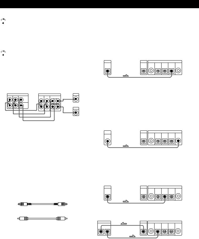
Connecting digital components
You can connect the digital output jacks of a DVD player, DAT/MD deck, CD player (etc.) to the surround processor’s digital input jacks (DIGITAL INPUT 1~4).
You can also connect the AC-3 RF output terminal of an LD player to the surround processor’s AC-3 RF INPUT terminal.
You can connect the surround processor’s digital output jack (DIGITAL OUTPUT) to a DAT/MD deck.
What cords will I need?
•Optical digital connecting cord (not supplied)
•Coaxial digital connecting cord (not supplied)
Hookups
The arrow •indicates signal flow.
DVD player
Be sure to connect the DVD player’s digital output to one of the surround processor’s DIGITAL INPUT 1~4 jacks.
DVD player |
Surround processor |
|
|||
DIGITAL |
OUTPUT |
|
INPUT |
|
|
|
DIGITAL DIGITAL |
DIGITAL |
DIGITAL |
DIGITAL |
AC-3 |
|
4 |
3 |
2 |
1 |
RF |
OUT |
|
|
|
|
|
If your DVD player has a COAXIAL DIGITAL OUTPUT, we recommend connecting the DVD player’s COAXIAL DIGITAL INPUT to the this unit’s DIGITAL INPUT 4 (COAXIAL IN) instead of making the optical connection shown above.
LD player
Be sure to connect the LD player’s AC-3 RF output to the surround processor’s AC-3 RF INPUT jacks.
LD player |
|
Surround processor |
|
|||
AC-3 |
OUTPUT |
|
|
INPUT |
|
|
RF |
DIGITAL |
DIGITAL |
DIGITAL |
DIGITAL |
DIGITAL |
AC-3 |
|
||||||
|
|
4 |
3 |
2 |
1 |
RF |
OUT |
|
|
|
|
|
|
If your LD player has an optical digital output, connect it to one of the DIGITAL INPUT 1~3 jacks on this unit.
This connection can be used together with the AC-3 RF connection.
CD player
CD player |
|
Surround processor |
|
|||
DIGITAL |
OUTPUT |
|
|
INPUT |
|
|
|
DIGITAL |
DIGITAL |
DIGITAL |
DIGITAL |
DIGITAL |
AC-3 |
|
|
4 |
3 |
2 |
1 |
RF |
OUT |
|
|
|
|
|
|
DAT/MD deck
DAT/MD deck |
|
Surround processor |
|
|||
DIGITAL |
OUTPUT |
|
|
INPUT |
|
|
|
DIGITAL |
DIGITAL |
DIGITAL |
DIGITAL |
DIGITAL |
AC-3 |
|
|
4 |
3 |
2 |
1 |
RF |
IN OUT |
|
|
|
|
|
|
Note
This unit is only compatible with digital components using 32 kHz/44.1 kHz/48 kHz sampling frequencies. It is not compatible with 96 kHz.
6EN
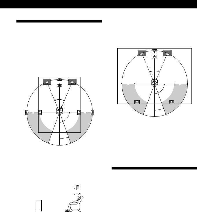
Speaker Placement
For the best possible surround sound all speakers should be the same distance from the listening position (A).
(However, this unit lets you to place the center speaker up to 1.5 meters closer (B) and the rear speakers up to 4.5 meters closer (C) to the listening position.
The front speakers can be placed from 1.0 to 12.0 meters from the listening position (A).)
B |
AA
45°
C |
C |
90°
20°
Notes
•Do not place the center or rear speakers farther away from the listening position than the front speakers.
•When mounting the rear speakers on side walls perpendicular to the listening position they should be placed 60 - 90 cm above the listening position.
Rear speaker
60 - 90 cm 

Front speaker
Getting Started
Depending on the shape of your room (etc.), you may wish to place the rear speakers behind you instead of on the side walls. One advantage of this placement is that you can use a pair of large floor standing speakers matching your front speakers.
B |
AA
45°
C |
C |
90°
20°
Note
If you place the rear speakers behind you, be sure to check the speaker location setting in the SP. SETUP menu when using VIRTUAL MULTI REAR and VIRTUAL REAR SHIFT sound fields (see pages 8 and 13 for details).
Before You Use Your Processor
If your processor has a voltage selector on the rear panel
Your processor operates on either 110-120 V or 220-230 V AC. Before connecting the unit to a wall outlet, be sure to set the voltage selector on the rear of the unit to the appropriate position according to your local power supply.
Before you start using your processor, make sure that you have:
•Turned MASTER VOLUME to –20 dB (near the center position).
Turn on the processor and check the following indicator.
•Press MUTING on the remote if “MUTING ON” appears in the display.
•Press BYPASS or one of the INPUT buttons if “BYPASS ON” appears in the display.
•Press SET UP to register the type of speakers you have connected and their distance from your listening position (see “Speaker Set Up” on the following page).
7EN
Getting Started
Speaker Set Up
To obtain the best possible surround sound, first specify the type of speakers you have connected and their distance from your listening position. Then use the test tone to adjust the speaker volumes to the same level.
Specifying the speaker type and distance
POWER |
|
|
|
|
|
|
|
|
|
|
|
|
|
|
|
|
|
|
|
SET UP |
|||||||||||||||||
|
|
|
|
|
|
|
|
|
|
|
|
|
|
|
|
|
|
|
|
|
|
|
|
|
|
|
|
|
|
|
|
|
|
|
|
|
|
|
|
|
|
|
|
|
|
|
|
|
|
|
|
|
|
|
|
|
|
|
|
|
|
|
|
|
|
|
|
|
|
|
|
|
|
|
|
|
|
|
|
|
|
|
|
|
|
|
|
|
|
|
|
|
|
|
|
|
|
|
|
|
|
|
|
|
|
|
|
|
|
|
|
|
|
|
|
|
|
|
|
|
|
|
|
|
|
|
|
|
|
|
|
|
|
|
|
|
|
|
|
|
|
|
|
|
|
|
|
|
|
|
|
|
|
|
|
|
|
|
|
|
|
|
|
|
|
|
|
|
|
|
|
|
|
|
|
|
|
|
|
|
|
|
|
|
|
|
|
|
|
|
|
|
|
|
|
|
|
|
|
|
|
|
|
|
|
|
|
|
|
|
|
|
|
|
|
|
|
|
|
|
|
|
|
|
|
|
|
+/–
1Press POWER on the front panel to turn on the processor.
2Press SET UP.
“SP.SETUP” appears in the display
3Press SET UP repeatedly to select the parameter you want to adjust.
4Turn the +/– knob to select the setting you desire. The settings is entered automatically.
5Repeat steps 3 and 4 until you have set all of the parameters shown below.
6Press SET UP to exit the set up mode.
Front speaker size
Initial setting is : FRONT SP [LARGE]
•If you connect large speakers that will effectively reproduce bass frequencies, select “LARGE”.
•If you connect small speakers with minimal bass response, select “SMALL” to activate the Dolby Digital (AC-3) bass redirection circuitry and output the front channel bass frequencies from the sub woofer or other “LARGE” speakers.
Center speaker size
Initial setting is : CENTER SP [LARGE]
•If you connect large speakers that will effectively reproduce bass frequencies, select “LARGE” (WIDE mode).
•If you connect small speakers with minimal bass response, select “SMALL” to activate the Dolby Digital (AC-3) bass redirection circuitry and output the center channel bass frequencies from the front speakers, sub woofer or other “LARGE” speakers (NORMAL mode).
•If you do not connect the center speaker, select “NO” (PHANTOM mode).
Rear speaker size
Initial setting is : REAR SP [LARGE]
•If you connect large speakers that will effectively reproduce bass frequencies, select “LARGE”.
•If you connect small speakers with minimal bass response, select “SMALL” to activate the Dolby Digital (AC-3) bass redirection circuitry and output the rear channel bass frequencies from the sub woofer or other “LARGE” speakers.
•If you do not connect rear speakers, select “NO” (3 CH mode).
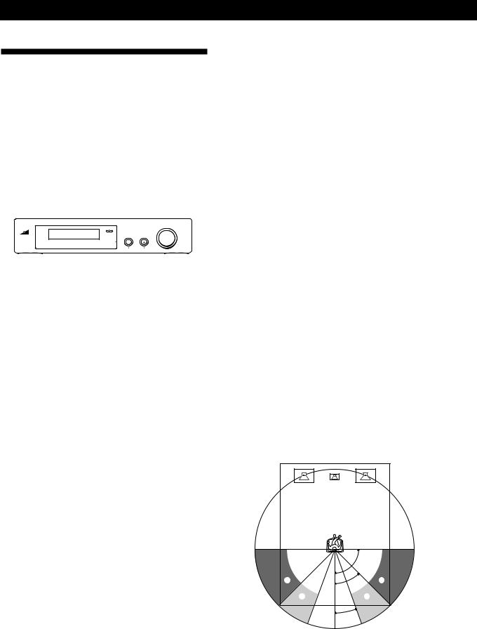
Rear speaker position
Initial setting is : REAR SP [ SIDE ]
This parameter lets you specify the location of your rear speakers for proper implementation of the Digital Cinema Sound VIRTUAL REAR SHIFT and VIRTUAL MULTI REAR modes. Refer to the illustration below.
•Set to SIDE if the location of your rear speakers corresponds to section A.
•Set to BEHIND if the location of your rear speakers corresponds to section B.
This setting effects only the VIRTUAL REAR SHIFT and VIRTUAL MULTI REAR modes.
|
90° |
A |
A |
|
45° |
B |
B |
|
20° |
8EN
Sub woofer selection
Initial setting is : SUB WOOFER [YES]
•If you connect a sub woofer, select “YES” to output the LFE (low frequency extension) channel from the sub woofer.
•If you do not connect a sub woofer, select “NO”. This activates the Dolby Digital (AC-3) bass redirection circuitry and outputs the LFE signals from other speakers.
•In order to take full advantage of the Dolby Digital (AC-3) bass redirection circuitry, we recommend setting the sub woofer’s cut off frequency as high as possible. (However, when using an amplifier with 5.1 ch inputs, set the sub woofer’s cut off frequency to match the characteristics of the amplifier.
Front speaker distance
Initial setting is : FRONT 5.0 meter/16 feet *
Set the distance from your listening position to the front (left or right) speaker (A on page 7).
•Front speaker distance can be set in 0.1 meter steps from 1.0 to 12.0 meters.
•If both speakers are not placed an equal distance from your listening position, set the distance to the closest speaker.
Center speaker distance
Initial setting is : CENTER 5.0 meter/16 feet *
Set the distance from your listening position to the center speaker.
•Center speaker distance can be set in 0.1 meter steps from a distance equal to the front speaker distance (A on page 7) to a distance 1.5 meters closer to your listening position (B on page 7).
•Do not place the center speaker farther away from your listening position than the front speakers.
Rear speaker distance
Initial setting is : REAR 3.5 meter/11 feet *
Set the distance from your listening position to the rear (left or right) speaker.
•Rear speaker distance can be set in 0.1 meter steps from a distance equal to the front speaker distance (A on page 7) to a distance 4.5 meters closer to your listening position (C on page 7).
•Do not place the rear speakers farther away from your listening position than the front speakers.
•If both speakers are not placed an equal distance from your listening position, set the distance to the closest speaker.

 To manually adjust the bass roll off frequency for each channel.
When the front, center, or rear speaker sizes are set to small, the bass roll off frequency is automatically set to 120 Hz. To select a different roll off frequency, set the menu mode to EXPAND and use the front, center, or rear speaker roll off parameters in the speaker set up menu.
For details about the menu mode, see page 15.
For details about the roll off parameters, see page 19.
Getting Started
*USA and Canadian models only
You can switch the units (meter~feet) by using the distance unit parameter in the CUSTOMIZE menu. For details about the menu mode, see page 15.
For details about the distance unit parameter, see page 17.
Adjusting the speaker volume
Use the remote while seated in your listening position to adjust the volume of each speaker.
2 A

 1, 3
1, 3
2 B 

 2 C
2 C 


 2 D
2 D 

 MASTER
VOLUME
Note
This unit incorporates a new test tone with a frequency centered at 800 Hz for easier speaker volume adjustment.
1Press TEST.
You will hear the test tone from each speaker in sequence.
2From your listening position, use the remote to adjust the volume of each speaker so that the test tone can be heard at the same level from all speakers.
APress FRONT BAL L or R to adjust the balance between the front left and right speakers (±8 dB, 0.5 dB/steps).
During this adjustment, the test tone is emitted from both speakers simultaneously.
BPress REAR BAL L or R to adjust the balance between the rear left and right speakers (±8 dB,
0.5 dB/steps).
During this adjustment, the test tone is emitted from both speakers simultaneously.
CPress CENTER + or – to adjust the level of center speaker (0.5 dB/steps).
During this adjustment, the test tone is emitted from the center speaker.
DPress REAR + or – to adjust the level of rear speakers (0.5 dB/steps).
During this adjustment, the test tone is emitted from both speakers simultaneously.
3 Press TEST to turn off the test tone.
(continued)
9EN

Getting Started

 To adjust the volume of all the speakers at one time.
Use MASTER VOLUME on the processor, remote, or your multichannel processor.
When using an amplifier with 5.1 ch inputs, Set this unit’s MASTER VOLUME to –20 dB (near the center position) and adjust the amplifier’s volume control.

 To set the test tone to a specific channel.
Set the menu mode to EXPAND and use the test tone parameter in the LEVEL ADJUST menu to select the channel you desire.
For details about the menu mode, see page 15.
For details about the test tone parameter, see page 15.
Notes
•The front balance, rear balance, center level, and rear level are shown in the display during adjustment.
•Although these adjustments can also be made with the LEVEL ADJUST menu using the knobs on the front panel, we recommend you follow the procedure described above and adjust the speaker levels from your listening position using the remote control.
10EN
|
|
|
|
Processor Operations |
Processor Operations |
|
|
|
Selecting a Component
To listen to or watch a connected component, first select the function on the processor or with the remote. Before you begin, make sure you have:
•Connected all components securely and correctly as indicated on pages 4 to 7.
•Turned MASTER VOLUME to –20 dB (near the center position) (when using an amplifier with 5.1 ch inputs).
•Turned MASTER VOLUME to –∞ dB (when using separate amplifiers for each speaker).
POWER |
|
|
INPUT buttons |
|
MASTER VOLUME |
||||||||||||||||||||||
|
|
|
|
|
|
|
|
|
|
|
|
|
|
|
|
|
|
|
|
|
|
|
|
|
|
|
|
|
|
|
|
|
|
|
|
|
|
|
|
|
|
|
|
|
|
|
|
|
|
|
|
|
|
|
|
|
|
|
|
|
|
|
|
|
|
|
|
|
|
|
|
|
|
|
|
|
|
|
|
|
|
|
|
|
|
|
|
|
|
|
|
|
|
|
|
|
|
|
|
|
|
|
|
|
|
|
|
|
|
|
|
|
|
|
|
|
|
|
|
|
|
|
|
|
|
|
|
|
|
|
|
|
|
|
|
|
|
|
|
1 Press POWER to turn on the processor.
3When connected to an amplifier with 5.1 ch inputs, turn on your amplifier, select the respective component, then select the 5.1 channel input.
EXAMPLE: Turn FUNCTION to select “LD”, then press 5.1 INPUT (for Sony TA-VA8ES). At this time, set the MASTER VOLUME control on your amplifier to “0”.
4Turn on the source component, the LD player for example, and start playback.
5Use the MASTER VOLUME on your amplifier to adjust the volume.
To |
Do this |
||
|
|
|
|
Mute the sound |
Press MUTING on the remote. |
||
|
|
Press again to restore the sound |
|
|
|
|
|
Reinforce the bass |
Press BASS BOOST to turn on the |
||
|
|
B.BOOST indicator. |
|
|
|
|
|
Turn off the display |
Press DISPLAY on the remote. |
||
|
|
|
|
Adjust the level of the |
Press the SUB WOOFER +/– on the |
||
sub woofer* |
remote. |
||
2Press an INPUT button to select the component you want to use:
To listen to or watch |
Press |
|
|
An LD player connected to the |
AC-3 RF |
AC-3 RF INPUT jack |
|
|
|
The component connected to the |
DIGITAL 1, 2, or 3 |
DIGITAL 1, 2, or 3 optical input |
|
jack.* |
|
|
|
The component connected to the |
DIGITAL 4 |
DIGITAL 4 coaxial input jack. |
|
|
|
The component connected to the |
BYPASS** |
BYPASS input jacks. |
|
|
|
*This unit’s digital inputs detect Dolby Digital (AC-3) or PCM signals automatically. (The AC-3 RF input terminal for use with LD players is for Dolby Digital (AC-3) signals only.)
**• The menu functions may not be available when the unit is set to the “BYPASS ON” mode.
•If you connected an additional audio amplifier (etc.) to the BYPASS IN jacks on the processor as described on page 6, use the function selector on that component to select the component you want to listen to (“CD” for example).
•This unit switches to the “BYPASS ON” mode while its POWER is set to off.
*In order to take full advantage of the Dolby Digital (AC-3) bass redirection circuitry, we recommend setting the sub woofer’s cut off frequency as high as possible. (However, when using an amplifier with 5.1 ch inputs, set the sub woofer’s cut off frequency to match the characteristics of the amplifier.)
Using the remote
The remote lets you operate the processor.
EXAMPLE: To listen to a Dolby Digital (AC-3) encoded Laserdisc played back in
INPUT SELECT </> 


 BYPASS
1Press POWER on the front panel to turn on the processor.
2Press INPUT SELECT < or > repeatedly to display the input for the component you want to use (or press BYPASS to display “BYPASS ON”).
EXAMPLE: If you connected your LD player to the AC-3 RF INPUT, select “AC-3 RF”.
11EN

Processor Operations
Selecting a Surround Field
You can select a surround field according to the type of source you are playing.
When playing program sources recorded in the Dolby Digital (AC-3) format, you can enjoy surround sound simply by selecting “DOLBY SURROUND”.
This unit also incorporates several pre-programmed sound modes called “Digital Cinema Sound”. Select from these surround modes according to your preference to enjoy powerful surround effects from a wide variety of program sources.
DOLBY SURR |
MODE |
OFF |
MODE
DOLBY 

 OFF
OFF
SURROUND
To select the Dolby Surround mode
Press DOLBY SURR(OUND).
Normally, select this mode when playing program sources recorded in the Dolby Digital (AC-3) format.
To select Digital Cinema Sound
Press MODE repeatedly until the mode you desire appears in the display.
See the chart on the following page for details regarding the types of surround modes available and the effects they provide.

 When you select DOLBY SURROUND.
When the signal being input is PCM, normal 2 channel playback occurs.
When the signal being input is Dolby Digital (AC-3), the number of channels played back are determined automatically according to the characteristics of the input signal.
In the “DOLBY SURROUND” mode the number of channels being played back from the current program source appear in the display as shown below:
Display |
Channels played back |
STEREO PCM [xx kHz]* |
Normal PCM playback |
DOLBY DIGITAL [1/0]** |
Center only (mono) |
DOLBY DIGITAL [2/0] |
Front (L, R) |
DOLBY DIGITAL [2/1] |
Front (L, R) + Rear (mono) |
|
|
DOLBY DIGITAL [2/2] |
Front (L, R) + Rear (L, R) |
DOLBY DIGITAL [3/0]** |
Front (L, R) + Center |
DOLBY DIGITAL [3/1] |
Front (L, R) + Center + |
|
Rear (mono) |
DOLBY DIGITAL [3/2] |
Front (L, R) + Center + |
|
Rear (L, R) |
DOLBY PROLOGIC |
Front (L, R) + Center + |
|
Rear (mono) |
*48 kHz, 44.1 kHz, or 32 kHz is displayed. 44.1 kHz is displayed as “44 kHz”.
**The surround effect may not be readily apparent in all cases.
When playing a 2 channel Dolby Digital (AC-3) source, the unit determines either Pro Logic of stereo playback automatically according to the information provided by the program source.

 You can find Dolby Surround-encoded software by looking at the packaging
Use discs with the 


 logo. In order to enjoy Dolby Digital (AC-3) playback you must use discs bearing this logo.
12EN
Processor Operations
Digital Cinema Sound
Surround |
Effect |
mode |
|
|
|
NORMAL |
Decodes programs processed with Dolby |
SURROUND |
Surround. Use to decode 2 ch sources |
|
using Dolby Pro Logic decoding. |
|
|
ENHANCED |
Provides a greater sense of presence from |
SURROUND |
Pro Logic sources with monaural rear |
|
channel sound. Produces a stereo like |
|
effect in the rear channels. |
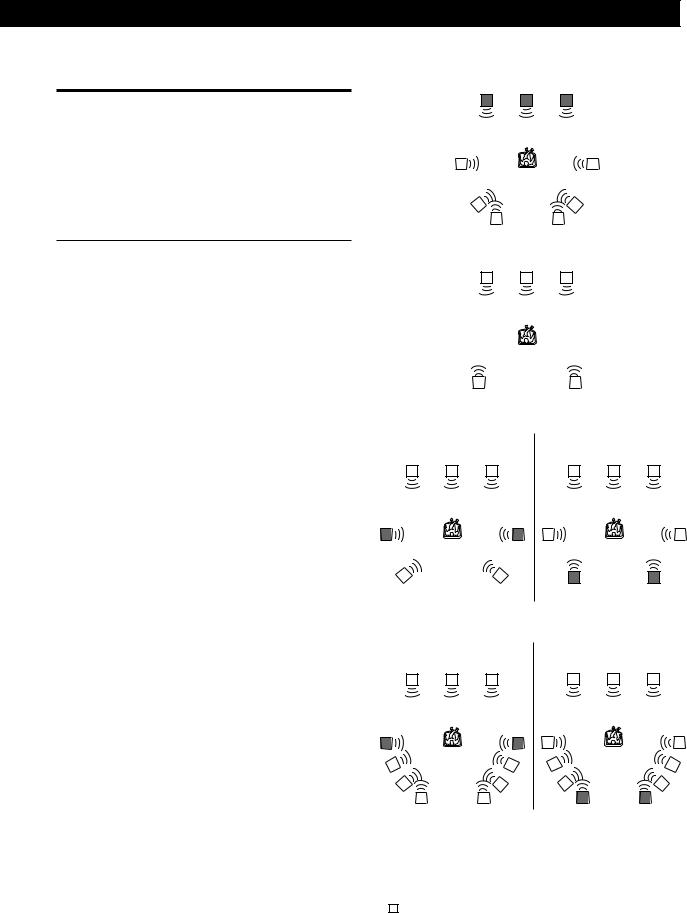
Ill.1 VIRTUAL ENHANCED (SURROUND) A
L C R
LARGE |
Use Reproduce the acoustics of a standard |
|
|
THEATER |
movie theater. |
|
|
|
|
|
|
CINEMA |
Reproduces the sound characteristics of |
|
|
STUDIO A |
the Sony Pictures Entertainment “Cary |
|
|
|
|
Grant Theater” cinema production studio. |
|
|
|
|
|
CINEMA |
Reproduces the sound characteristics of |
|
|
STUDIO B |
the Sony Pictures Entertainment “Kim |
|
|
|
|
Novak Theater” cinema production studio. |
|
|
|
|
|
CINEMA |
Reproduces the sound characteristics of |
|
|
STUDIO C |
the Sony Pictures Entertainment scoring |
|
|
|
|
stage. |
|
|
|
|
|
VIRTUAL |
Uses 3D sound imaging to create virtual |
|
|
ENHANCED |
rear speakers from the sound of the front |
|
|
(SURROUND) |
speakers without using actual rear |
|
|
A (Ill.1) |
speakers. |
|
|
|
|
The virtual speakers are reproduced as |
|
|
|
shown in Ill. 1. |
|
|
|
|
|
VIRTUAL |
Uses 3D sound imaging to create virtual |
|
|
ENHANCED |
rear speakers from the sound of the front |
|
|
(SURROUND) |
speakers without using actual rear |
|
|
B (Ill.2) |
speakers. |
|
|
|
|
The virtual speakers are reproduced as |
|
|
|
shown in Ill. 2. |
|
|
|
|
|
VIRTUAL |
Uses 3D sound imaging to shift the sound |
|
|
REAR |
of the rear speakers away from the actual |
|
|
SHIFT |
speaker position. The shift position differs |
|
|
(Ill.3) |
according to the setting of the rear speaker |
|
|
|
|
position (SP. SETUP). |
|
|
|
|
|
VIRTUAL |
Uses 3D sound imaging to create an array |
|
|
MULTI |
of virtual rear speakers from a single pair |
|
|
REAR |
of actual rear speakers. The position of the |
|
|
(Ill.4) |
virtual rear speakers differs according to |
|
|
|
|
the setting of the rear speaker position (SP. |
|
|
|
SETUP). |
|
|
|
|
|
LARGE |
Reproduces the acoustics of a live house. |
|
|
HALL |
Use when playing recordings of live |
|
|
|
|
concerts (etc.). |
|
|
|
|
|
LIVE |
Create a simulated surround sound from |
|
|
HOUSE |
monaural sources such as old movies or |
|
|
|
|
TV programs. |
|
|
|
|
|
To turn off the surround effect (2 channel stereo playback)
Press OFF (or DIGITAL CINEMA SOUND - OFF on the remote). At this time Dolby Digital (AC-3) signals are automatically downmixed to front (L, R) signals.
Ill.2 VIRTUAL ENHANCED (SURROUND) B
L C R
|
|
|
|
|
|
|
|
|
|
|
|
|
|
|
|
|
|
Ill.3 VIRTUAL REAR SHIFT |
|
|
|
|
|
|
|
|
|||||||||
|
For REAR SP [SIDE]* |
For REAR SP [BEHIND]* |
|||||||||||||||
|
L |
C |
|
R |
|
|
L |
C |
|
R |
|||||||
|
|
|
|
|
|
|
|
|
|
|
|
|
|
|
|
|
|
SL |
SR |
SL SR
Ill.4 VIRTUAL MULTI REAR |
|
|
|
|
|
|
|
||||||
|
For REAR SP [SIDE]* |
For REAR SP [BEHIND]* |
|||||||||||
|
L |
C |
|
R |
|
L |
C |
|
R |
||||
|
|
|
|
|
|
|
|
|
|
|
|
|
|
SL |
SR |
|
SL |
SR |
L : Front speaker (left) |
* See page 8 for details on |
|
R : Front speaker (right) |
how to set the rear speaker |
|
C : Center speaker |
position. |
|
SL : Rear speaker (left) |
|
|
SR : Rear speaker (right) |
|
|
: Virtual speaker |
|
|
(continued)
13EN

Processor Operations
Adjusting the Surround Effect Level (for Digital Cinema Sound modes only*)
You can adjust the surround effect level. This control lets you adjust the “presence” of the current Digital Cinema Sound mode from 0% (no digital cinema sound effects) to 100%(150%) in 5% steps.
*This adjustment is not possible in the NORMAL SURROUND or ENHANCED SURROUND mode.
1Start playing a program source.
2Press DIGITAL CINEMA SOUND - MODE on the remote repeatedly to select the mode you desire.
3Press EFFECT + or – on the remote to select the level you prefer. The effect level is indicated in the display during adjustment. The level is stored automatically.
Note
Changing the effect level may not produce major variations in the surround effect when used with certain playback sources.

 You can also adjust the surround effect level using the controls on the front panel.
Use the MENU and the +/– knobs to adjust the surround effect level parameter in the SURROUND menu.
See page 15 for details on menu operations and the surround effect level parameter.
Compressing the dynamic range (Dolby Digital (AC-3) only)
When inputting a Dolby Digital (AC-3) signal you can compress the dynamic range of the sound track by using the dynamic range compression parameters in the SURROUND menu. This may be useful when you want to watch movies at low volumes late at night. See page 15 for details on menu operations and page 16 for details on the dynamic range compression parameter.
Digital Recording
This processor makes it easy to make digital recordings from the components connected to the processor. You don’t have to connect playback and recording components directly.
Before you begin, make sure you’ve connected all components properly.
INPUT buttons
|
|
• |
|
|
|
|
|
|
|
|
|
• |
|||||
|
|
|
|
|
|
|
||
|
Playback component |
|
Digital recording |
|
||||
|
(CD player, etc.) |
|
component |
|
||||
|
|
|
|
|
(DAT deck, MD |
|
||
|
|
|
|
|||||
•: Signal flow |
|
deck , etc.) |
|
|||||
|
|
|
|
|
||||
EXAMPLE: Recording a CD using a DAT deck.
See your DAT or CD player’s instruction manual if you need help.
1Press DIGITAL 1 (if a CD player is connected to the DIGITAL 1 INPUT) to select the CD player.
2Insert a blank digital audio tape into the DAT for recording.
3Start recording on the DAT and then start playing the CD you want to record.
Note
You cannot record the digital signal from a Dolby Digital (AC-3) program source.
14EN
 Loading...