


4-137-706-01(1)
HD Color Camera
Operating Instructions
Before operating the unit, please read this manual thoroughly and retain it for future reference.
HXC-100
© 2009 Sony Corporation

WARNING
To reduce the risk of fire or electric shock, do not expose this apparatus to rain or moisture.
To avoid electrical shock, do not open the cabinet. Refer servicing to qualified personnel only.
For the customers in the U.S.A.
This equipment has been tested and found to comply with the limits for a Class A digital device, pursuant to Part 15 of the FCC Rules. These limits are designed to provide reasonable protection against harmful interference when the equipment is operated in a commercial environment. This equipment generates, uses, and can radiate radio frequency energy and, if not installed and used in accordance with the instruction manual, may cause harmful interference to radio communications. Operation of this equipment in a residential area is likely to cause harmful interference in which case the user will be required to correct the interference at his own expense.
You are cautioned that any changes or modifications not expressly approved in this manual could void your authority to operate this equipment.
All interface cables used to connect peripherals must be shielded in order to comply with the limits for a digital device pursuant to Subpart B of Part 15 of FCC Rules.
For the customers in Europe
This product with the CE marking complies with both the EMC Directive and the Low Voltage Directive issued by the Commission of the European Community.
Compliance with these directives implies conformity to the following European standards:
•EN60950-1: Product Safety
•EN55103-1: Electromagnetic Interference (Emission)
•EN55103-2: Electromagnetic Susceptibility (Immunity) This product is intended for use in the following Electromagnetic Environments:
E1 (residential), E2 (commercial and light industrial), E3 (urban outdoors), E4 (controlled EMC environment, ex. TV studio).
The manufacturer of this product is Sony Corporation, 1-7-1 Konan, Minato-ku, Tokyo, Japan.
The Authorized Representative for EMC and product safety is Sony Deutschland GmbH, Hedelfinger Strasse 61, 70327 Stuttgart, Germany. For any service or guarantee matters please refer to the addresses given in separate service or guarantee documents.
For the State of California, USA only
Perchlorate Material - special handling may apply, See www.dtsc.ca.gov/hazardouswaste/perchlorate Perchlorate Material : Lithium battery contains perchlorate.
For the customers in Taiwan only
Table of Contents |
|
Overview ................................................................... |
3 |
Features .......................................................................... |
3 |
System Configuration ...................................................... |
4 |
Standalone operation example .................................. |
4 |
System operation example (with a Camera Control |
|
Unit) ....................................................................... |
5 |
Parts Identification ........................................................... |
5 |
Front right .................................................................. |
5 |
Front left .................................................................... |
6 |
Rear ........................................................................... |
7 |
Operation panel ......................................................... |
7 |
Connector panel ........................................................ |
8 |
Installation ................................................................ |
9 |
Connecting a Camera Control Unit (CCU) ...................... |
9 |
Attaching a Lens ........................................................... |
10 |
Attaching a Viewfinder .................................................. |
10 |
Attaching a Microphone ................................................ |
11 |
Mounting the Camera to a Tripod ................................. |
12 |
Adjusting the Shoulder Pad Position ............................. |
13 |
Preparatory Settings.............................................. |
13 |
Adjusting the Black Balance and White Balance .......... |
13 |
Setting the Electronic Shutter ........................................ |
14 |
Setting the Local Time .................................................. |
15 |
Adjusting the Flange Focal Length ................................ |
15 |
Setting the Focus Assist Function ................................. |
16 |
Setting the Camera Outputs .......................................... |
17 |
Outputting a Trunk Signal ............................................. |
18 |
Basic Procedure for Shooting............................... |
19 |
Menus...................................................................... |
20 |
Displaying Menu Pages ................................................ |
20 |
Setting the Menu ........................................................... |
20 |
Editing the USER Menu ................................................ |
21 |
OPERATION Menu ....................................................... |
24 |
PAINT Menu .................................................................. |
28 |
MAINTENANCE Menu .................................................. |
30 |
FILE Menu ..................................................................... |
32 |
DIAGNOSIS Menu ........................................................ |
34 |
Appendices............................................................. |
34 |
Precautions ................................................................... |
34 |
Error Messages ............................................................. |
35 |
Using a “Memory Stick” ................................................. |
35 |
Specifications ................................................................ |
36 |
Menu Tree ..................................................................... |
38 |
2 |
Table of Contents |
|
|

Overview
The HXC-100 is a 2/3-type high-definition portable video camera equipped with CCD units for 2,200,000 pixels, which can be used as a standalone camera as well as in a studio in combination with the HXCU-100 Camera Control Unit.
The camera incorporates the latest image capturing device and digital signal-processing LSI, and it performs newly developed digital transmission with the camera control unit (CCU), thus yielding high picture quality and high stability in image creation in addition to superior camera functions and operability.
Features
High picture quality and high performance
The latest 2/3-type Progressive IT CCD units for 2,200,000 pixel achieve high sensitivity and low smear. In addition, the 14-bit A/D converter and an original developed signalprocessing LSI provide high picture quality of optimal grade.
Multiple formats
The camera covers 1080/59.94i, 720/59.94P, 1080/50i, and 720/50P.
With its wide-range down-converter, the camera also enables output of high-quality SD signals (525i/625i) from the camera and the connected CCU, establishing an optimum camera system for SD-system operations.
Newly designed integrated unit with low center of gravity
The camera has stylish appearance with low-slung design. Even when used in combination with a studio-use viewfinder, stable operation is achieved, thanks to its low center of gravity.
Optimized handle shape and VF slide mechanism for stable shooting
A new handle design has been adopted. A slight protrusion of the upper front part of the handle enables stable holding of the camera while you are shooting, by holding the front part of the handle. Furthermore, a slide mechanism is located at the viewfinder attachment position. Any difference in weight balance caused by having a different lens attached can be counteracted by adjusting the viewfinder attachment position, in combination with the movable shoulder pad position. This provides the best balance for shooting with the camera on your shoulder.
Position-adjustable shoulder pad
The position of the shoulder pad can be adjusted for stable shooting according to the build of the camera operator, the type of lens in use, or the shooting style.
A low-repulsion shoulder pad (position fixed) is available as an option. (Part No.: A-8286-346-A)
Function-assignable switches
The camera has buttons to which various functions can be assigned on the side panel and the rear. You can activate your desired function, such as electronic color-temperature conversion, instantly when shooting by assigning it to one of these buttons in advance.
Buttons on the handle are also available as function assignable switches.
Auto Lens Aberration Compensation function
The Auto Lens Aberration Compensation function (ALAC) is provided with this camera. This automatically reduces chromatic aberration of magnification when a lens that supports auto aberration compensation is attached.
For details on lenses supporting auto aberration compensation, contact a Sony sales representative or Sony service representative.
Focus assist functions
The VF detail function and focus assist indicator function facilitate focusing.
VF detail
Various functions are provided for the VF detail signal, which can be added only on images on the viewfinder screen in order to facilitate focusing in various situations: Functions for coloring the VF detail signal, flickering the VF detail signal by adding modulation, thickening the VF detail signal, and automatically compensating the VF detail level according to the zoom position.
Focus Assist Indicator
The focusing level indicator on the viewfinder screen provides a guide for focusing. The best focus setting can be easily determined by observing fluctuation of the level indicator as a guide.
“Memory Stick” 1) operation
The camera is equipped with a “Memory Stick” port, which enables setup data storage and software upgrading using a “Memory Stick.”
1)“Memory Stick” and 


 are trademarks of Sony Corporation.
Various color-reproduction functions
Selection of multiple gamma tables
Seven types of standard and 4 types of hyper gamma tables are provided with this camera. The hyper gamma values enable cinemalike image creations with wide dynamic range, which are different from those achieved with conventional video gamma.
Multimatrix color correction
In addition to the standard 6-axis matrix function, the camera has a multimatrix function that permits you to adjust the hue and chroma for color components in 16-axis directions independently. This is quite useful in color matching among multiple cameras.
Overview 3

Knee saturation
Change of hue and decrease in chroma that occur in highlighted areas can be compensated.
This enables reproduction of natural skin tones under strong lighting.
Low key saturation
Hue and chroma in low-key zones can be compensated. Thus, compensation for color reproduction in all zones is enabled in combination with matrix color compensation and knee saturation functions.
Versatile detail control functions
Skin-tone detail function
This function allows control (emphasis or suppression) of the detail level for just a certain hue or chroma area in the image, by creating a detail gate signal from color components of your specified hue, such as skin tones.
Detail boost-frequency control
The boost frequency can be adjusted from 20 to 30 MHz. This allows the detail thickness to be set appropriately for the subject, thus enabling more subtle image expression.
H/V ratio control
The ratio between horizontal and vertical detail can be adjusted.
White/black limiter
The white and black details can be limited independently.
Easy menu-based setting
Selections and settings for viewfinder display items, safetyzone marker 1) or center marker,2) screen size marker, etc. can be made quickly and easily, using setup menus displayed on the viewfinder screen or an external monitor.
1)Safety zone marker: A box-shaped marker displayed on the viewfinder screen which indicates 80%, 90%, 92.5%, or 95% of the total screen area
2)Center marker: A cross-shaped marker which indicates the center of the viewfinder screen
Wide variety of viewfinder display options
Along with items such as operation messages, a zebra pattern,1) a safety-zone marker, and a center marker, camera settings may also be displayed on the viewfinder screen. Furthermore, there are various cautionary and warning indications to be occasionally displayed, making it simple to check the status of the camera.
1)Zebra pattern: A stripe pattern displayed on the viewfinder screen which indicates the portions where the video level is above about 70% or 100%. Used to check the video level of the subject.
Digital triax transmission
The camera uses an industry standard dual-shield coaxial (triax) camera cable for connection between the camera and a CCU. Newly developed original digital transmission technology is built into the camera, and high-quality pictures can be transmitted between the camera and CCU, regardless of the cable length.
Versatile choices of viewfinders
Multiformat monochrome CRT viewfinders, HDVF-200 (2- type) and HDVF-550 (5-type) can be selected for use in studio and portable systems.
Color LCD viewfinders, HDVF-C35W (3.5-type), HDVFC730W (6.3-type), and HDVF-C950W (9-type), are also selectable to cover various applications.
Prevention of electrical shock
When the power connection is unsafe, the power supply from the connected Camera Control Unit will be shut off.
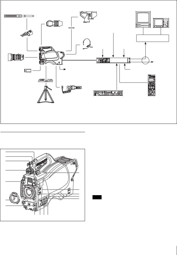
System Configuration
Peripherals and related devices for the camera are shown in figures.
Note
Production of some of the peripherals and related devices shown in the figures has been discontinued. For advice on choosing devices, please contact your Sony dealer or a Sony sales representative.
Standalone operation example
Microphone
HDVF-200/C35W Viewfinder
CAC-12 Microphone  holder
Zoom Lens
(for ENG/EFP)
“Memory Stick”
VCT-U14
Tripod Adaptor
Tripod for portable camera
HXC-100 Video output HD-SDI/SD-SDI/VBS1) (selectable)
|
AC adaptor |
|
AN-DN10/DN2B |
CCA-5 cable |
BC-L70/L160 |
AC power |
RCP-700/900-series |
RM-B750/B150 |
|
Remote Control Panel |
||
Remote Control Unit |
||
|
1)No subcarrier phase-lock function with respect to external reference is available for the VBS signal output from the camera.
4 Overview
System operation example (with a Camera Control Unit)
Microphone
CAC-12
Microphone
Holder
Zoom Lens
(for ENG/EFP)
“Memory Stick”
VCT-U14
Tripod Adaptor
Tripod for portable camera
HDVF-550/C730W/C950W |
|
Picture |
|
|
Viewfinder |
|
Monitor |
|
|
|
|
|
|
|
HDVF-200/C35W |
|
|
|
Waveform |
|
|
|
Monitor |
|
Viewfinder |
|
|
|
|
VF attachment shoe a) |
|
BNC |
BNC |
|
|
Return video input |
|||
Intercom headset |
|
Video router |
||
|
|
|
||
HXC-100 |
Sync input |
Prompter video input |
|
|
|
|
|||
|
|
|
Video output |
|
Triax cable b) |
|
|
HD-SDI/SD-SDI/VBS |
|
|
|
|
|
|
|
|
|
|
to router/switcher |
Power supply |
HXCU-100 |
|
AC power |
|
for a script light |
Camera Control |
|
|
|
DC 12 V |
Unit |
|
|
|
(Max. 0.5 A) |
|
|
|
|
|
|
CCA-5 cable |
|
|
|
(attached to the front) |
|
|
|
CAC-6 |
HKCU-FP1 |
|
RCP-700/900-series |
|
Return Video Selector |
|
|||
|
Front Control Panel |
Remote Control Panel |
||
a)Supplied with the HDVF-550/C730W/C950W, Part No.: A-7612-405-E
b)600 m (1969 ft) at maximum and 50 m (164 ft) at minimum when using Fujikura 8.5-mm dia. cables.
For information of other cables, see “About the distances of triax transmission” (page 35).
Parts Identification
Front right
1 |
|
2 |
|
3 |
|
4 |
8 |
|
|
5 |
|
|
9 |
|
0 |
|
qa |
6 |
qs |
|
|
7 |
|
qh |
qg qf qd |
aINCOM (intercom) button (UC model)/ENG (engineer line) button (CE model)
UC model: The intercom microphone is on while this button is held pressed.
CE model: The intercom microphone is on and the engineer line is selected while this button is held pressed.
You can also assign other functions with a menu operation.
b RET 1 (return video 1) button
The return video 1 signal from the CCU is monitored on the viewfinder screen while this button is held pressed. It functions the same as the RET 1 button on the operation panel (page 7) on the rear of the camera.
You can also assign other functions with a menu operation.
c Accessory shoe
To attach an accessory using a 1/4-inch screw.
Note
When you wish to replace it with a slide-type shoe, consult Sony service personnel.
d Viewfinder shoe
Mount a viewfinder.
For details, see “Attaching a Viewfinder” (page 10).
e Lens cable clamp
To secure the cable of the lens (optional).
Overview 5

f Lens mount cap
The cap can be removed by moving the lens fixing lever upward. Always keep the lens mount covered with this cap when a lens is not attached.
g Lens fixing lever
Move the lever down to secure the lens in the lens mount.
For details, see “Attaching a Lens” (page 10).
h Viewfinder front-rear position lock lever
The viewfinder position can be adjusted forward or backward when the lock is released by the lever.
For details on the adjustment, see “To adjust the viewfinder’s front-rear position” (page 10).
i Assignable buttons
You can assign a function to the upper button by using ASSIGNABLE 1 and the lower button with ASSIGNABLE 2 on the <SWITCH ASSIGN1> page of the OPERATION menu.
j GAIN switch
To select the gain of the video amplifier based on lighting conditions when the camera is used in standalone status without connecting a CCU.
When shipped from the factory, the values set are L = 0 dB, M = 6 dB, and H = 12 dB.
k AUTO KNEE and output signal selection switch
To select the signal (color-bar signal or camera’s video signal) to be used as output to a VTR, the viewfinder, or a video monitor when the camera is used in standalone status without connecting a CCU.
When the camera’s video signal is being used as output, the auto knee function can be selected.
BARS/OFF: Output is a color-bar signal.
CAM/OFF: Output is the camera’s video signal. The auto knee circuit is disabled.
CAM/ON: Output is the camera’s video signal. The auto knee circuit is enabled.
l WHITE BAL (white balance memory selection) switch
To select the white balance adjustment method or the memory used to store the adjusted value when the camera is used in standalone status without connecting a CCU.
PRST (preset): White balance is adjusted to a preset value corresponding to a color temperature of 3200K.
A:To select memory A.
B:To select memory B.
Note
When a CCU or an external control device, such as an RCP/ RM, is connected, the functions of 0 to qs are controlled from the external device or the HKCU-FP1 attached to the CCU, and the controls on the camera are disabled.
m DISPLAY/MENU switch
Select the display on the viewfinder screen.
DISPLAY: To display various textual information and markers, such as messages showing the camera settings and operating status, the center marker, and the safety zone marker, in addition to camera images.
OFF: To not display textual information and markers. MENU: To display menus for camera settings.
The switch functions the same as the DISPLAY/MENU switch on the rear operation panel.
n “Memory Stick” slot and access lamp
When you insert a “Memory Stick” into the slot, the access lamp lights in green.
The lamp is lit in red while writing/reading data to/from the “Memory Stick.”
Note
When the access lamp is lit in red, do not insert/remove the “Memory Stick” or turn off the camera.
o STATUS/CANCEL switch
STATUS: To display status information of this camera in the viewfinder when no menu is displayed with the DISPLAY/ MENU switch set to DISPLAY.
CANCEL: To cancel changed settings or return the display to the previous menu when a menu is displayed in the viewfinder.
p Menu control knob (rotary encoder)
Used to select settings from menus displayed on the viewfinder screen (by rotating it) and to confirm settings (by pushing it).
This knob functions the same as that on the rear operation panel.
Front left
|
1 |
|
2 |
|
3 |
|
4 |
|
5 |
|
6 |
0 |
7 |
9 |
8 |
a Shoulder strap fitting post
Attach one end of a shoulder strap (optional, part No. A-6772- 374-C) to this fitting post and the other end to the fitting post on the other side of the camera.
b VF (viewfinder) connector (20-pin)
Connect the cable of the viewfinder (optional).
c Filter select knob
Used to select the built-in ND filters (1: clear, 2: 1/4 ND, 3: 1/16 ND, 4: 1/64 ND).
d SHUTTER switch
When the camera is used in standalone status without connecting a CCU, use this switch to turn ON or OFF the electronic shutter and change (SEL) the shutter speed and shutter mode.
For details, see “Setting the Electronic Shutter” (page 14).
6 Overview

e AUTO W/B BAL (white and black balance automatic adjustment) switch
To automatically adjust white and black balance when the camera is used in stand-alone status without connecting to a CCU.
WHT: To automatically adjust white balance. BLK: To automatically adjust black balance.
For details, see “Adjusting the Black Balance and White Balance” (page 13).
f INTERCOM LEVEL control
To adjust the intercom/earphone volume level.
The intercom level adjustment is enabled when the LEVEL/ MIC switch on the UC-type operation panel (page 7) or the LEVEL switch on the CE-type operation panel (page 8) on the rear is set to “FRONT.”
g RET (return video) button
When this button is pressed, the picture on the viewfinder changes to the return video signal selected with the RET 2/3/ 4 select switch (page 7) on the operation panel on the rear of the camera.
You can also assign other functions with a menu operation.
h LENS connector (12-pin)
Connect the lens cable. The camera can control the lens functions through this cable.
i MIC 1 IN (microphone 1 input) connector (XLR 3-pin)
Connect a microphone.
This connector and the AUDIO IN CH1 connector are alternately activated with the MIC 1 select switch on the rear connector panel.
j Tripod mount (bottom)
Attach the VCT-U14 Tripod Adaptor when mounting the camera on a tripod.
For details, see “Mounting the Camera to a Tripod” (page 12).
Rear |
1 |
2 |
3 |
4 |
5 |
6 |
7 |
0 |
9 8 |
a Tally lamp and switch
ON: The tally lamp lights when a tally signal is input to the connected CCU or a call signal is generated in response to pressing of a CALL button.
OFF: The tally lamp is prevented from lighting.
b Shoulder strap fitting post
c Operation panel (See “Operation panel”.)
d Camera Control Unit (CCU) connector (triax connector)
Connect an HXCU-100 Camera Control Unit using a triax cable.
e INTERCOM connector (XLR 5-pin)
Connect an XLR 5-pin headset for input and output of intercom audio signals.
The connector can be used for communication over the engineer line when the camera is in standby status.
f EARPHONE jack (stereo minijack)
For connecting an earphone for output of the intercom audio.
g Connector panel (See “Connector panel” on page 8.)
h CAMERA POWER switch and indicator
CCU: To operate on power supply via the connected CCU. EXT: To operate on power supply through the DC IN
connector.
The indicator is lit in green during operation. It is lit in red while standby power is being supplied from the CCU, even if the switch is set to OFF.
i CALL button
When you press this button, the red tally lamp of the connected external control device (RCP/RM, HKCU-FP1, etc.) will light. Use to call the operator of the external control device.
j Shoulder pad
You can adjust the position on your shoulder.
For details, see “Adjusting the Shoulder Pad Position” (page 13).
Operation panel
UC type: Model for NTSC areas
|
|
1 |
2 |
3 4 |
5 |
|
|
RET1 |
RET |
2 3 4 |
|
|
|
PGM1 |
PGM2 |
ASSIGNABLE |
|
|
LEVEL |
MIC |
|
DISPLAY |
|
|
|
|
|
||
|
REAR |
ON |
|
OFF |
|
|
|
|
|
|
|
|
|
|
|
MENU |
|
|
FRONT |
OFF INCOM |
|
|
|
|
PROD |
|
|
|
|
|
ENG |
|
|
|
|
|
INTERCOM |
EARPHONE |
|
||
6 |
7 |
8 9 |
|
|
|
a RET 1 (return video 1) button
The return video signal is displayed on the viewfinder screen while the button is held pressed.
b RET (return video) button and 2/3/4 (return video 2/3/4) select switch
When other return video systems are used in addition to return video 1, the signal selected with the 2/3/4 switch is displayed on the viewfinder screen while holding the RET button pressed.
Overview 7
Note
The RET 1 button has priority over the RET (2/3/4) button if both buttons are pressed.
c DISPLAY/MENU switch
This switch functions the same as the DISPLAY/MENU switch on the front (page 6).
d ASSIGNABLE button
You can assign a function with ASSIGNABLE REAR on the <SWITCH ASSIGN1> page of the OPERATION menu.
e Menu control knob (rotary encoder)
This knob functions the same as the menu control knob on the front (page 6).
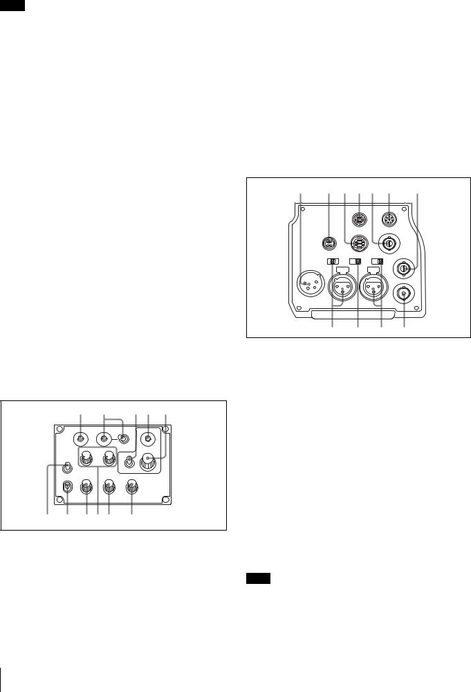
fLEVEL/MIC (intercom level control/microphone) switch
To determine whether to use the INTERCOM LEVEL control (page 7) on the front and to turn the intercom headset microphone ON/OFF.
Switch position |
INTERCOM LEVEL |
Headset microphone |
|
control on the front |
|
REAR/ON |
Inactive |
ON |
|
|
|
REAR/OFF |
|
OFF |
|
|
|
FRONT/OFF |
Active |
|
|
|
|
g Line select switch
To select the intercom line: PROD: Producer line ENG: Engineer line
h INCOM (intercom) level control
To adjust the intercom audio listening level.
i PGM1 (program 1) and PGM2 (program 2) controls
To adjust the audio listening level of program 1 or program 2, respectively.
CE type: Models for PAL areas
|
|
1 |
2 |
3 4 |
5 |
|
|
RET1 |
RET |
2 3 4 |
|
|
|
PGM1 |
PGM2 |
ASSIGNABLE |
|
|
|
|
|
DISPLAY |
|
|
MIC |
|
|
|
|
|
LINE |
PROD |
|
OFF |
|
|
|
OFF |
|
MENU |
|
|
|
ENG |
|
|
|
|
LEVEL |
|
|
|
|
|
ENG |
PROD |
TRACKER |
|
|
|
REAR |
|
|||
|
FRONT |
|
|
|
|
|
INTERCOM |
EARPHONE |
|
||
6 |
7 |
8 9 0 |
qa |
|
|
1 to 5 are the same as those of the UC type.
f MIC LINE (intercom microphone line) switch
To select the talk line for intercom: PROD: To talk over the producer line
OFF: To turn off the headset microphone for the intercom line ENG: To talk over the engineer line
g LEVEL switch
REAR: The intercom audio listening level is adjusted with the ENG or PROD control on this panel.
FRONT: The levels adjusted on the rear panel can be totally adjusted with the INTERCOM LEVEL control on the front.
h ENG (engineer line) control
To adjust the intercom audio listening level of the engineer line.
i PGM1 (program 1) and PGM2 (program 2) controls
To adjust the audio listening level of program 1 or program 2, respectively.
j PROD (producer line) control
To adjust the intercom audio listening level of the producer line.
k TRACKER control
To adjust the intercom audio listening level at the TRACKER connector on the connector panel.
Connector panel
1 |
2 |
3 4 5 |
6 |
7 |
|
|
|
RET CTRL |
|
REMOTE |
|
|
|
|
PROMPTER |
|
|
|
DC OUT |
TRACKER |
/GENLOCK |
|
|
|
|
/RET |
|
|
|
|
|
MIC1 |
LINE MIC +48V |
TEST |
|
|
LINE MIC +48V FRONT REAR |
OUT |
|||
DC IN 10.5-17V |
AUDIO IN |
|
|
|
|
|
|
CH1 |
|
CH2 |
|
|
|
|
|
|
SDI |
8 9 0 qa
a DC IN (DC power supply input) connector (XLR 4-pin)
For connection to an AC-DN10 AC Adaptor, etc. to supply power to the camera.
b DC OUT (DC power supply output) connector (4-pin)
To supply power to a script light or equivalent (12 V DC, max. 0.5 A).
c TRACKER connector (10-pin)
For external interfaces, such as intercom and tally.
d RET CTRL (return control) connector (6-pin)
For connection to a CAC-6 Return Video Selector.
ePROMPTER/GENLOCK/RET (prompter signal output/ external sync signal input/VBS return input) connector
(BNC type)
•When a CCU is connected, this connector outputs a VBS prompter signal.
•When the camera is used in standalone status without connecting a CCU, use this connector for input of an external sync signal (BB or 3-level sync). If a VBS signal is input, you can check the input image by pressing the RET button.
Note
Even when a BB signal is used for the external sync signal, no subcarrier phase-lock function is available for the VBS output signal.
8 Overview
f REMOTE connector (8-pin)
For connection to an RM-B150/B750 Remote Control Unit or RCP-700/900-series Remote Control Panel.
Note
When a CCU is used in combination, this connector functions as the trunk signal input/output. Do not connect any remote control device to this connector.
g TEST OUT connector (BNC type)
To output an analog signal.
This supplies a VBS signal, an HD-Y signal equal to the signal output from the VF connector, an HD-SYNC signal, or an SDSYNC signal, depending on which of these you have selected on the menu.
Note
The VBS output signal has no subcarrier phase-lock function with respect to external sync signals.
h AUDIO IN CH1 connector (XLR 3-pin) and input select switch
Connect a channel 1 audio signal and set the switch according to the connected source device.
LINE: When a line-level (0 dBu) signal source is connected MIC: When an external microphone is connected
+48V: To supply power of +48 V to the connected external microphone
i MIC 1 (microphone 1) select switch
Select the microphone for channel 1.
FRONT: To use the microphone connected to the MIC 1 IN connector
REAR: To use the microphone connected to the AUDIO IN CH1 connector
j AUDIO IN CH2 connector (XLR 3-pin) and input select switch
Connect a channel-2 audio signal and set the switch according to the connected source device in the same manner as with channel 1.
k SDI (serial digital interface) connector (BNC type)
For HD-SDI or SD-SDI signal output.
You can select from among camera line signal, return signal, and VF signal for the output with a menu operation.
Installation
Connecting a Camera Control Unit (CCU)
When operating the camera in a system with a CCU, connect between the CCU connector of the camera and the CAMERA connector of the CCU, using a triax cable.
When required, secure the cable, using the supplied cable clamp belt.
To use the cable clamp belt
1 Insert the belt bracket C into hole A or B of the cable clamp belt.
C
B
A
2 1 Remove the back screw-hole cover on the top of the camera and 2 secure the cable clamp belt to the camera, using the two supplied screws (+B3×10).
2


1
3 1 Release the buckle, 2 bundle the cable with the belt, 3 then lock the buckle again.
1 
3 
2
Installation 9

4 Adjust the length by pulling down the end of the belt.
Attaching a Lens
For information on handling lenses, refer to the operation manual for the particular lens
|
|
VF |
|
|
|
|
|
|
B |
|
|
|
|
|
|
|
|
1 |
A |
|
|
|
|
|
|
|
|
|
|
|
|
|
|
|
|
|
|
3 |
C |
|
|
|
|
|
TER |
2 |
|
||
|
|
|
|
|
SHUT |
|
WHT |
|
|
|
|
|
E |
N |
S OFF |
|
BLK |
|
|
|
|
|
ON |
|
|
|
|||
|
|
|
L |
|
|
|
|
|
|
|
|
RE |
T |
|
SEL |
|
LEVE |
L |
|
|
MI |
|
|
RCOM |
|
||||
|
|
|
INETE |
|
|
||||
|
C |
|
|
|
|
|
|
|
|
5 |
|
4 |
|
|
|
|
|
|
|
1 Push the lens fixing lever A upward and remove the lens mount cap from the lens mount.
2 Align the lens’ alignment pin C with the notch B in the upper part of the lens mount and insert the lens into the mount.
3 While supporting the lens, push the lens fixing lever A downward to secure the lens.
4 Connect the lens cable to the LENS connector.
5 Secure the lens cable with the cable clamp.
Attaching a Viewfinder
Caution
When the viewfinder is attached, do not leave the camera with the eyepiece facing the sun. Direct sunlight can enter through the eyepiece, be focused in the viewfinder and cause fire.
Example: Attaching an HDVF-200 Viewfinder
For details on the viewfinder, refer to the operation manual for the viewfinder.
|
B |
|
|
1 |
A |
|
2 |
|
3 |
VF |
|
1 Loosen the viewfinder left-right positioning ring and slide the viewfinder in the direction of arrow A.
The viewfinder stopper B automatically pops down.
2 Tighten the viewfinder left-right positioning ring to secure the viewfinder at the most convenient position.
3 Connect the viewfinder cable to the VF connector.
To adjust the viewfinder’s front-rear position
The viewfinder can slide in the range of 53 mm (2 1/8 inches). Adjust the front-rear position so that you can easily operate it on your shoulder.
1 Pulling the LOCK lever backward permits you to slide the viewfinder backward or forward. 2 Adjust the viewfinder frontrear position and 3 lock it by returning the lever forward to the original position.
3 
L |
OCK |
2 1
LOCK lever
To detach the viewfinder
Loosen the viewfinder left-right positioning ring, pull the viewfinder stopper, then pull out the viewfinder by sliding it in the direction opposite to that when attached.
Status displays in the viewfinder
Besides the video image, the viewfinder can display characters and messages showing the camera settings and operation status, as well as items such as a center marker or safety-zone marker.
10 Installation
When the DISPLAY/MENU switch is set to DISPLAY
Items set to ON using the menu or related switches will be displayed.
1 2 |
3 |
4 5 |
|||||
|
|
|
|
|
|
|
|
|
EX Z55 |
|
F255 |
||||
|
TALK |
|
|
12.5V |
|||
5600 |
|
|
|
|
|
|
|
||
|
1 |
W:A |
0dB 1/125 |
F5.6 |
|||||
|
|
|
|
|
|
|
|
|
|
6 7 |
8 |
9 0 |
qa |
||||||
a TALK indication
Displayed when the intercom microphone is set to ON.
b EX (lens extender) indication
Displayed when a lens extender is in use.
c Zoom position indication
Indicates the approximate position of the zoom lens variator between wide angle (0) and telephoto (99).
d Battery voltage indication
When the CAMERA POWER switch is set to EXT, the DC IN voltage is displayed.
When the switch is set to CCU, the internal voltage of the camera is displayed.
e Focus position indication
Shows the focus position of a zoom lens as a numeric value (0 to 255 [infinity]).
f 5600K mode indication
Displayed when the internal electrical filter (5600K) is set to ON.
g Filter indication
Displays the type of ND filter currently selected with a number (1, 2, 3, or 4).
h White balance memory indication
Shows the currently selected white balance automatic adjustment memory. This is not displayed when a CCU is connected.
W:A: The WHITE BAL switch is set to A. W:B: The WHITE BAL switch is set to B. W:P: The WHITE BAL switch is set to PRST.
i Gain value indication
Shows the video gain value (dB) set with the GAIN switch.
j Shutter/ECS indication
Displays the shutter/ECS status. Nothing is displayed if the electronic shutter is set to OFF.
k F-value indication
Indicates the lens F (iris opening) value.
When the STATUS/CANCEL switch is set to STATUS
The status display is changed to show the following items:
1 2
|
FORMAT |
|
:1080-59.94i |
|
|
ASSIGNABLE1 |
:5600K |
||
|
ASSIGNABLE2 |
:OFF |
||
|
ASSIGNABLE |
REAR:OFF |
||
|
!ND |
:2 |
|
|
3 |
!FAN |
:MAX |
||
!EXT |
:ON |
|||
|
||||
|
!FORMAT |
:1080-59.94i |
||
|
|
|
|
|
a Assignable button indication
The functions assigned to the assignable buttons are indicated.
For the functions that can be assigned, see OPERATION menu <SWITCH ASSIGN1> (page 26).
b Format indication
The current video format is displayed.
c ‘!’ indication area
This area is used to display abnormal statuses, using the ‘!’ IND function. Display options can be set, using the menu.
For details, see OPERATION menu <‘!’ IND> (page 25).
Attaching a Microphone
A microphone can be attached to the camera, using the microphone holder of the viewfinder or an optional CAC-12 Microphone Holder.
For attaching to the microphone holder of the viewfinder, refer to the instruction manual for the viewfinder.
When the microphone is attached to the microphone holder of the viewfinder
Secure the microphone cable A to the cable clamp B of the camera.
VF
|
|
|
|
|
SHUT |
TER |
WHT |
|
|
|
|
E |
S |
OFF |
|
BLK |
|
|
|
L |
N |
ON |
|
|
||
|
|
|
|
|
|
|
||
|
RE |
T |
|
SEL |
|
LEVE |
L |
|
M |
|
|
RCOM |
|||||
IC |
|
|
|
INETE |
|
|
||
|
|
|
|
|
|
|
||
A |
|
|
|
|
|
|
|
|
B
Installation 11

To attach a microphone, using a CAC-12
When attaching a long-type microphone, such as an ECM674/678, use an optional CAC-12 Microphone Holder.
1 1 Remove the front screw-hole cover on the top then 2 fix the CAC-12 in place with the two screws (+B4×8) supplied with the CAC-12.
 2
2
CAC-12
1
2 Loosen the screw to open the CAC-12 and attach the microphone.
If the microphone diameter is small, attach the adaptor A (supplied with the CAC-12 or the microphone) to the microphone.
A
Mounting the Camera to a Tripod
Mount the camera to a tripod, using an optional VCT-U14 Tripod Adaptor.
Caution
•Select an appropriate hole from among those at the bottom of the tripod adaptor considering the balance of the weight of the camera and the tripod adaptor. If an inappropriate hole is selected, the camera may fall over.
•Check that the size of the selected hole matches that of the screw of the tripod. If they do not match, the tripod adaptor cannot be attached to the tripod securely.
|
2 |
|
Tripod adaptor |
1 |
1 |
|
Platform |
|
2 |
1 1 Attach the tripod adaptor to the tripod and 2 secure it with the screw.
2 Place the camera on the tripod adaptor and slide forward it along the groove of the tripod adaptor until it clicks.
To remove the camera from the tripod adaptor
Hold down the red button and pull the lever in the direction of the arrow.
Lever
Red button
If the pin of the tripod adaptor does not return to its original position
After removing the camera, if the pin of the tripod adaptor does not return to its original position, hold down the red button and move the lever in the direction of the arrow to return the pin to its original position. It is not possible to mount a camera with the pin not seated.
12 Installation

Original position
Pin
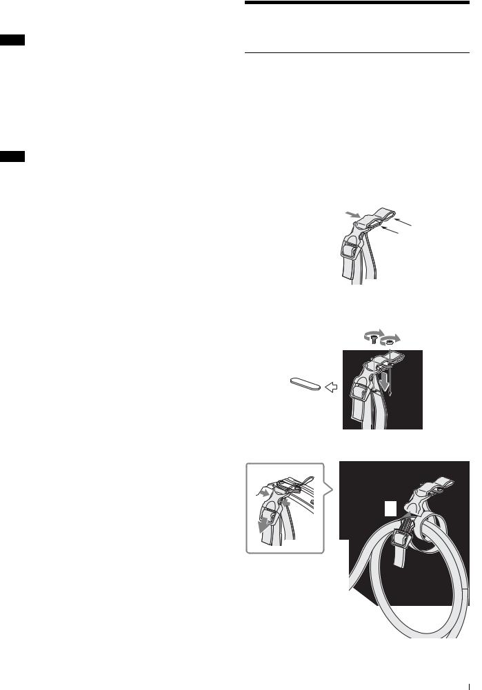
Adjusting the Shoulder Pad Position
You can shift the shoulder pad in the range of 28 mm (1 1/8 inches). This adjustment helps you get the best balance for shooting with the camera on your shoulder.
To adjust
1 Raise the lever in the center of the shoulder pad to unlock the shoulder pad, 2 slide the shoulder pad backward or forward until it is in the most convenient position, and 3 move the lever down to lock the shoulder pad in the selected position.
Shoulder pad lock lever
1
3
Bottom of the camera
Shoulder pad
2
Preparatory Settings
Adjusting the Black Balance and White
Balance
In order to maintain high picture quality when using the camera, it is necessary to set the black balance and white balance appropriately for the conditions.
Note
When a CCU or an external control device, such as an RCP/ RM, is connected, the black balance and white balance are controlled from the external device or the HKCU-FP1 attached to the CCU, and adjustment on the camera is disabled.
Black balance adjustment
The black balance needs adjustment in situations like the following:
•The first time the camera is used
•When the camera is used after a long period of disuse
•When the surrounding temperature changes greatly
•When the gain value is changed using the setup menus Normally, there is no need to adjust the black balance every time the camera is turned on.
White balance adjustment
Always adjust the white balance when lighting conditions change.
To adjust the black balance
Push the AUTO W/B BAL switch to BLK.
AUTO W/B BAL switch
Automatic black balance adjustment begins.
In automatic adjustment of black balance, both the black set and black balance are adjusted.
During adjustment, the message “ABB: EXECUTING” will be displayed on the viewfinder screen.
When the adjustment process is completed, the message “ABB: OK” will be displayed.
The adjusted value is automatically stored in memory.
The black balance values stored in memory will be preserved even when the camera power is turned off.
Notes
•During black balance adjustment, the iris will be automatically closed.
•During black balance adjustment, the gain switching circuit will work automatically, and the viewfinder screen will flicker several times. This is not a malfunction.
Preparatory Settings |
13 |
|
|
 Loading...