


HVR-M15
Table of contents
 Loading...
3-878-917-11 (1)
Digital HD
Videocassette
Recorder
Operating Instructions
Before operating the unit, please read this manual thoroughly,
and retain it for future reference.
HVR-M15AU/M15AN/M15AE/
M15AP
© 2008 Sony Corporation

2 Table of Contents
Chapter 1 Overview
Features...................................................................................................... 4
Location and Function of Parts................................................................ 6
Front Panel ....................................................................................................... 6
Rear Panel ...................................................................................................... 12
Supplied Remote Commander ....................................................................... 16
Displaying Various Data..........................................................................18
Chapter 2 Playback and Recording
Notes on Power Supply and Video Cassettes ......................................20
Preparing the Power Supply........................................................................... 21
Inserting/Ejecting Cassettes ........................................................................... 21
Notes on Playback/Recording........................................................................ 22
Installing the Unit Vertically.......................................................................... 23
Recording Format and Input/Output Signals........................................24
Major Differences among HDV1080i, DVCAM, and DV Formats.............. 24
Input/Output Signals in EE Mode.................................................................. 25
Recording Input Signals and Recording Formats .......................................... 26
Playback Tape Format and Output Signals.................................................... 26
Settings for Output Signals from Each Jack .................................................. 27
Playback ...................................................................................................29
Connections for Playback .............................................................................. 29
Settings for Playback ..................................................................................... 31
Playback Procedures ...................................................................................... 31
Playback Functions ........................................................................................ 32
Auto Repeat.................................................................................................... 35
Using the Unit as a Videocassette Recorder ........................................36
Connections for Recording ............................................................................ 36
Settings for Recording ................................................................................... 38
Recording Procedures .................................................................................... 40
Recording Functions ...................................................................................... 40
Chapter 3 Dubbing/Editing
Dubbing to Other Equipment..................................................................41
Connections for Dubbing ............................................................................... 41
Dubbing Procedures....................................................................................... 44
Editing (Connecting a Computer) .......................................................... 45
Connecting the Unit to a Computer ............................................................... 45
Preparations.................................................................................................... 46
Table of Contents

Table of Contents 3
Chapter 4 Adjusting and Setting Through Menus
Operating Menus .....................................................................................48
Menu Structure............................................................................................... 49
Menu Contents ............................................................................................... 50
Chapter 5 Maintenance
Troubleshooting ......................................................................................59
Warning Indicators and Messages.........................................................65
Notes on Use............................................................................................ 67
Notes on the Videocassette Recorder............................................................. 67
Cleaning of the Video Heads ......................................................................... 67
Notes on the Video Cassettes......................................................................... 68
About Moisture Condensation ....................................................................... 69
Digital Hours Meter ....................................................................................... 70
About the Built-in Rechargeable Battery....................................................... 70
Using your Videocassette Recorder abroad ................................................... 70
Notes on the License...................................................................................... 70
Appendix
Notes on Dubbing.................................................................................... 71
About i.LINK............................................................................................. 74
Specifications ..........................................................................................75
Index .........................................................................................................78
Submenu Index........................................................................................ 80

4 Chapter 1 Overview
Chapter
1
Overview
Features
The HVR-M15AU/M15AN/M15AE/M15AP is a
digital HD videocassette recorder supporting the HDV
and DVCAM/DV formats. The unit produces stable,
superior picture quality using digital processing and by
separating image signals into color difference signals
and a luminance signal (component video).
The main features of the unit are described below.
HDV/DVCAM/DV format
The unit can perform HDV/DVCAM/DV recording and
playback on a DVCAM format or DV format video
cassette.
• HDV format: The unit can perform HDV (High-
Definition Digital Video) recording and playback. The
compression system of the HDV format is the MPEG2
system adopted in high-definition broadcasting and the
Blu-ray Disc System. The unit adopts the 1080
scanning lines (interlaced 1080/60i, 1080/50i,
progressive 1080/24p, 1080/30p and 1080/25p) format
of the HDV specifications. The recording bit rate is
approximately 25 Mbps. The unit is equipped with
i.LINK digital interfaces, and can be digitally
connected with televisions or computers which are
compatible with the interfaces.
• DVCAM/DV format: DVCAM is based on the
consumer DV format, which uses the 4:1:1 component
digital format (60i) or the 4:2:0 format (50i), and
provides a 1/4-inch digital recording format for
professional use. The unit provides both DVCAM
format recording/playback and DV format in SP mode
recording/playback.
For details, see “Major Differences among HDV1080i,
DVCAM, and DV Formats” on page 24.
Compatible with both interlaced and
progressive HDV recording/playback
The unit can record or play back HDV 1080/60i, 1080/
24p, 1080/30p, 1080/50i and 1080/25p videos.
Also, the unit can play back HDV 720/30p, 720/24p and
720/25p videos.
(For recording, signals can be input only via an i.LINK
digital interface.)
Here for the unit, 60i indicates field frequency 59.94 Hz.
24p and 30p indicate frame frequency 23.98 Hz and 29.97 Hz,
respectively.
High definition down convert function
When you want to play back a tape recorded in HDV
format, you can down convert images to output them.
This function allows you to preview recorded-images
on a monitor which is not compatible with the High-
Definition (HD) format. Also, you can select an aspect
ratio from SQUEEZE, LETTER BOX (except HDV/
DV jack output), or EDGE CROP.

Chapter 1 Overview 5
Chapter 1 Overview
Multiple input/output interfaces
The following jacks are provided with the unit and
enable connection with various devices:
• Input jacks: S VIDEO IN jack, VIDEO IN jack and
AUDIO IN jacks
• Output jacks: COMPONENT OUT jacks, S VIDEO
OUT jack, VIDEO OUT jack and AUDIO OUT jacks
• Input-output jack: HDV/DV jack
JOG AUDIO function
If you use the optional DSRM-10 remote control unit
(not supplied), audio can be monitored at various
playback speeds in jog/shuttle mode. (Jog audio cannot
be output when the tape is recorded in HDV format.)
Screen Language Setting
You can select the language to be used for screen
displays.
The default language setting is English.
See “LANGUAGE” in the “OTHERS” menu on page 57 for
details on how to change the screen language.
Compact size allowing vertical installation
The compact size of the unit allows installation in a
vertical position and saves space. During non-linear
editing, you can install the unit in a vertical position next
to the computer and save working space.
Easy maintenance functions
• Self-diagnostics/alarm functions:
The system automatically detects an invalid operation,
bad connection, or a malfunction, and outputs a
description, a cause, and a recovery method to the
COMPONENT OUT jacks, S VIDEO OUT jack and
VIDEO OUT jack.
• Digital hours meter:
A digital hours meter counts four types of time data—
operating time, drum rotation time, tape running time,
and tape threading/unthreading. The digital hours data
is indicated on the menu.
........................................................................................
, , and are trademarks of Sony
Corporation.
is a trademark of Sony Corporation and
Victor Company of Japan, Ltd.
All other product names mentioned here may be the
trademarks or registered trademarks of their respective
companies. “™” and “®” are not mentioned in every
case in this manual.
6 Chapter 1 Overview
Chapter 1 Overview
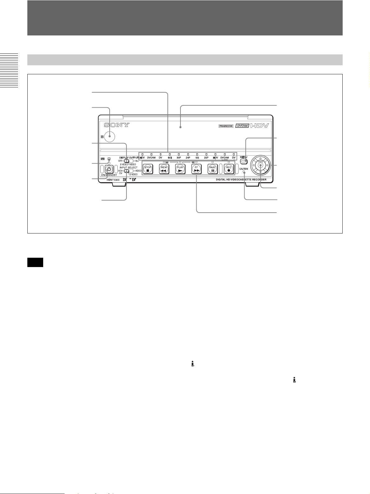
Location and Function of Parts
a Remote sensor
In addition to the Remote Commander supplied with the
unit, the unit accepts signals from any Sony Remote
Commander whose command mode is set to VTR4.
To disable control from a Remote Commander, set
[COMMANDER] in the [OTHERS] menu to
[CONTROL S].
b DISPLAY OUTPUT switch
Selects the destination for the text data to be
superimposed via output jacks.
OFF: Does not output text data to superimpose.
S VIDEO/VIDEO:
Superimposes text data to S VIDEO OUT jack and
VIDEO OUT jack.
ALL: Superimposes text data to COMPONENT OUT
jacks, S VIDEO OUT jack and VIDEO OUT jack.
For details on text data, see “Displaying Various Data” on
page 18.
c q (cassette) indicator
Lights when a digital video cassette is loaded.
Does not light up when there is no cassette loaded in the
unit.
This indicator blinks while a cassette is being ejected.
For details, see “Inserting/Ejecting Cassettes” on page 21.
d ON/STANDBY switch and lamp
Press this switch to turn the unit on, and the ON/
STANDBY lamp lights up in green. When you press
this switch again, the unit goes into the standby mode
and the lamp lights up in red.
e INPUT SELECT switch
Use this button to select the signal input jack from the
HDV/DV jack, S VIDEO IN jack, and VIDEO IN
jack.
HDV/DV: Inputs a signal from the HDV/DV jack.
SVIDEO:Inputs a signal from the S VIDEO IN jack.
VIDEO: Inputs a signal from the VIDEO IN jack.
Front Panel
1 Remote sensor
3 q (cassette)
indicator
1 Tape transport control
section (see page 8)
2 DISPLAY OUTPUT
switch
5 INPUT SELECT switch
6 Cassette Lid
2 Indicator section
(see page 10)
4 ON/STANDBY
switch and lamp
8 J/j/K/k buttons
9 EXEC button
0 CAUTION indicator
7 MENU button
Note

Chapter 1 Overview 7
Chapter 1 Overview
• Do not change the setting of this switch while
recording is in progress, or it will cause noise to be
added to images and sounds. Also, the part of the tape
where the change of setting is applied will not be
recorded properly. Also, the time code may be
recorded discontinuously.
• If you change the setting of this switch while recording
is in progress, the output signal via the HDV/DV jack
may be interrupted. Also, the unit may detect signals,
such as a copyright information signal, incorrectly.
• When a signal is input via the HDV/DV jack, the
settings of the menus listed below are unavailable.
– 60i/50i SEL
– AUDIO MODE
–AUDIO LOCK
– AUDIO AGC
– AUDIO REC LV
f Cassette Lid
Open this lid to insert or eject a cassette.
For details on cassettes that can be used, see “Notes on
Power Supply and Video Cassettes” on page 20.
For details of inserting or ejecting a cassette, see “Inserting/
Ejecting Cassettes” on page 21.
g MENU button
Press this button to display the menu list on screen.
For details on the menus, see “Operating Menus” on page
48.
h J/j/K/k buttons
Use these buttons in making menu settings and other
settings.
i EXEC (execute) button
Use this button in menu settings.
j CAUTION indicator
Blinks when an error occurs.
For details on cautions, see “Self-diagnosis display/Warning
Indicators” on page 65.
Notes

8 Chapter 1 Overview
Chapter 1 Overview
Location and Function of Parts
1 Tape transport control section
a Tape transport indicator
b REC (record) button
When you press and hold this button, then press the
PLAY button, each indicator lights and recording starts.
If you press this button while the tape is stopped, you
can check EE picture and audio signals for a short time.
When the HDV/DV jack is selected, if [HDV/DV IN
TC] in the [TC/UB SET] menu is set to [EXTERNAL],
you can also check the EE time code signals. Press the
STOP button to end the check.
For details, see “EE/PB SEL” in the “IN/OUT REC” menu
on page 52.
For details on time codes, see “TC/UB SET” on page 56.
• The unit does not have an LP recording mode for the
consumer DV format. Only SP recording mode is
available.
• To set the unit to recording pause mode with the
DSRM-10 remote control unit (not supplied), press the
PAUSE button while holding down the PLAY button
to set the unit to the playback pause mode, then press
the REC button on the DSRM-10.
• When the recording mode is set to HDV format, it may
take a few seconds to start recording. During this time,
the REC indicator blinks.
c PAUSE button
Press this button to set the unit to pause mode. The
indicator lights during recording or playing. Press this
button again to resume the operation.
d FF (fast forward) button
When you press this button, the indicator lights and the
tape is fast forwarded. During fast forward, the picture
does not appear on the monitor. (You can see the picture
as it is seen in EE mode
1)
during fast forward.) To locate
a scene while monitoring the picture, press and hold this
button during fast forward, playback or in the playback
pause mode (picture search).
• If you set [EE/PB SEL] in the [IN/OUT REC] menu to
[PB], EE picture and EE audio signals are not output
(page 52).
2 REC (record) button
4 FF (fast forward) button
7 STOP button
5 PLAY button
3 PAUSE button
6 REW (rewind) button
1 Tape transport indicator
Notes
Notes
........................................................................................................................................................................................
1) “EE” stands for “Electric to Electric.” In EE mode, the video and audio signals input to the VCR’s recording circuitry do not
pass through any magnetic conversion circuits but are output via electric circuits only. This mode is used to check the input
signals and adjust input levels. The pictures output in EE mode are referred to as EE pictures.

Chapter 1 Overview 9
Chapter 1 Overview
• If you set [FF/REW SPEED] in the [VTR SET] menu
to [SHUTTLEMAX], the picture is played back during
fast forward.
For details on running speed with [SHUTTLEMAX], see
“FF/REW SPEED” in “VTR SET menu” on page 55.
e PLAY button
When you press this button, the indicator lights and
playback begins.
If you press this button while holding down the REW
button during stop, the tape is rewound to its beginning
and starts playing automatically (during rewind, the
REW indicator lights and the PLAY indicator blinks).
• When the unit is playing back a part of the tape where
the recording format has been changed to HDV format,
DVCAM format, or DV format, or between 60i system
(including 24p and 30p) and 50i system (including
25p), the picture and sound may be distorted.
• The unit cannot play back a tape recorded in the LP
recording mode of the consumer DV format.
f REW (rewind) button
When you press this button, the indicator lights and the
tape starts rewinding. During rewind, the picture does
not appear on the monitor. (You can see the picture as it
is seen in EE mode during rewind.) To locate a scene
while monitoring the picture, hold this button down
during rewind, playback or in the playback pause mode.
If you press the PLAY button while holding down this
button during stop, the tape is rewound to its beginning
and starts playing automatically. (During rewind, the
REW indicator lights and the PLAY indicator blinks.)
• If you set [EE/PB SEL] in the [IN/OUT REC] menu to
[PB], EE picture and EE audio signals are not output
(page 52).
• If you set [FF/REW SPEED] in the [VTR SET] menu
to [SHUTTLEMAX], the picture is played back during
rewind.
For details on running speed with [SHUTTLEMAX], see
“FF/REW SPEED” in “VTR SET menu” on page 55.
g STOP button
Press this button to stop the tape transport operation
completely
.
If you set [EE/PB SEL] in the [IN/OUT REC] menu to
[PB], EE picture and EE audio signals are not output
during stop (page 52).
Notes
Notes
Note
10 Chapter 1 Overview
Chapter 1 Overview
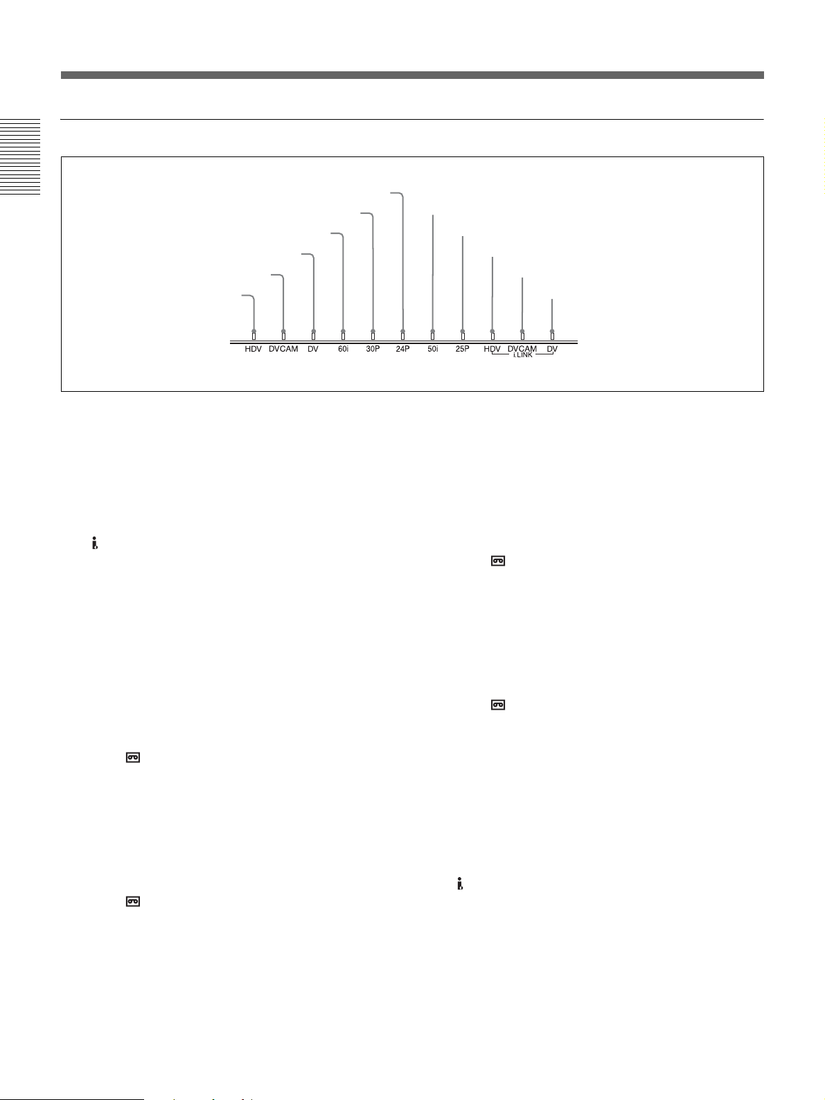
Location and Function of Parts
2 Indicator section
a HDV indicator
Lights when the unit is in either of the following
operating states.
• When a tape recorded in HDV format is being played
back.
• When [HDV/DV SEL] in the [IN/OUT REC] menu is
set to [AUTO] and HDV signals are being input from
the HDV/DV jack.
• When [HDV/DV SEL] in the [IN/OUT REC] menu is
set to [HDV].
b DVCAM indicator
Lights when the unit is in either of the following
operating states.
• When a tape recorded in DVCAM format is being
played back.
• When the following four conditions are met:
– When [HDV/DV SEL] in the [IN/OUT REC] menu
is set to [AUTO].
– When [ REC MODE] in the [IN/OUT REC] menu
is set to [DVCAM].
– When DV or DVCAM signals are being input from
any of the input jacks.
– During recording or in EE mode.
• When the following three conditions are met:
– When [HDV/DV SEL] in the [IN/OUT REC] menu
is set to [DV].
– When [ REC MODE] in the [IN/OUT REC] menu
is set to [DVCAM].
– During recording or in EE mode.
c DV indicator
Lights when the unit is in either of the following
operating states.
• When a tape recorded in DV format (SP mode only) is
being played back.
• When the following four conditions are met:
– When [HDV/DV SEL] in the [IN/OUT REC] menu
is set to [AUTO].
– When [ REC MODE] in the [IN/OUT REC] menu
is set to [DV].
– When DV or DVCAM signals are being input from
any of the input jacks.
– During recording or in EE mode.
• When the following three conditions are met:
– When [HDV/DV SEL] in the [IN/OUT REC] menu
is set to [DV].
– When [ REC MODE] in the [IN/OUT REC] menu
is set to [DV].
– During recording or in EE mode.
d 60i indicator
Lights when the unit is in one of the following operating
states.
• During recording or in EE mode when [60i/50i SEL] in
the [OTHERS] menu is set to [60i].
• When1080/60i signals or NTSC signals are input from
the HDV/DV jack.
• When a tape that has 1080/60i signals or NTSC signals
is being played back.
4 60i indicator
1 HDV indicator
7 50i indicator
2 DVCAM indicator
qa DV-i.LINK indicator
9 HDV-i.LINK indicator
0 DVCAM-i.LINK indicator
3 DV indicator
5 30p indicator
6 24p indicator
8 25p indicator

Chapter 1 Overview 11
Chapter 1 Overview
e 30p indicator
Lights when the unit is in either of the following
operating states.
• When a tape recorded in 1080/30p format or 720/30p
format is being played back.
• When 1080/30p signals are input from the HDV/DV
jack.
f 24p indicator
Lights when the unit is in either of the following
operating states.
• When a tape recorded in 1080/24p format or 720/24p
format is being played back.
• When 1080/24p signals are input from the HDV/DV
jack.
g 50i indicator
Lights when the unit is in one of the following operating
states.
• During recording or in EE mode when [60i/50i SEL] in
the [OTHERS] menu is set to [50i].
• When 1080/50i signals, or PAL signals are input from
the HDV/DV jack.
• When a tape that has 1080/50i signals or PAL signals
is being played back.
h 25p indicator
Lights when the unit is in either of the following
operating states.
• When a tape recorded in 1080/25p format or 720/25p
format is being played back.
• When 1080/25p signals are input from the HDV/DV
jack.
i HDV-i.LINK indicator
Lights when HDV signals are input/output through the
i.LINK interface.
j DVCAM-i.LINK indicator
Lights when DVCAM signals are input/output through
the i.LINK interface.
k DV-i.LINK indicator
Lights when DV signals are input/output through the
i.LINK interface.

12 Chapter 1 Overview
Chapter 1 Overview
Location and Function of Parts
a S VIDEO jacks
To connect a device equipped with S video jacks, use
the S VIDEO jacks on the unit.
If you use the S VIDEO jacks, you can input/output
high-quality video with less signal quality deterioration
than if connected to the standard VIDEO jack.
When the DISPLAY OUTPUT switch on the front
panel is set to S VIDEO/VIDEO or ALL, text data such
as the time code, menus, and alarm messages are
superimposed on an external monitor connected to the
S VIDEO OUT jack (page 18).
For details on the output of the S VIDEO jacks, see “Notes on
all video output jacks” on page 14.
b VIDEO jacks
Use these jacks to input and output analog video signals.
Text data is superimposed on a monitor in the same
way as with an S VIDEO jack connection (page 18).
For details on the output of the VIDEO jacks, see “Notes on
all video output jacks” on page 14.
c AUDIO jacks
Use these jacks to input and output analog audio signals.
When [AUDIO MODE] in the [AUDIO SET] menu is
set to [FS32K], sounds will be recorded on channels 1
and 2.
• When the audio mode is 32 kHz (4-channel), you can
set [AUDIO MIX] in the [AUDIO SET] menu to select
the audio signals to be output (page 54). When you
select [MIX], the audio output level becomes 50%
(–6 dB) of the original audio levels on each channel.
• If you input a sound at a level that exceeds the
acceptable range, the recorded sound is distorted.
For details on the available volume levels, see
“Specifications” on page 75.
d LANC jack
Use this jack when controlling the tape transport
operation of the unit using a device that has a LANC
1)
jack.
• The LANC jack on the unit has only LANC-S
functions. The unit has no LANC-M functions. A
device that is set to LANC-S mode cannot be
connected to the unit. Either the unit or the other
device may not operate properly.
• When using the unit as a player, set LANC mode on
the recorder to M. A VCR that does not have an M/S
switching function cannot be used to operate the unit.
Rear Panel
1 S VIDEO jacks
3 AUDIO jacks
5 RESET button
9 CONTROL S jack
8 HDV/DV jack
4 LANC jack
6 COMPONENT OUT jacks
2 VIDEO jacks
7 DC IN jack
Notes
Notes
.......................................................................................................................................................................................
1) LANC (Local Application Control bus system): Bidirectional interface used to control a consumer VCR

Chapter 1 Overview 13
Chapter 1 Overview
• When the device to be connected to the unit has a
LANC-M function to switch between SHUTTLE A/B,
select SHUTTLE A for an HDV-formatted tape, and
SHUTTLE B for a DVCAM/DV (SP)-formatted tape.
• A LANC connection transmits command signals for
playback, stop, pause playback, as well as the time
code, tape counter, and data status of the unit.
• Jacks labeled CONTROL L have the same function as
LANC jacks.
• There are some limitations when you edit an HDV-
formatted tape.
Refer to the “Notes” in “Editing (Connecting a Computer)”
on page 45.
e RESET button
If you press this button with the tip of a ballpoint pen or
similar tool, the following settings are initialized.
– [CLOCK SET] (page 58) and [60i/50i SEL] (page 58)
in the [OTHERS] menu.
– The settings on the unit other than the menu settings.
f COMPONENT OUT jacks
Use these jacks to output component signals.
To connect a device equipped component video input
connectors, use the COMPONENT OUT jacks on the
unit. If you use the COMPONENT OUT jacks, you can
output high-quality video with less signal quality
deterioration than if you use the S VIDEO jacks.
You can set the output video format by using
[COMPONENT] of [VIDEO OUT] in the [IN/OUT
REC] menu.
When the DISPLAY OUTPUT switch is set to ALL,
text data such as time code, menu, and alarm messages
are superimposed on a monitor connected using the
COMPONENT OUT jacks (page 18).
• When you change the video format setting of
[COMPONENT] of [VIDEO OUT] in the [IN/OUT
REC] menu, the video signal output from the
S VIDEO OUT jack, VIDEO OUT jack, or HDV/
DV jack may be distorted for a moment.
• When you play back a tape in DVCAM/DV format and
while an EE picture in NTSC/PAL is displayed, either
the 480i resolution or the 576i resolution is output,
regardless of the setting of [COMPONENT] of
[VIDEO OUT] in the [IN/OUT REC] menu.
• When [COMPONENT] of [VIDEO OUT] in the [IN/
OUT REC] menu is set to either [1080i/480i] or
[1080i/576i], 1080/24p and 1080/30p video signals are
converted to 1080/60i and 1080/25p video signals are
to 1080/50i, and output.
• When you play back an HDV-formatted tape with
copyright protected signals or input HDV signals with
copyright protection to the HDV/DV jack, pictures
may be output in either 480i (NTSC) or 576i (PAL)
format, regardless of the setting of [COMPONENT] of
[VIDEO OUT] in the [IN/OUT REC] menu.
• The output level of the COMPONENT OUT jacks is as
follows:
Output at 480i (NTSC)
With [BETACAM] selected in [480i LEVEL] of the
[IN/OUT REC] menu
Y: 1.0 Vp-p
(with 0.286 Vp-p sync negative,
output impedance 75 Ω (ohms), unbalanced)
Pb/Cb/B-Y, Pr/Cr/R-Y: 0.7 Vp-p
(output impedance 75 Ω (ohms), unbalanced)
(75% color bars with 7.5 IRE setup)
With [SMPTE] selected in [480i LEVEL] of the [IN/
OUT REC] menu
Y: 1.0 Vp-p
(with 0.3 Vp-p sync negative,
output impedance 75 Ω (ohms), unbalanced)
Pb/Cb/B-Y, Pr/Cr/R-Y: 0.7 Vp-p
(output impedance 75 Ω (ohms), unbalanced)
(100% color bars with no setup)
Output with other settings
Y: 1.0 Vp-p
(output impedance 75 Ω (ohms), unbalanced)
Pb/Cb/B-Y, Pr/Cr/R-Y: 0.7 Vp-p
(output impedance 75 Ω (ohms), unbalanced)
(100% color bars with no setup)
480i/480p:
Y: with 0.3 Vp-p sync negative
1080i/720p:
Y/Pb/Pr: with 0.6 Vp-p 3-level sync
g DC IN jack
Connect to the AC outlet using the supplied AC
Adaptor.
Notes
(Continued)

14 Chapter 1 Overview
Chapter 1 Overview
Location and Function of Parts
h HDV/DV jack (6-pin)
Use this jack to input/output digital signals that comply
with the i.LINK standard. Use this jack when a device
connected to the unit has an i.LINK jack. If you connect
the unit and another device using the HDV/DV jack,
you can minimize deterioration of picture quality during
recording, dubbing, or capturing still pictures, all by
means of digital signals processing.
For details, refer to the instruction manual of the external
device.
• When you connect a computer and the unit with an
i.LINK cable, check the direction of the jack. If you
forcibly insert the jack, the terminal may be damaged
or cause the unit to malfunction.
• This jack is only compatible with HDV (1080i)/
DVCAM/DV signals.
For details, see “About i.LINK” on page 74.
• If the unit is connected to a device equipped with an
i.LINK jack, when you intend to disconnect or
reconnect the i.LINK cable, turn off the device and
pull out the plug of its power cord from the AC outlet
beforehand. If you connect or disconnect the i.LINK
cable while the device is connected to the AC outlet,
high-voltage current (8 to 40 V) is output from the
i.LINK jack of the device to the unit. This may cause a
malfunction.
• Even though the HDV/DV jack of the unit is a 6-pin
type, no power is supplied.
For details on each setting when HDV/DV signals are input,
see “HDV/DV SEL” (page 50).
• When you change the video format setting of
[COMPONENT] in [VIDEO OUT] of the [IN/OUT
REC] menu, the video signal output from the
S VIDEO OUT jack, the VIDEO OUT jack, or the
HDV/DV jack may be distorted.
For details on the output of the HDV/DV jack, see “Notes
on all video output jacks” (page 14).
i CONTROL S jack
Connect this jack to a DSRM-10 remote control unit
(not supplied) to operate the unit.
You can also use a DSRM-20 (no longer manufactured:
not supplied).
When you use a CONTROL S device, set
[COMMANDER] in the [OTHERS] menu to
[CONTROL S].
• When you change the video format setting of
[COMPONENT] of [VIDEO OUT] in the [IN/OUT
REC] menu, the video signals output from S VIDEO
OUT jack, VIDEO OUT jack, or HDV/DV jack may
be distorted.
• The unit is only compatible with standard video
signals. If you input the types of video signals shown
below, recorded picture and sound may be distorted.
– Signals from some home game machines
– Blue background screen or gray background screen
images from a consumer VCR
– Pictures played at a speed other than normal by a
VCR that does not have TBC (Time Base Corrector)
– Video signals in which the sync signals are distorted
– Signals from a defective cassette (tape or recording
condition is bad) played by an analog VCR that does
not have TBC
• When DVCAM/DV signals which are input from the
HDV/DV jack, or video signals which are from the
VIDEO IN jacks or S VIDEO IN jacks, are output to
each analog output jack, the distortion of the video
signals occurs at the bottom of the TV monitor display
due to the jitter. Depending on the display area of the
TV monitor you have, the distortion of the picture may
appear at the bottom of the screen. This is not a
malfunction.
Pictures may be distorted or not be displayed
depending on the TV monitors. This will not appear
while recording with the unit.
Be aware of these phenomena when you connect other
recording device via the analog jacks of the unit.
• Depending on the TV monitor being connected, the
screen may blink or be distorted when DVCAM/DV
signals which are input from the HDV/DV jack, or
video signals which are from the VIDEO IN jacks or S
VIDEO IN jacks, are output to the VIDEO OUT jacks.
Be aware of these phenomena when you connect other
recording device to these jacks. This will not appear
while recording with the unit.
• During recording or in EE mode, the subcarrier of the
color signal to be output from the unit is not
synchronized with the horizontal sync signal. The
color of the picture or the horizontal position of the
picture may be distorted depending on the type of
monitor connected to the unit.
Notes
Note
Notes on all video output jacks

Chapter 1 Overview 15
Chapter 1 Overview
• To output video signals to the VIDEO, S VIDEO, or
COMPONENT OUT jacks without text data, set the
DISPLAY OUTPUT switch to OFF, or press the
DATA CODE or SEARCH SELECT button on the
remote commander.
16 Chapter 1 Overview
Chapter 1 Overview
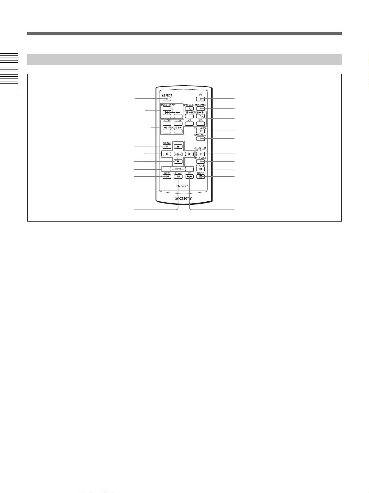
Location and Function of Parts
a Z EJECT button
b SEARCH SELECT buttons
Press these buttons to search for scenes using the search
function.
For details on the search function, see “Searching using the
search function” on page 34.
c Buttons for playing at various speeds
You can play back a tape at normal speed or at a speed
other than normal with these buttons.
For details, see “Playing at various speeds” on page 33.
d MENU button
Press this button to display the menu on the screen.
For details on the menu, see “Operating Menus” on page 48.
e J/j/K/k button
Press these buttons to operate the cursor on the menu
screen or to move the display position of the counter.
f EXEC (execute) button
Press this button to input the value set on various menu
setting screens.
g REC (record) buttons
When you press both these buttons at the same time, the
REC indicator and the PLAY indicator on the front
panel light and recording begins.
h REW (rewind) button
i PLAY button
j FF (fast forward) button
k STOP button
l PAUSE button
m DATA CODE button
Press this button to display the data codes (recording
date/time).
For details on data codes, see “Displaying information (data
codes) recorded on a tape” on page 32.
n COUNTER SELECT button
This button is not available for the unit.
o REW&PLAY (rewind and play) button
Press this button to rewind the tape to its beginning and
start playing automatically. (During rewind, the REW
indicator lights and the PLAY indicator blinks on the
unit.)
p SHUTTLE MAX button
During tape playback, press this button to play back the
video at the maximum speed.
Supplied Remote Commander
3 Buttons for playing at
various speeds
1 EJECT button
4 MENU button
2 SEARCH SELECT
buttons
7 REC button
5 J/j/K/k button
8 REW button
6 EXEC button
9 PLAY button
ql 1 button
q; FF button
qa STOP button
qs PAUSE button
qd DATA CODE button
qf COUNTER SELECT button
qg REW&PLAY button
qh SHUTTLE MAX button
qj INDEX MARK button
qk END SEARCH button

Chapter 1 Overview 17
Chapter 1 Overview
q INDEX MARK button
Press this button during recording to mark an index.
For details on indexes, see “Marking an index” on page 40.
r END SEARCH button
Press this button to play back the end of the last recorded
part for only 5 seconds and stop automatically. Once
you eject the video cassette, this function does not
operate.
s 1 (on/standby) button
• The command mode of the supplied Remote
Commander is set to VTR4. You cannot change the
command mode setting.
• Set [COMMANDER] in the [OTHERS] menu to
[WIRELESS] to enable the Remote Commander to
control the unit (page 57).
• In addition to the Remote Commander supplied with
the unit, the unit accepts signals from any Sony
Remote Commander with a command mode set to
VTR4.
To disable control from Remote Commander, set
[COMMANDER] in the [OTHERS] menu to
[CONTROL S].
Before using Remote Commander
Remove the insulation sheet before using the Remote
Commander.
To change the battery of the Remote
Commander
1
While pressing on the tab, inset your fingernail into
the slit to pull out the battery case.
2
Place a new battery with the + side facing up.
3
Insert the battery case back into the Remote
Commander until it clicks.
Note on batteries
When the lithium battery becomes weak, the operating
distance of the Remote Commander may shorten, or the
Remote Commander may not function properly. In this
case, replace the battery with a Sony CR2025 lithium
battery. Use of another battery may present a risk of fire
or explosion.
Notes
WARNING
Battery may explode or leak if mistreated. Do not
recharge, disassemble or dispose of in fire.
Caution
Replace the battery with the specified type only.
Otherwise, fire or injury may result.
Insulation sheet
Tab

18 Chapter 1 Overview
Chapter 1 Overview
Displaying Various Data
The unit can display various superimposed text data on
the built-in LCD monitor, and also on an external
monitor connected to the unit. When external monitors
are connected to the unit, you can select the destination
of the text data to be displayed using the DISPLAY
OUTPUT switch.
In this operation manual, the menu screen, etc., is
displayed in English. You can change the desired
language with the screen language setting.
For details, see “LANGUAGE” in the “OTHERS” menu on
page 57.
Menu screen
Press the MENU button to display the menu screen.
For details on the menus, see “Chapter 4 Adjusting and
Setting Through Menus” on page 48.
Data display screen
You can confirm important information for normal
recording or playback, such as time code or remaining
tape time, on the screen.
You cannot specify the items of information to be
displayed.
a Format indicator
[HDV1080i], [HDV720p], [DVCAM], or [DV SP] are
displayed.
b 60i/24p/30p/50i/25p indicator
c Repeat indicator
Displays the repeat indicator when [AUTO REPEAT]
in the [VTR SET] menu is set to [ON] (page 55).
d HVR-DR60/HVR-MRC1 connection indicator
[HDD] is displayed while an HVR-DR60 is connected
using the HDV/DV jack. When an HVR-MRC1 is
connected, [CF] is displayed.
e Alarm indicator
Displays an alarm indicator.
For details on alarm indicators, see “Warning Indicators and
Messages” on page 65.
f x.v.Color indicator
Displays an x.v.Color indicator while pictures recorded
in x.v.Color are played back.
For details on x.v.Color, see “Playback with x.v.Color
output” on page 23.
g Tape transport mode indicator
Displays the tape transport mode.
h Time code indicator
In the drop frame mode, a period is displayed between
the minutes and seconds (i.e., 00:12.58:00).
When you playback a tape without a time code or with
a time code recorded in different formats, the time code
cannot be displayed correctly.
i Remaining tape time indicator
Displays the remaining tape time.
For details, see “ REMAINING” in the “DISPLAY SET”
menu on page 53.
• The remaining tape time displayed is an estimated
time.
• When you insert a cassette of which the tape has been
rewound to the beginning, this indicator does not show
the remaining tape time. The remaining tape time is
displayed after the tape runs for a while.
j INPUT SELECT indicator
Changes according to the position of the INPUT
SELECT switch. ([HDV/DV IN], [S VIDEO IN] or
[VIDEO IN])
k (Index) indicator
Displays when an index has been marked.
s
1
8
9
0
qa,qs
qf
qg
3
5
4
6
7
2
qd
Note
Notes

Chapter 1 Overview 19
Chapter 1 Overview
l Search indicator
Displays the search mode when you search for scenes
using the Remote Commander.
For details on the search function, see “Searching using the
search function” on page 34.
m Audio mode indicator
In the recording mode, displays when you select
[FS32K] for [AUDIO MODE] in the [AUDIO SET]
menu.
When you select [FS48K], is displayed.
During playback, displays the audio mode recorded on
the tape. During i.LINK input, displays the audio mode
of the signal input to the HDV/DV jack.
• The audio mode will not be displayed when [HDV/DV
SEL] in the [IN/OUT REC] menu is set to [HDV].
• Signals other than HDV/DVCAM lock mode will
become non-standard audio and / is
displayed during playback or when the signal is input
from the HDV/DV jack.
n Audio level meters
For details of the audio level meter display, see [AUDIO
MIX] in the [AUDIO SET] menu (page 54).
If the audio level meter turns red in EE or recording
mode, the sound will be distorted because the input level
is too high. (However, when the audio mode is set to
32 kHz (4-channel, 12 bits) and [AUDIO MIX] (page
54) is set to [MIX], the audio level meter does not turn
red regardless of the input level.) During playback or
while HDV/DV signals are input, the level meter does
not turn red.
o Date/time indicator
When you press the DATA CODE button of the Remote
Commander or set [DATA CODE] in the [DISPLAY
SET] menu to [DATE], you can display the recording
date/time.
For details on the date/time indicator, see “Displaying
information (data codes) recorded on a tape” on page 32.
Notes
Note
20 Chapter 2 Playback and Recording
Chapter
2
Playback and
Recording
Notes on Power Supply and Video Cassettes
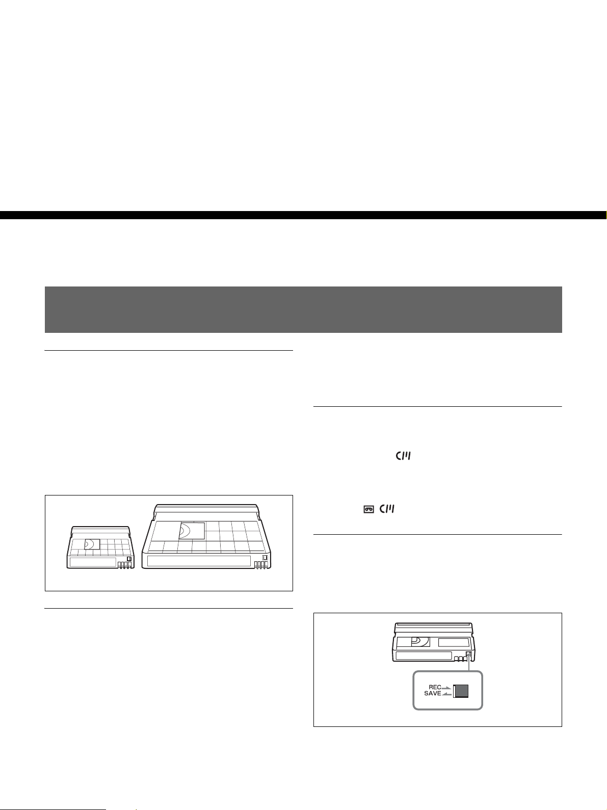
Usable cassettes
For recording in the HDV/DV format, we recommend
you use a DigitalMaster™ cassette such as standard
HDV/DVCAM/DV cassette (PHDV-276DM, etc.), or
mini HDV/DVCAM/DV cassette (PHDVM-63DM,
etc.).
For recording in the DVCAM format, we recommend
you use a standard DVCAM cassette, Mini-DVCAM
cassette, or DigitalMaster™ shown above.
Cassette compatibility
A DV format cassette tape can be used for HDV. The
recording bit rate and recording track pitch on a tape of
the HDV1080i system used for the HVR-M15AU/
M15AN/M15AE/M15AP are about 25 Mbps and
10 µm, respectively. The specifications are the same as
those of home use DV (SP) tapes. The recording time on
an HDV tape is also the same as that of a DV (SP) tape.
The track pitch of DVCAM is 15 µm, which is 1.5 times
that of HDV/DV (SP). Therefore, the recording time
using DVCAM recording on the same tape will be two-
thirds of the time available when HDV/DV (SP)
recording is used.
Cassette memory
Some mini cassettes and standard cassettes have the
cassette memory ( mark). The unit, however, does
not support the cassette memory function.
However, if you use the DSR-25/45/50 as a recorder, the
unit accesses cassette memory only if the recorder is set
to [AUTO ].
To save a recording
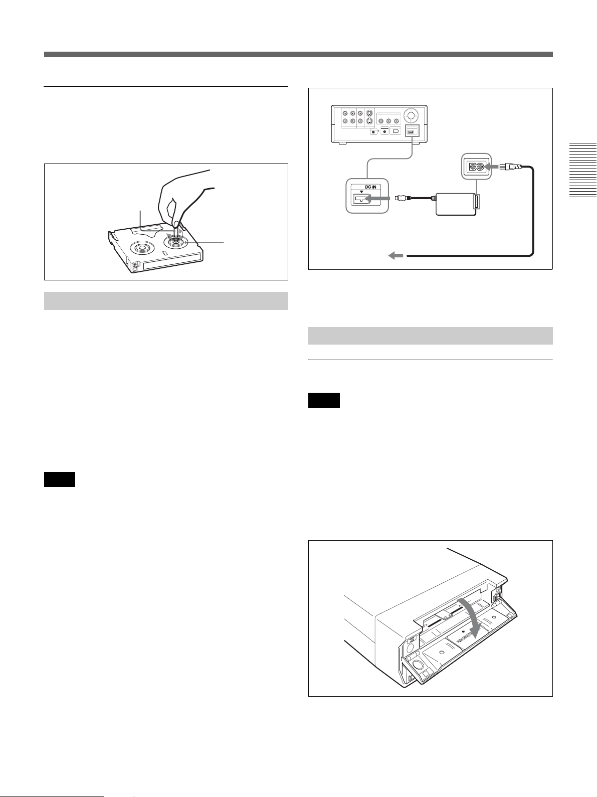
To prevent accidental erasure of a recording, set the
REC/ SAVE switch on the cassette to SAVE. To record
on a tape, set the switch to REC.
Mini cassette Standard cassette
REC/SAVE switch
Set to SAVE
Chapter 2 Playback and Recording 21
Chapter 2 Playback and Recording
Checking the tape for slack
Using a paper clip or a similar object, turn the reel
gently in the direction shown by the arrow. If the reel
does not move, there is no slack.
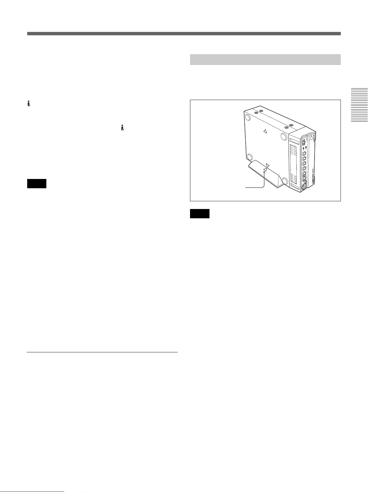
Connect the power cord (supplied) to the AC Adaptor
(supplied) and the DC plug of the AC Adaptor to DC IN
jack on the unit. Then, connect the power plug to the
wall outlet. When you disconnect the power code from
the wall outlet, be sure to unplug the power plug from
the wall outlet first.
PRECAUTION
Even if this unit is turned off, AC power (house current)
is still supplied to it while connected to the wall outlet
via the AC Adaptor.
• Never short-circuit the DC plug of the AC Adaptor
with a metal object. A short circuit can damage the
unit.
• Use a nearby wall outlet when using the AC Adaptor.
Disconnect the AC Adaptor from the wall outlet
immediately if any malfunction occurs.
• Do not use the AC Adaptor placed in a narrow space,
such as between a wall and furniture.
The [CLOCK SET] screen appears when you turn on the
unit for the first time.
For details on [CLOCK SET],see page 58.
To insert a cassette
• Do not insert the cassette forcibly. The unit may be
damaged.
• Do not eject/load the cassette in a place subject to light.
Close the cassette lid when the unit is in use. The
internal sensor of the unit may operate incorrectly if
too much light falls on the unit.
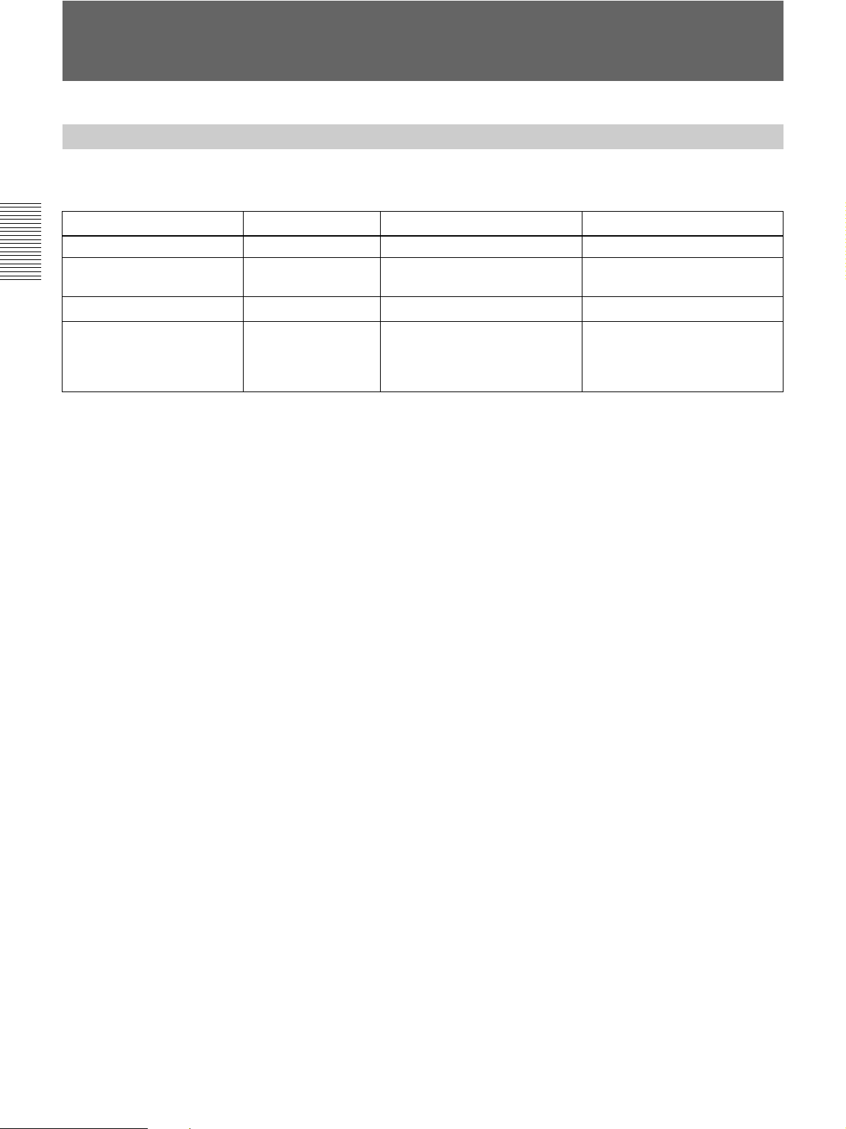
1
With the unit powered on, confirm that q indicator
is off, and then open the cassette lid.
Preparing the Power Supply
Notes
Paper clip, etc.
Reel
Inserting/Ejecting Cassettes
Notes
Power cord (supplied)
HVR-M15A (rear panel)
To DC IN
jack
AC Adaptor
(supplied)
To a wall outlet
(Continued)

22 Chapter 2 Playback and Recording
Chapter 2 Playback and Recording
Notes on Power Supply and Video Cassettes
2
After checking the tape for slack, hold the cassette
so that the tape window is facing upward, then insert
it into the unit.
The tape is inserted into the unit automatically.
• When inserting a cassette, hold the back edge of the
cassette in the center and push it until the cassette is
inserted deep into the unit. If you hold the ends, the
cassette may not be loaded properly.
• If the cassette does not load or is loaded only halfway,
eject it once, then insert it again. In such a case, if you
insert the cassette forcibly, the cassette may not be
loaded properly or malfunctions may occur.
• It takes a few seconds for the unit to recognize the
cassette and find the proper location on the tape being
loaded.
3
Close the cassette lid.
To eject the cassette
1
With the unit powered on, open the cassette lid.
Press the EJECT button located at the right side of
the cassette compartment.
The cassette is disengaged and ejected.
2
Remove the cassette from the unit and close the
cassette lid.
No compensation for contents of the recording
Contents of the recording cannot be compensated for if
recording or playback is not successful due to a
malfunction of the unit, video tape, etc.
Copyright precautions
Television programs, films, video tapes, and other
materials may be copyrighted. Unauthorized recording
of such materials may be contrary to the copyright laws.
Copyright signal
On playback
When the cassette you play back on the unit contains
copyright signals, you cannot copy it to a tape in another
device connected to your unit.
On recording
You cannot record software on the unit that contains
copyright control signals for copyright protection of
software.
[Cannot record due to copyright protection.] appears on
the screen of the external monitor if you try to record
such software. The unit does not record copyright
control signals on the tape when it records.
Notes
Tape window facing upward
Mini cassette
(Insert the mini cassette
into the center of the
cassette compartment.)
Standard
cassette
Notes on Playback/Recording
Chapter 2 Playback and Recording 23
Chapter 2 Playback and Recording
Limitations caused by differences in format
The unit can record and play back tapes recorded in
HDV format (1080/60i, 1080/24p, 1080/30p, 1080/50i
and 1080/25p), DVCAM format, or DV format (SP
mode).
The unit can input/output and record signals via the
HDV/DV jack.
The unit can play back pictures recorded in 720/24p,
720/25p or 720/30p of the HDV format, but you cannot
input/output these pictures via the HDV/DV jack.
The unit cannot input/output, record, or play back a tape
recorded in 720/60p or 720/50p of the HDV format, and
480p/576p of the SD format.
For details, see “Major Differences among HDV1080i,
DVCAM, and DV Formats” on page 24.
The unit can play back pictures recorded in 720/24p,
720/25p or 720/30p of the HDV format, but the formats
of the output pictures have limitations. For details, see
page 27.
If a tape contains portions recorded in two or more
different formats, the following limitations are applied
when you play back the tape with the unit:
• The image may be distorted and noise may occur at the
point where the recording format changes on the tape.
• The tape transport control buttons may be disabled
until the tape speed is stabilized.
Note on playback on other equipment
A tape recorded in HDV format with the unit cannot be
played back with devices not compatible with the same
format. We recommend confirming the contents of the
tape by playing back the tape with the unit before
playing it back on another video equipment.
Playback with x.v.Color output
The unit can play back pictures recorded in x.v.Color.
• x.v.Color is a brand name that Sony is proposing as a
easy-to-remember name for the xvYCC standard.
• The xvYCC standard is an international standard for
color space within moving images. The xvYCC
standard can reproduce a wider range of colors than the
standards used for current broadcasting.
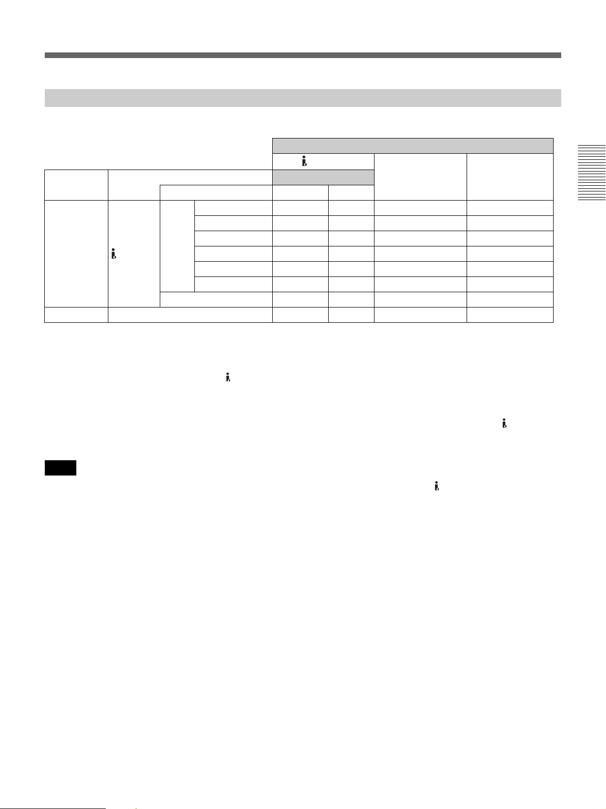
Put the unit into the supplied rack as illustrated below.
You can install it either standing on its left side or on its
right side.
• Be sure to use the supplied rack. Without the rack, the
unit may topple over and may be damaged or may
cause injury.
• Install the unit on a flat place.
• When inserting a cassette, hold the unit until it is
loaded into the unit. Otherwise the cassette may fall
out and the tape may be damaged.
For details on inserting a cassette, see “Inserting/Ejecting
Cassettes” on page 21.
• The name plate is located on the left side of the unit.
You may not see it when using the supplied rack.
Notes
Installing the Unit Vertically
Notes
Align the F on the unit
with the f on the rack.
24 Chapter 2 Playback and Recording
Chapter 2 Playback and Recording
Recording Format and Input/Output Signals
(This unit and other equipment for professional use may be functionally extended. For details, see the notes below
the table.)
1) The unit cannot record 4-channel sound in HDV format.
2) There are two modes for audio signal recording: Lock mode and Unlock mode. In Lock mode, the sampling frequencies of
audio and video are synchronized. In Unlock mode, adopted by the consumer DV format, the two sampling frequencies are
independent. Lock mode maintains high compatibility with higher formats and offers better digital processing and smoother
transition than Unlock mode when you edit audio.
3) The unit cannot record in DV format with 16 bit: 32 kHz or 44.1 kHz.
4) The unit has been functionally extended with a function for switching between Lock mode and Unlock mode.
5) The unit has been functionally extended with a function to enable selecting DF/NDF for 60i (including 24p and 30p) with
HDV or DV (SP) format.
6) The unit is not equipped with user bit setting function.
Major Differences among HDV1080i, DVCAM, and DV Formats
Specification HDV1080i
1)
DVCAM DV (SP)
Track pitch 10 µm 15 µm 10 µm
Audio sampling frequency 16 bit: 48 kHz 12 bit: 32 kHz
16 bit: 48 kHz
12 bit: 32 kHz
16 bit: 32 kHz, 44.1 kHz, 48 kHz
3)
Audio recording mode
2)
Lock mode Lock mode
Unlock mode
4)
Time code Drop frame mode
(60i/24p/30p only)
5)
No user bits
6)
NTSC: SMPTE time code
(DF/NDF, including user bits)
6)
PAL: EBU time code
(including user bits)
6)
Drop frame mode
(NTSC only)
5)
No user bits
6)
Chapter 2 Playback and Recording 25
Chapter 2 Playback and Recording
Select the signal input with the INPUT SELECT switch on the front panel (page 6).
1) The format of the picture output from the HDMI OUT jack and COMPONENT OUT jacks can be set in [COMPONENT] of [VIDEO OUT] in the [IN/OUT
REC] menu (page 51). For details, see the settings for down conversion (page 27).
2) The signals are down converted and output.
The format of the picture output from the VIDEO OUT jack and the S VIDEO OUT jack can be selected from [SQUEEZE], [LETTER BOX] and [EDGE
CROP] in [DOWN CONVERT] of [VIDEO OUT] in the [IN/OUT REC] menu (page 51).
3) When DVCAM/DV signals which are input from the HDV/DV jack, or video signals which are from the VIDEO IN jacks or S VIDEO IN jacks, are output
to each analog output jack, the distortion of the video signals occurs at the bottom of the TV monitor display due to the jitter. Depending on the display area
of the TV monitor you have, the distortion of the picture may appear at the bottom of the screen. This is not a malfunction.
Pictures may be distorted or not be displayed depending on the TV monitors. This will not appear while recording with the unit.
Be aware of these phenomena when you connect other recording device via the analog jacks of the unit.
4) Depending on the TV monitor being connected, the screen may blink or be distorted when DVCAM/DV signals which are input from the HDV/DV jack,
or video signals which are from the VIDEO IN jacks or S VIDEO IN jacks, are output to the VIDEO OUT jacks.
Be aware of these phenomena when you connect other recording device to these jacks. This will not appear while recording with the unit.
• HDV 720/30p/25p/24p signals can be played back, but cannot be input/output via the HDV/DV jack on the unit.
• HDV 720/60p, HDV720/50p and SD 480p/576p signals cannot be input/output, recorded, or played back on the
unit.
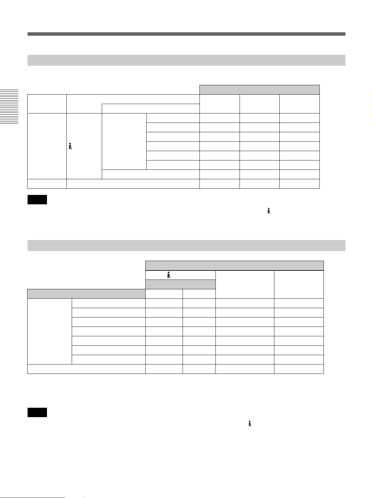
Input/Output Signals in EE Mode
a: Output, —: No output or N/A Output jack
HDV/DV
Input signal Input jack
Output signal format
COMPONENT OUT VIDEO/S VIDEO
Input format DVCAM/DV HDV
1080/60i — — a
1)
a (480i)
2)
1080/24p — — a
1)
a (480i)
2)
HDV 1080/30p — — a
1)
a (480i)
2)
Digital signal HDV/DV 1080/50i — — a
1)
a (576i)
2)
1080/25p — — a
1)
a (576i)
2)
720/30p/25p/24p — — — —
DVC A M/DV — — a
3)
a
3)
Analog signal VIDEO/S VIDEO a — a
3)
a
3) 4)
Notes
26 Chapter 2 Playback and Recording
Chapter 2 Playback and Recording
Recording Format and Input/Output Signals
Select the signal input with the INPUT SELECT switch on the front panel (page 6).
• HDV 720/30p/25p/24p signals can be played back, but cannot be input/output via the HDV/DV jack on the unit.
• HDV 720/60p, HDV720/50p and SD 480p/576p signals cannot be input/output, recorded, or played back on the
unit.
1) The format of the picture output from the COMPONENT OUT jacks can be set in [COMPONENT] of [VIDEO OUT] in the [IN/OUT REC] menu (page 51).
For details, see the settings for down conversion (page 27).
2) The signals are down converted and output.
For details of the format of signals output from each jack, see the settings for down conversion (page 27).
• HDV 720/30p/25p/24p signals can be played back but not input/output via the HDV/DV jack on the unit.
• HDV 720/60p, HDV720/50p and SD 480p/576p signals cannot be input/output, recorded, or played back on the
unit.
Recording Input Signals and Recording Formats
a: Recordable, —: Not recordable Recording format
Input signal Input jack
HDV DVCAM DV (SP)
Input format
1080/60i a ——
1080/24p a ——
HDV 1080/30p a ——
Digital signal HDV/DV 1080/50i a ——
1080/25p a ——
720/30p/25p/24p — — —
DVCAM /DV — aa
Analog signal VIDEO/S VIDEO — aa
Notes
Playback Tape Format and Output Signals
a: Output, —: No output or N/A Output jacks
HDV/DV
COMPONENT OUT VIDEO/S VIDEO
Output signal format
Format of the signals recorded on the tape DVCAM/DV HDV
1080/60i a a a
1)
a (480i)
2)
1080/24p a a a
1)
a (480i)
2)
HDV 1080/30p a a a
1)
a (480i)
2)
1080/50i a a a
1)
a (576i)
2)
1080/25p a a a
1)
a (576i)
2)
720/30p/24p — — a
1)
a (480i)
2)
720/25p — — a
1)
a (576i)
2)
DVCA M / DV ( SP) a — a a
Notes
Loading...