


 Loading...
4-582-207-12(1)
HD Multi Purpose
Camera
Operating Instructions
Before operating the unit, please read this manual thoroughly and retain it for future reference.
HXC-P70
© 2015 Sony Corporation

Table of Contents |
|
Overview ............................................................................. |
3 |
System Configuration ............................................................... |
3 |
Parts Identification .................................................................... |
7 |
Installation .......................................................................... |
9 |
Attaching a Lens ....................................................................... |
9 |
Adjusting the Flange Focal Length........................................... |
9 |
Mounting the Camera to a Tripod........................................... |
10 |
Setting the Area of Use ........................................................... |
11 |
Setting the Local Time............................................................ |
11 |
Preparatory Settings ........................................................ |
12 |
Configuring Control System Connection Settings.................. |
12 |
Setting the TLCS Function ..................................................... |
13 |
Setting the Focus Assist Function........................................... |
14 |
Menus ................................................................................ |
16 |
Operating the Menu ................................................................ |
16 |
Selecting the Page ................................................................... |
16 |
Setting the Menu Items ........................................................... |
17 |
Editing the USER Menu ......................................................... |
17 |
OPERATION Menu................................................................ |
20 |
PAINT Menu........................................................................... |
22 |
MAINTENANCE Menu ......................................................... |
25 |
FILE Menu.............................................................................. |
28 |
DIAGNOSIS Menu................................................................. |
30 |
Appendices ........................................................................ |
30 |
Precautions .............................................................................. |
30 |
Error Messages........................................................................ |
31 |
Specifications .......................................................................... |
31 |
Pin Assignment ....................................................................... |
32 |
Menu Tree ............................................................................... |
35 |
Open Software Licenses.......................................................... |
37 |
2
Overview
HD Multi Purpose Camera HXC-P70 is a high-definition video camera equipped with a 2/3-inch Exmor CMOS image sensor. A compact, box-shaped case enables the camera to be used for a variety of applications as it requires little space for installation.
In addition to use as a standalone camera using the SDI output, you can use this camera as a studio camera by directly connecting to the Camera Control Unit (CCU) HXCU-FB70 using fiber cables.
This camera can be used for a wide range of applications such as video production and security monitoring, as it is equipped with an optical ND filter powered by a servo motor that can be operated from a CCU, RCP, or RM, an electrical CC filter, a slow shutter capable of storing up to 64 frames, a gain up to +48 dB, an x2 or x4 digital extender (that enlarges the image by digital processing), and Total Level Control System.
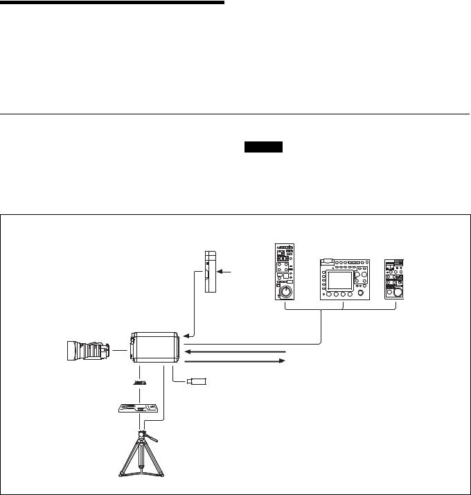
System Configuration
Peripherals and related devices for the camera are shown in figures.
Standalone operation example
Caution
Production of some of the peripherals and related devices shown in the figures has been discontinued. For advice on choosing devices, please contact your Sony dealer or a Sony sales representative.
|
Remote Control Panel |
AC Adapter |
RCP-1000 Series |
AC-DN10 |
Remote Control Unit |
|
RM-B750/B170 |
|
AC power |
Zoom Lens |
HXC-P70 |
(for ENG/EFP) |
|
V shoe 
Tripod adapter
VCT-14
Tripod for portable camera
CCA-5 cable/LAN cable b)
Sync signal input
Video output (2-system)
HD-SDI/SD-SDI a) (selectable)
TEST a)
USB flash drive
a) No subcarrier phase-lock function with respect to external reference is available for the TEST signal output from the camera.
b) A LAN cable can be used only to connect the RCP-1500/1501. To connect it, power needs to be supplied via a PoE hub or power needs to be supplied to the EXT DC IN connector of the RCP-1500/1501.
3

System operation example: When connected with an optoelectric composite cable
Picture monitor
|
Sync signal input |
Prompter video input |
Zoom Lens (for |
HXC-P70 |
|
ENG/EFP) |
Optoelectric composite |
|
|
cable a) |
|
|
|
HD-SDI/SD-SDI/VBS/HDMI video output |
|
Camera Control Unit |
|
|
HXCU-FB70 |
AC power |
V shoe |
USB flash |
CCA-5 cable / LAN |
|
||
|
drive |
cable b) |
Tripod adapter
VCT-14
|
Prompter video output |
Tripod for |
|
portable camera |
Remote Control Panel |
|
|
|
RCP-1000 Series |
a)The maximum transmission distance is approximately 500 m when using Sony CCFN-25/50/100/150/200/250 Hybrid Fiber Cable (when camera head + portable lens).
b)A LAN cable can be used only to connect the RCP-1500/1501. To connect it, power needs to be supplied via a PoE hub or power needs to be supplied to the EXT DC IN connector of the RCP-1500/1501.
4

System operation example: When connected with single-mode optical fiber cables
|
|
AC Adapter |
Picture monitor |
|
|
AC-DN10/DN2B |
|
|
|
|
|
|
|
AC power |
|
|
|
Sync signal input |
Prompter video input |
Zoom Lens (for |
HXC-P70 |
Single-mode |
|
ENG/EFP) |
|
optical fiber cables |
|
|
|
(pair) a) |
|
|
|
|
HD-SDI/SD-SDI/VBS/HDMI video output |
|
|
Camera Control Unit |
|
|
|
HXCU-FB70 |
AC power |
V shoe |
USB flash |
|
CCA-5 cable / LAN |
|
|
||
|
drive |
|
|
|
|
cable b) |
Tripod adapter
VCT-14
|
Prompter video output |
Tripod for |
|
portable camera |
Remote Control Panel |
|
|
|
RCP-1000 Series |
a)The maximum transmission distance is approximately 10 km when using general single-mode fiber cables with LC connectors.
b)A LAN cable can be used only to connect the RCP-1500/1501. To connect it, power needs to be supplied via a PoE hub or power needs to be supplied to the EXT DC IN connector of the RCP-1500/1501.
5

System operation example: When connected using Power Supply Unit HXCE-FB70
Picture monitor
|
|
|
|
Sync signal input |
Prompter video input |
Zoom Lens (for |
HXC-P70 |
Optoelectric |
Single-mode |
|
|
ENG/EFP) |
|
composite |
|
optical fiber |
|
|
|
cable a) |
|
cables b) |
|
|
|
|
|
|
HD-SDI/SD-SDI/VBS/ |
|
|
|
Power Supply |
Camera Control Unit |
HDMI video output |
|
|
|
Unit |
HXCU-FB70 |
AC power |
V shoe |
|
|
HXCE-FB70 |
|
|
|
USB flash |
|
|
CCA-5 cable / LAN |
|
|
|
|
|
||
|
|
drive |
AC power |
cable c) |
|
Tripod adapter 
VCT-14
|
Prompter video output |
Tripod for |
|
portable camera |
Remote Control Panel |
|
|
|
RCP-1000 Series |
a)The maximum transmission distance is approximately 500 m when using Sony CCFN-25/50/100/150/200/250 Hybrid Fiber Cable (when camera head + portable lens).
b)The maximum transmission distance is approximately 10 km when using general single-mode fiber cables with LC connectors.
c)A LAN cable can be used only to connect the RCP-1500/1501. To connect it, power needs to be supplied via a PoE hub or power needs to be supplied to the EXT DC IN connector of the RCP-1500/1501.
6

Parts Identification
Front |
a Front tally lamp |
The tally lamp lights when a tally signal is input to the EXT I/O connector of the HXCU-FB70 when the HXCU-FB70 is connected, and when a tally signal is input to the EXT I/O connector of the camera when it is used as a standalone camera.
The tally lamp does not light when a call signal is generated by pressing the CALL button.
You can attach the supplied number plate to display the camera number.
b LENS connector (12-pin)
Connect the cable of the lens (optional). The camera can control the lens functions through this cable.
Connect the lens cable so that v is at the top.
c Lens cable clamp
d Lens mount safety rubber e Lens mount cap
f Lens fixing lever
g ND filter select knob
To select the built-in ND filters (1: clear, 2: 1/4 ND, 3: 1/16 ND, 4: 1/64 ND).
Rear |
a Rear tally lamp |
The tally lamp lights when a tally signal is input and when a call signal is generated, for example, by pressing the CALL button. However, turning off the CALL setting on the M06 <TALLY> page disables the tally lamp when a call signal is generated by pressing the CALL button.
The rear tally lamp also serves as a battery alarm function.
If the voltage of the XLR input connected to the camera decreases, the rear tally lamp flashes, and if the limit becomes close to being reached, the rear tally lamp switches to high-speed flashing.
The alarm voltage for starting flashing can be set in the BEFORE END item of the <BATTERY ALARM> page on the MAINTENANCE menu, and the alarm voltage for switching to high-speed flashing can be set in the END item.
If a call signal is generated while the battery alarm function is operating, the rear tally lamp goes out.
If you want to operate the tally function and call function, set the BATTERY ALARM item of the <BATTERY ALARM> page on the MAINTENANCE menu to OFF.
For details, see “MAINTENANCE Menu” (page 25).
b DISPLAY/MENU switch
Select the display on the screen connected to the SDI connector (VF Setting) or GL/TEST connector.
DISPLAY: To display various textual information, such as messages showing the camera settings and operating status, in addition to camera images.
z (OFF): To not display textual information and markers. MENU: To display menus for camera settings, in addition to camera
images.
c Menu control knob (rotary encoder)
Used to select settings from menus (by rotating it) and to confirm settings (by pushing it).
d EXT I/O (external input/output) connector (D-sub, 9-pin)
Connect an external device.
7

e REMOTE connector (8-pin)
For connection to an RM-B170/B750 Remote Control Unit, RCP-1000 Series Remote Control Panel, or another external control device.
Note
When using the camera by connecting to a camera control unit, do not connect, for example, a remote control panel to this connector.
f  (USB) connector
Connect a USB flash drive to save or load a configuration data file.
g  (LAN) connector (RJ-45 type, 8-pin)
To connect to a LAN. Use a LAN cable (shielded, category 5 or above) to connect to the hub of the LAN (10BASE-T/100BASE- TX).
h CAMERA POWER switch and indicator
To turn the power ON/OFF.
ON: Set the switch to the ? side. The indicator lights green. OFF: Set the switch to the 1 side.
i CONDITION indicators
To indicate the communication status and power status of the camera and CCU based on the light reception level and the voltage reaching the camera.
Indication |
Meaning |
Both top and bottom lit green |
State is excellent. |
|
|
Only bottom lit green |
State is fairly good. |
|
|
Only top lit yellow |
State has deteriorated. |
|
|
Only bottom lit red |
State has become extremely poor (the |
|
connection between the camera and CCU |
|
needs to be checked). |
|
|
jCCU (Camera Control Unit) connector (optoelectric composite connector)
To connect to the HD Camera Control Unit HXCU-FB70. When connected with an optoelectric composite cable, all the
signals of the camera including the power supply, control signals, video signals, and audio signals can be transmitted/received with the one optoelectric composite cable.
When connected with a pair of single-mode fiber cables, all the signals except the power supply can be transmitted/received with the pair of single-mode fiber cables.
k DC IN (DC power supply input) connector (XLR 4-pin)
For connection to an AC-DN10 AC adapter, etc. to supply power to the camera.
l NETWORK indicator
To indicate the state when connected to a network system. Lit: Successfully connected to an external control device
(RCP-1000 Series remote control panel, etc.). Flashing: Unable to connect to an external control device
(RCP-1000 Series remote control panel, etc.) properly.
Off: A LAN cable is not connected or the connection settings of the network system are not configured.
For details on the adjustment, see “Configuring Control System Connection Settings” (page 12), “MAINTENANCE Menu” (page 25), “DIAGNOSIS Menu” (page 30).
m SDI 1 (serial digital interface) connector and SDI 2 connector (BNC type)
For HD-SDI or SD-SDI signal output.
HD-SDI signal and SD-SDI signal output can be selected on the menu.
Note
The functions that can be displayed differ depending on the output settings.
For details on the adjustment, see “Connector Output Settings and Display Functions” (page 8).
n GL/TEST (external sync signal input/TEST signal output) connector
Select external sync signal (BB or tri-level) input to sync the camera or TEST signal output.
Note
Even when a BB signal is used for the external sync signal, no subcarrier phase-lock function is available for the TEST output signal.
Connector Output Settings and Display
Functions
The functions that can be displayed differ depending on the connector output settings.
Connector |
Output |
Format |
|
Display functions |
|
||
name |
setting |
|
Setting |
Operation |
Markerd) |
Zebrad) |
Focus |
|
|
|
menusc) |
statusc) |
|
|
assista) |
SDI 1 |
MAIN/ |
HD/ |
No |
No |
No |
No |
No |
|
SD-SDI |
SD |
|
|
|
|
|
|
|
|
|
|
|
|
|
SDI 2 |
MAIN |
HD |
Yes |
Yes |
No |
No |
No |
|
|
|
|
|
|
|
|
|
VF |
HD |
Yes |
Yes |
Yes |
Yes |
Yes |
|
|
|
|
|
|
|
|
|
RET |
HD |
Yes |
Yes |
No |
No |
No |
|
|
|
|
|
|
|
|
|
SD-SDI |
SD |
Yes |
Yes |
No |
No |
No |
|
|
|
|
|
|
|
|
GL/ |
VBS |
SD |
Yes |
Yes |
No |
No |
No |
TESTb) |
OUT |
|
|
|
|
|
|
a)The focus assist functions include the VF DETAIL function (OPERATION menu 03) and FOCUS ASSIST INDICATOR function (OPERATION menu 04).
b)When the GL/TEST connector is set to TEST output (VBS) to output a TEST signal.
c)Linked to the DISPLAY/MENU switch setting.
d)A function can be set to ON/OFF on the OPERATION menus 02 and 05.
8

Installation
Attaching a Lens
For information on handling lenses, refer to the operation manual for the particular lens
B |
A |
C |
1 Remove the lens mount safety rubber.
2 Push the lens fixing lever A upward and remove the lens mount cap from the lens mount.
3 Align the lens’ alignment pin C with the notch B in the upper part of the lens mount and insert the lens into the mount.
4 While supporting the lens, push the lens fixing lever A downward to secure the lens.
5 Connect the lens cable to the LENS connector.
6 Secure the lens cable with the cable clamp.
7 Reattach the lens mount safety rubber.
Adjusting the Flange Focal Length
Adjustment of the flange focal length (the distance between the lens mount attachment plane and the imaging plane) is necessary in the following situations:
•The first time a lens is attached
•When changing lenses
•If the focus is not sharp at both telephoto and wide angle when zooming
The flange focal length can be more precisely adjusted by using the focus assist indicators.
See “Displaying the focus assist indicators” (page 14) for the focus assist indicators.
Note
The various parts of the lens used in adjusting the flange focal length are in different positions on different lenses. Refer to the operation manual for the lens.
1 Set the iris control to manual and open the iris fully.
2 Place a flange focal length adjustment chart approximately 3 meters from the camera and adjust the lighting to get an appropriate video output level.
About 3 meters (10 ft)
3 Loosen the Ff (flange focal length) ring lock screw.
4 With either manual or power zoom, set the zoom ring to telephoto.
5 Aim at the flange focal length adjustment chart and turn the focus ring to focus the image.
6 Set the zoom ring to wide angle.
7 Turn the Ff ring to bring the chart into focus.
Take care not to move the distance ring.
8 Repeat steps 4 through 7 until the image is in focus at both telephoto and wide angle.
9 Tighten the Ff ring lock screw.
9
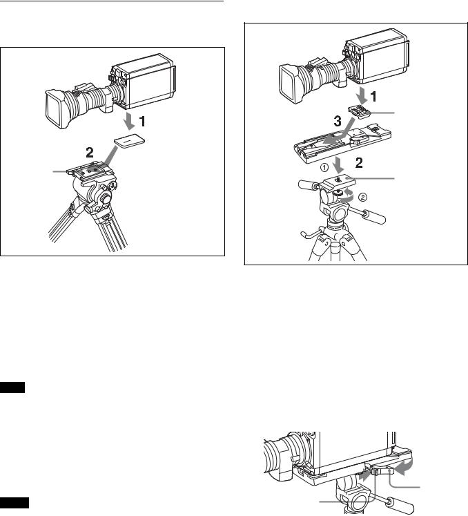
Mounting the Camera to a Tripod
When using tripod attachment adapter

 Tripod attachment adapter
Platform
1 Attach the tripod attachment adapter directly to the camera.
(Two 3/8-inch tripod screws: screw depth of 10 mm (13/ 32 inches) or less)
2 Place the camera on the tripod and mount the camera by sliding it forward along the groove of the platform until it clicks into place.
3 Move the camera back and forth, and check that it is securely fixed.
Note
If the screws of the tripod attachment adapter are 1/4-inch tripod screws, use inch conversion screws (Sony Part No.: 4-170-419-02) to attach the adapter. For details on purchasing inch conversion screws, and other information, contact a Sony service representative or Sony sales representative.
When using V shoe and tripod adapter VCT-14
Use a separately sold V shoe (Sony Part No.: A-8279-993-D) and tripod adapter VCT-14 to mount the camera to the tripod.
Notes
•Select an appropriate hole from among those at the bottom of the tripod adapter considering the balance of the weight of the camera and the tripod adapter. If an inappropriate hole is selected, the camera may fall over.
•Check that the size of the selected hole matches that of the screw of the tripod. If they do not match, the tripod adapter cannot be attached to the tripod securely.
•Use the following screws when attaching a separately sold V shoe. Attachment screws: Four Alok + K4 × 8 screws
(Sony Part No.: 3-729-072-02)
Do not use screws that are 5 mm or longer for the camera. For
details on purchasing parts, contact a Sony service representative or Sony sales representative.
V shoe
Tripod adapter
Platform
1 Attach the V shoe to the camera with the attachment screws.
2 1Attach the tripod adapter to the tripod and 2 secure it with the screw.
3 Place the camera on the tripod adapter and slide forward it along the groove of the tripod adapter until it clicks.
4 Move the camera back and forth, and check that it is securely fixed.
To remove the camera from the tripod adapter
Hold down the red button and pull the lever in the direction of the arrow.
Lever
Red button
If the pin of the tripod adapter does not return to its original position
After removing the camera, if the pin of the tripod adapter does not return to its original position, hold down the red button and move the lever in the direction of the arrow to return the pin to its original position. It is not possible to mount a camera with the pin not seated.
10
Original position
Pin
Setting the Area of Use
When using the camera for the first time
The camera is shipped with the area of use setting in an unset state. To use the camera, you need to first set the area of use.
Once the area setting is complete, set the current date and time.
For details on setting the date and time, see “Setting the Local Time” (page 11).
Note
The camera cannot be used if the area of use is not set.
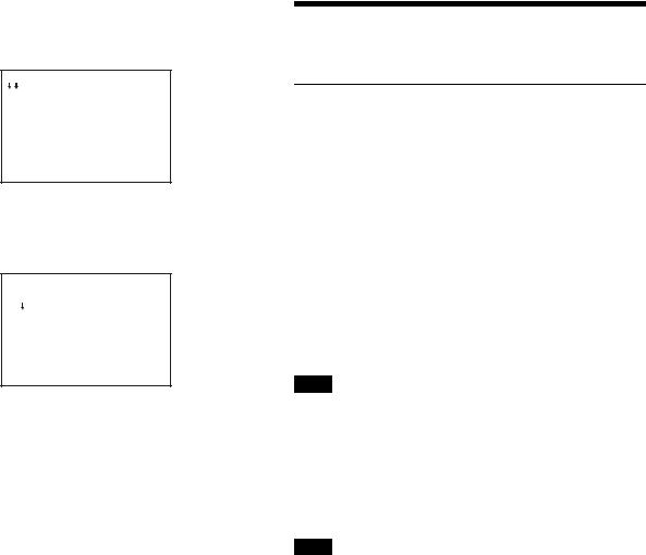
Setting the area of use
1 Turn on the camera.
The area of use setting screen appears on the monitor connected to the GL/TEST connector output or SDI 2 connector.
F O R M A T S E T T I N G
 C O U N T R Y :
 N O T S E L E C T E D
S Y S T E M L I N E : 1 0 8 0
S Y S T E M S C A N : I n t e r l a c e
S E T F O R M A T
A N D T U R N O F F O N C E . 
2 Push on the menu control knob.
The area of use becomes selectable.
F O R M A T S E T T I N G
 C O U N T R Y : ? N O T S E L E C T E D
S Y S T E M L I N E : 1 0 8 0
S Y S T E M S C A N : I n t e r l a c e
S E T F O R M A T
A N D T U R N O F F O N C E . 
3 Rotate the menu control knob to select the area of use.
Setting |
Area of use |
Output |
Systemfrequency |
value |
|
composite |
|
|
|
signal |
|
NTSC(J) |
NTSC area |
NTSC signal |
59.94i |
AREA |
(for within Japan) |
without setup |
|
|
|
|
|
NTSC |
NTSC area |
NTSC signal |
59.94i |
AREA |
(for areas other |
with setup |
|
|
than Japan) |
(7.5IRE) |
|
|
|
|
|
PAL |
PAL area |
PAL signal |
50i |
AREA |
|
|
|
|
|
|
|
4 Change the SYSTEM LINE (video resolution) and SYSTEM SCAN (video scanning mode) settings according to the video format you are using.
SYSTEM LINE
Setting value |
Resolution (horizontal x vertical) |
1080 |
1080 line (1920 x 1080) |
|
|
720 |
720 line (1280 x 720) |
|
|
SYSTEM SCAN
Setting value |
Video scanning mode |
Interlace |
Interlace |
|
|
Progressive |
Progressive |
|
|
PsF |
PsF |
|
|
Supported formats: 1080/59.94i, 1080/50i, 1080/29.97PsF, 1080/25PsF, 720/59.94P, 720/50P
5 Turn the camera off and then back on.
The camera becomes able to be used.
Changing the area of use
Change the setting in the COUNTRY item on the <OUTPUT FORMAT> page of the MAINTENANCE menu.
Note
The setting is switched to the CCU setting when a CCU is connected.
Setting the Local Time
Set the built-in clock to the current local time on the <DATE> page of the MAINTENANCE menu.
For details on menu operations, see “Menus” (page 16).
1 Turn on the camera.
2 While holding the menu control knob pressed, set the DISPLAY/MENU switch to MENU.
The camera enters Menu mode, and “TOP” is displayed at the upper-right corner of the screen.
3 Rotate the menu control knob to set the cursor to “TOP” and push on the menu control knob.
The TOP MENU screen is displayed.
<TOP MENU>
 USER
USER
USER MENU CUSTOMIZE
ALL
 OPERATION
 PAINT
PAINT
 MAINTENANCE
 FILE
FILE
 DIAGNOSIS
11
4 Rotate the menu control knob to position the cursor to MAINTENANCE and push on the menu control knob.
The CONTENTS page of the MAINTENANCE menu is displayed.
CONTENTS |
M00 TOP |
 01.<AUTO SETUP> 02.<WHITE SHADING> 03.<BLACK SHADING> 04.<AUTO IRIS> 05.<LENS>
06.<CIS COMP> 07.<TALLY> 08.<OUTPUT FORMAT> 09.<GL/TEST OUT> 10.<SDI OUT>
5 Turn the menu control knob to scroll the page and position the pointer to <DATE> then push on the menu control knob.
The <DATE> page is displayed.
<DATE> |
M13 TOP |
DATE/TIME
2015/12/23 08:32
6 Turn the menu control knob and set the date and time.
Push on the menu control knob to shift to the next digit.
7 When the date/time setting is completed, set the DISPLAY/ MENU switch to OFF to exit Menu mode.
Preparatory Settings
Configuring Control System
Connection Settings
There are the following three modes for the control system of the camera.
•LEGACY mode: This setting mode is for when controlling the camera from an external control device via the REMOTE connector of the camera.
•BRIDGE mode: This setting mode is for when controlling the camera from an external control device via the LAN connector of the camera on a one-to-one basis.
•PC CONTROL mode: This mode is for when controlling the camera from a HZC-RCP5 via a LAN cable.
Use the MAINTENANCE menu to set the mode.
For details on menu operations, see “Menus” (page 16).
Note
When the control system connection mode is changed, turn the power of all devices in the system off and then back on.
To connect in LEGACY mode
Set CNS MODE to LEGACY.
For details, see “CNS SETTINGS (MAINTENANCE menu)” (page 13).
Note
When a LAN cable will not be connected directly to the camera even when building a camera network system using a LAN, set CNS MODE to the LEGACY mode.
To connect in BRIDGE mode
1 Set CNS MODE to BRIDGE.
For details, see “CNS SETTINGS (MAINTENANCE menu)” (page 13).
2 Configure settings related to TCP/IP.
For details, see “TCP/IP SETTING (MAINTENANCE menu)” (page 13).
3 Set the LAN connection.
For details, see “LAN SETTINGS (MAINTENANCE menu)” (page 13).
4 Set the IP address of the camera for “target IP address” of the RCP to be connected to the LAN.
For details, see the operation manual of the RCP.
To connect in PC CONTROL mode
To use the camera in PC CONTROL mode, you need one PC with HZC-RCP5 (option) installed.
12
Loading...