


HT-M7
Sony HT-M7, HT-M5, HT-M3, STR-KM7, SS-MSP7M Operating Instructions Manual
...
4-415-789-11(2)
HT-M7/HT-M5/HT-M3
Home Theatre
System
Operating Instructions
2
GB
To reduce th e r i s k of fire or electric
shock, do not expose this apparatus to
rain or moisture.
To reduce the risk of fire, do not cover the
ventilation opening of the apparatus with
newspapers, tablecloths, curtains, etc.
Do not place the naked flame sources such as lighted
candles on the apparatus.
Do not install the appliance in a confined space, such
as a bookcase or built-in cabinet.
To reduce the risk of fire or electric shock, do not
expose this apparatus to dripping or splashing, and
do not place objects filled with liquids, such as
vases, on the apparatus.
As the main plug is used to disconnect the unit from
the mains, connect the unit to an easily accessible
AC outlet. Should you notice an abnormality in the
unit, disconnect the main plug from the AC outlet
immediately.
Do not expose batteries or apparatus with batteryinstalled to excessive heat such as sunshine, fire or
the like.
The unit is not disconnected from the mains as long
as it is connected to the AC outlet, even if the unit
itself has been turned off.
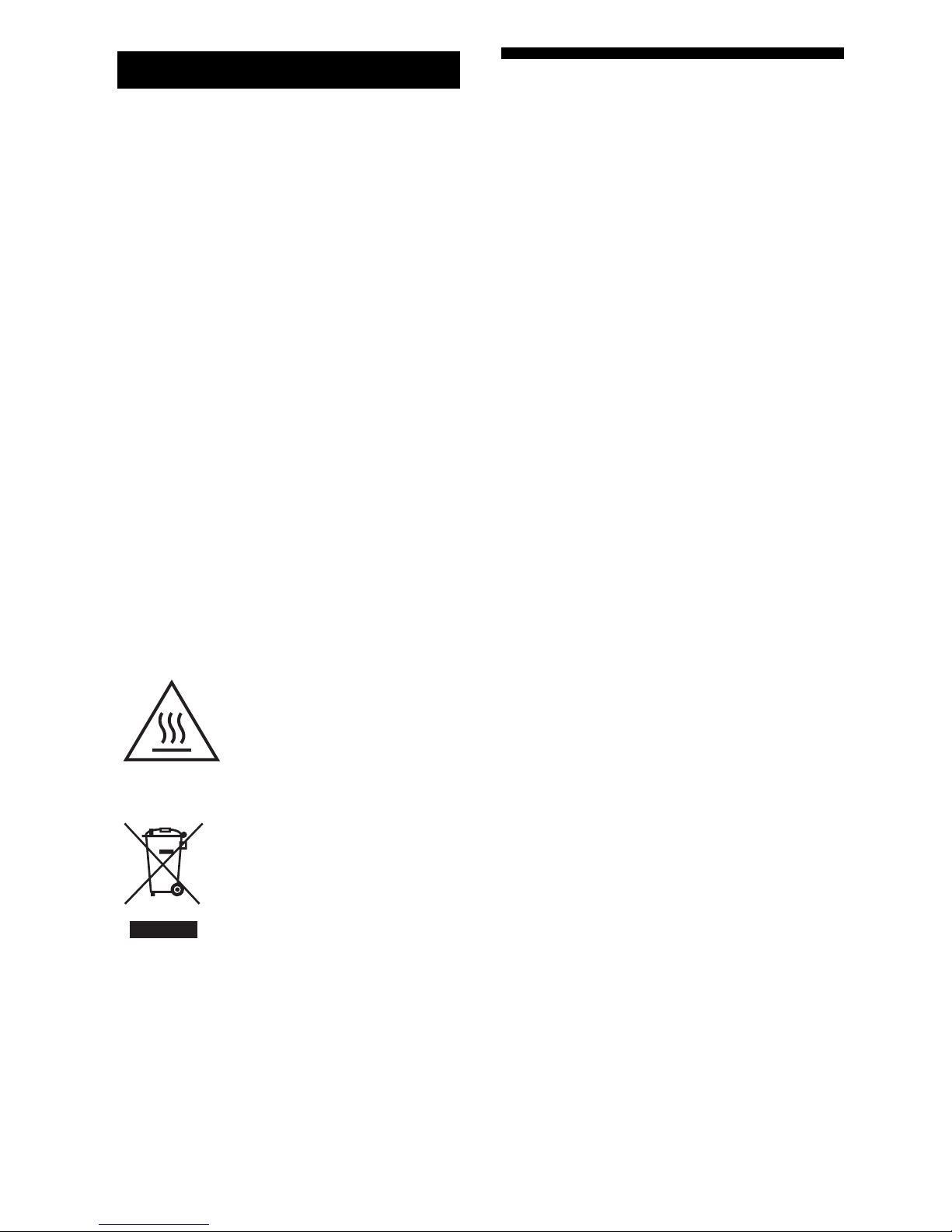
This symbol is intended to alert
the user to the presence of the Hot
Surface that may be hot if it is
touched during the normal
operation.
For customers in Australia
Disposal of Old Electrical &
Electronic Equipment
(Applicable in the European
Union and other European
countries with separate
collection systems)
About This Manual
•The instructions in this manual are for models
HT-M7, HT-M5 and HT-M3. In this manual, the
HT-M7 is used for illustration purposes unless
stated otherwise.
•The instructions in this manual describe the
operation of the receiver with the supplied remote
control. You can also use the control buttons or
knobs on the receiver if they have the same or
similar names as those on the remote control.
The HT-M7 consists of:
•Receiver STR-KM7
•Speaker system
–Front speaker SS-MSP7M (2)
–Center speaker SS-CNP7M (1)
–Surround speaker SS-MSP3M (2)
–Surround back speakerSS-SRP7M (2)
–Subwoofer SS-WP7M (2)
The HT-M5 consists of:
•Receiver STR-KM5
•Speaker system
–Front speaker SS-MSP7M (2)
–Center speaker SS-CNP7M (1)
–Surround speaker SS-SRP7M (2)
–Subwoofer SS-WP7M (2)
The HT-M3 consists of:
•Receiver STR-KM3
•Speaker system
–Front speaker SS-MSP3M (2)
–Center speaker SS-CNP7M (1)
–Surround speaker SS-SRP7M (2)
–Subwoofer SS-WP3M (2)
WARNING

3
GB
This receiver incorporates Dolby* Digital and Pro
Logic Surround and the DTS** Digital Surround
System.
*Manufactured under license from Dolby
Laboratories. Dolby, Pro Logic, and the doubleD symbol are trademarks of Dolby Laboratories.
** Manufactured under license under U.S. Patent
Nos: 5,956,674; 5,974,380; 6,226,616; 6,487,535
& other U.S. and worldwide patents issued &
pending. DTS, the Symbol, & DTS and the
Symbol together are registered trademarks &
DTS Digital Surround | 96/24 is a trademark of
DTS, Inc. Product includes software. © DTS,
Inc. All Rights Reserved.
This receiver incorporates High-Definition
Multimedia Interface (HDMI
TM
) technology.
HDMI, the HDMI Logo, and High-Definition
Multimedia Interface are trademarks or registered
trademarks of HDMI Licensing LLC in the United
States and other countries.
“x.v.Color (x.v.Colour)” and “x.v.Color
(x.v.Colour)” logo are trademarks of Sony
Corporation.
“BRAVIA” is a trademark of Sony Corporation.
“PlayStation” is a registered trademark of Sony
Computer Entertainment Inc.
MPEG Layer-3 audio coding technology and patents
licensed from Fraunhofer IIS and Thomson.
“WALKMAN” is a registered trademark of Sony
Corporation.
MICROVAULT is a trademark of Sony
Corporation.
Windows Media is either a registered trademark or
trademark of Microsoft Corporation in the United
States and/or other countries.
This product contains technology subject to certain
intellectual property rights of Microsoft. Use or
distribution of this technology outside of this
product is prohibited without the appropriate
license(s) from Microsoft.
On Copyrights

4
GB
Table of Contents
About This Manual........................................2
Supplied accessories......................................5
Description and location of parts...................6
Getting started .............................................14
Connections
1: Installing the speakers .............................15
2: Connecting the speakers..........................17
3: Connecting the TV ..................................21
4a: Connecting the video equipment ...........22
4b: Connecting the audio equipment...........27
5: Connecting the antennas (aerials)............28
Preparing the Receiver
Setting the voltage selector..........................29
Connecting the AC power cord
(mains lead) ............................................29
Initializing the receiver ................................29
Selecting surround speaker position............30
Adjusting the speaker levels and balance
(TEST TONE) ........................................30
Basic Operations
Playing an input source equipment..............31
Playing a USB device
(Except for South Africa and Argentina
models) ...................................................33
Viewing information on the display panel...35
Recording using the receiver .......................36
Tuner Operations
Listening to FM/AM radio ..........................37
Presetting FM/AM radio stations ................38
Enjoying Surround Sound
Selecting the sound field............................. 40
Resetting sound fields to the default
settings ................................................... 42
“BRAVIA” Sync Features
What is “BRAVIA” Sync? .......................... 42
Preparing for the “BRAVIA” Sync ............. 43
Playing back equipment with one-touch
operation (One-Touch Play)................... 44
Enjoying the TV sound from the speakers
connected to the receiver
(System Audio Control)......................... 44
Turning off the receiver with the TV
(System Power-Off) ............................... 45
Enjoying optimum sound field for the
selected scene (Scene Select)................. 45
Advanced Operations
Switching between digital and analog
audio (INPUT MODE) .......................... 46
Using the setting menu ............................... 46
Additional Information
Precautions.................................................. 53
Troubleshooting .......................................... 54
Specifications.............................................. 60
Index ........................................................... 63
5
GB
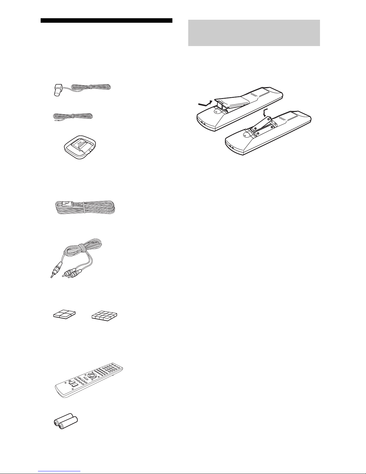
Supplied accessories
•Operating Instructions (this manual)
•Quick Setup Guide (1)
•FM wire antenna (aerial) (1)
– Mexico model only
– Other models
• AM loop antenna (aerial) (1)
• Speaker cords
– HT-M7 (
6, red/white/blue/grey/purple × 2
)
–HT-M5 (4, red/white/purple × 2)
– HT-M3 (2, red/white)
•Audio cord with stereo mini-plug (Australia
model only) (1)
•Foot pads
– Subwoofers (Big) (8)
–Speakers (Small) (12)
•Remote control (1)
– RM-AAU136 (South Africa and
Argentina models only)
– RM-AAU135 (Other models)
•R6 (size AA) batteries (2)
Insert two R6 (size AA) batteries (supplied) by
matching 3 and # on the batteries to the
diagram inside the battery compartment of the
remote control.
Notes
•Do not leave the remote control in an extremely hot
or humid place.
•Do not use a new battery with old ones.
•Do not mix manganese batteries and other kinds of
batteries.
•Do not expose the remote control sensor to direct
sunlight or lighting apparatuses. Doing so may
cause a malfunction.
•If you do not intend to use the remote control for an
extended period of time, remove the batteries to
avoid possible damage from battery leakage and
corrosion.
•When the receiver no longer responds to the
remote control, replace all the batteries with new
ones.
Inserting batteries into the
remote control
6
GB
sw
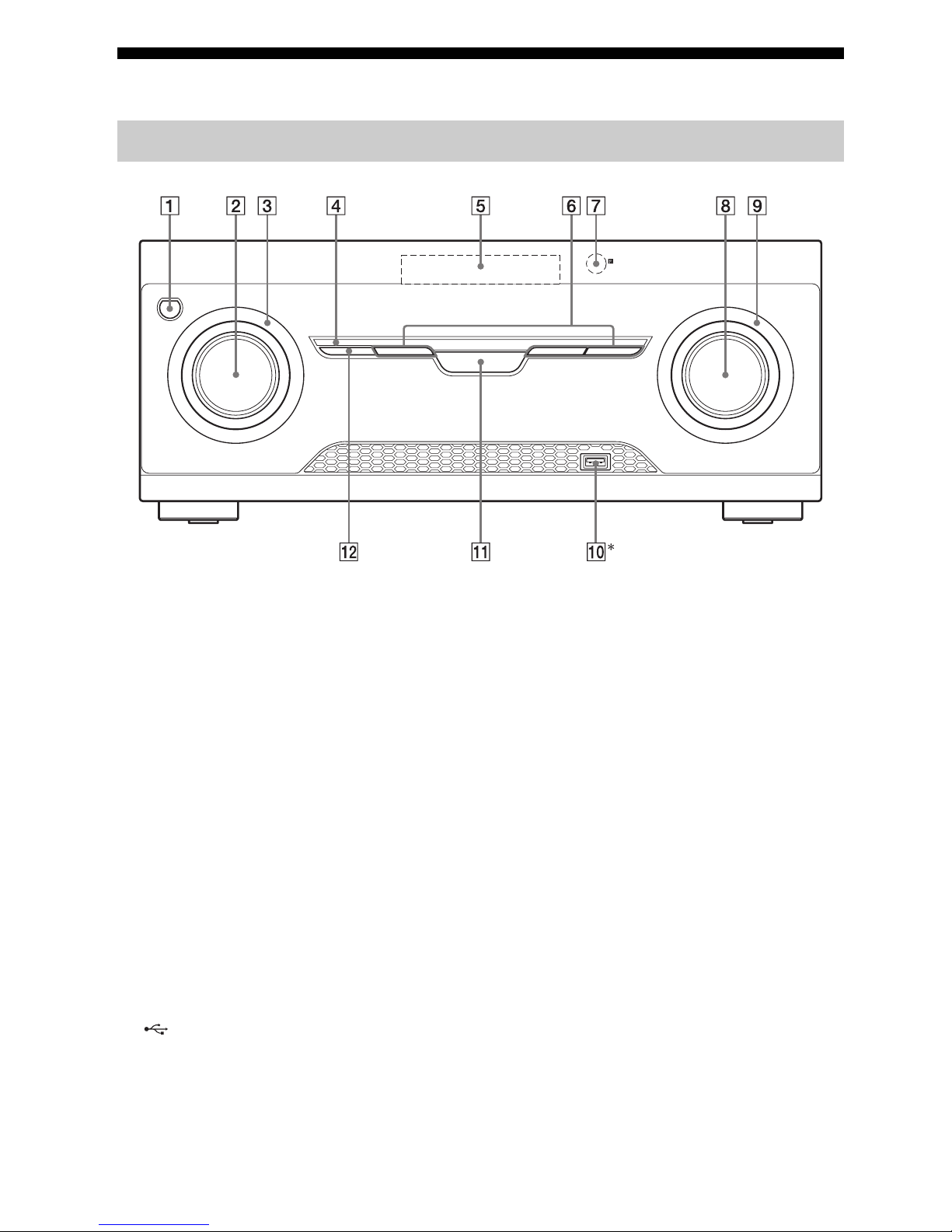
Description and location of parts
*Except for South Africa and Argentina models.
A ?/1 (on/standby) (page 29, 42)
B INPUT SELECTOR (page 31, 32, 34, 36,
37, 38, 39, 46, 55)
C INPUT SELECTOR indicator
Flashes when you turn the knob.
D M-TURBO indicator
Lights up when M-TURBO is activated.
E Display panel (page 7)
F MOVIE, MUSIC, GAMING (page 40)
G Remote control sensor
Receives signals from remote control.
H MASTER VOLUME (page 31, 32, 34)
I MASTER VOLUME indicator
Flashes when you turn the knob.
J (USB) port (page 28)
K M-TURBO
Turns the M-TURBO function on or off.
M-TURBO function reinforces the bass and
creates a more powerful sound.
L SURROUND SPEAKER (page 30)
Front panel
7
GB
Indicators on the display panel
LFE
LC
SL S
PL II
HDMI
SLEEP
D.RANGEST
COAX OPT LPCM
USB
SW
SB
SBL
R
SR
SBR
D
q
s
q
a
1324 6897q
;
DTS 96/24
5
A Playback channel indicator
The letters (L, C, R, etc.) indicate the channels
being played back. Based on the speaker
settings, the box around the letter(s) vary to
show how the receiver downmixes the source
sound.
L
R
C
SL
SR
S
SBL*
SBR*
SB*
Front Left
Front Right
Center (monaural)
Surround Left
Surround Right
Surround (monaural or the
surround equipment obtained
by Pro Logic processing)
Surround Back Left
Surround Back Right
Surround Back (the surround
back equipment obtained by
6.1 channel decoding)
B SW
Lights up when the audio signal is output from
the SUBWOOFER jack.
C
Lights up when the disc being played back
contains an LFE (Low Frequency Effect)
channel and the LFE channel signal is actually
being reproduced.
LFE
D Input indicator
Lights up to indicate the current input.
HDMI
–The INPUT MODE is set to “AUTO”, and
when the receiver recognizes the equipment
connected via an HDMI IN jack (page 46).
–The TV input detected Audio Return Channel
(ARC) signals.
COAX
The INPUT MODE is set to “AUTO” or
“COAX”, and when the source signal is a digital
signal through the COAXIAL jack (page 46).
OPT
The INPUT MODE is set to “AUTO” or
“OPT”, and when the source signal is a digital
signal through the OPTICAL jack (page 46).
E DTS indicator
Lights up the respective indicator when the
receiver is decoding the corresponding DTS
format signals.
DTS
DTS 96/24
DTS
DTS 96 kHz/24 bit
Note
When playing a DTS format disc, make sure that
you have completed the digital connections and
that INPUT MODE is not set to “ANALOG”
(page 46).
F LPCM
Lights up when the receiver is decoding the
Linear PCM signals.
G USB**
Lights up when a USB device is being played.
continued

8
GB
*HT-M7 only.
** Except for South Africa and Argentina models.
H D
Lights up when the receiver is decoding Dolby
Digital signals.
Note
When playing a Dolby Digital format disc, make
sure that you have completed the digital
connections and that INPUT MODE is not set to
“ANALOG” (page 46).
I Dolby Pro Logic indicator
Lights up the respective indicator when the
receiver performs Dolby Pro Logic processing.
This matrix surround decoding technology can
enhance input signals.
PL
PL II
Dolby Pro Logic
Dolby Pro Logic II
J Tuning indic at or
Lights up when the receiver tunes to a radio
station.
ST
Stereo broadcast
Preset station number (The number will change
according to the preset station you select.)
K D.RANGE
Lights up when dynamic range compression is
activated (page 50).
L SLEEP
Lights up when the Sleep Timer is activated
(page 13).
9
GB
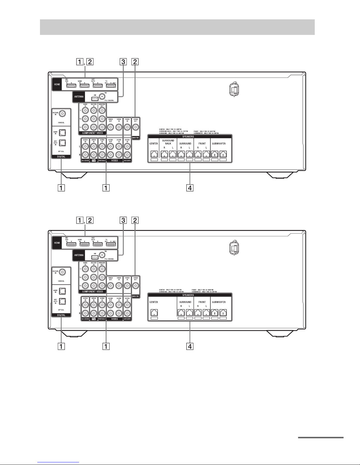
HT-M7
HT-M5
Rear panel
continued
10
GB
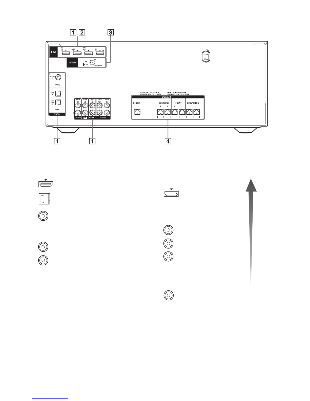
HT-M3
*You must connect the HDMI TV OUT or
MONITOR OUT (HT-M7/HT-M5 only) jack to
your TV to watch the selected input image (page
21).
** HT-M7/HT-M5 only.
A Audio signal section
DIGITAL INPUT/OUTPUT jacks (page 21, 24,
25, 26)
HDMI IN/OUT
OPTICAL IN
COAXIAL IN
ANALOG INPUT/OUTPUT jacks (page 21, 25,
27)
AUDIO IN/OUT
White (L)
Red (R)
B Video signal section*
The image quality depends on the connecting jack.
DIGITAL INPUT/OUTPUT
jacks (page 21, 24)
HDMI IN/OUT
COMPONENT VIDEO
INPUT/OUTPUT jacks** (page
21, 25)
Y, P
B, PR IN/OUT
COMPOSITE VIDEO INPUT/
OUTPUT jacks** (page 21, 25,
27)
VIDEO IN/OUT
High
quality
image
Green
(Y)
Blue
(P
B)
Red
(P
R)
Yellow

11
GB
C ANTENNA section (page 28)
FM ANTENNA jack
AM ANTENNA terminal
D SPEAKERS section (page 17, 18,
19)
12
GB
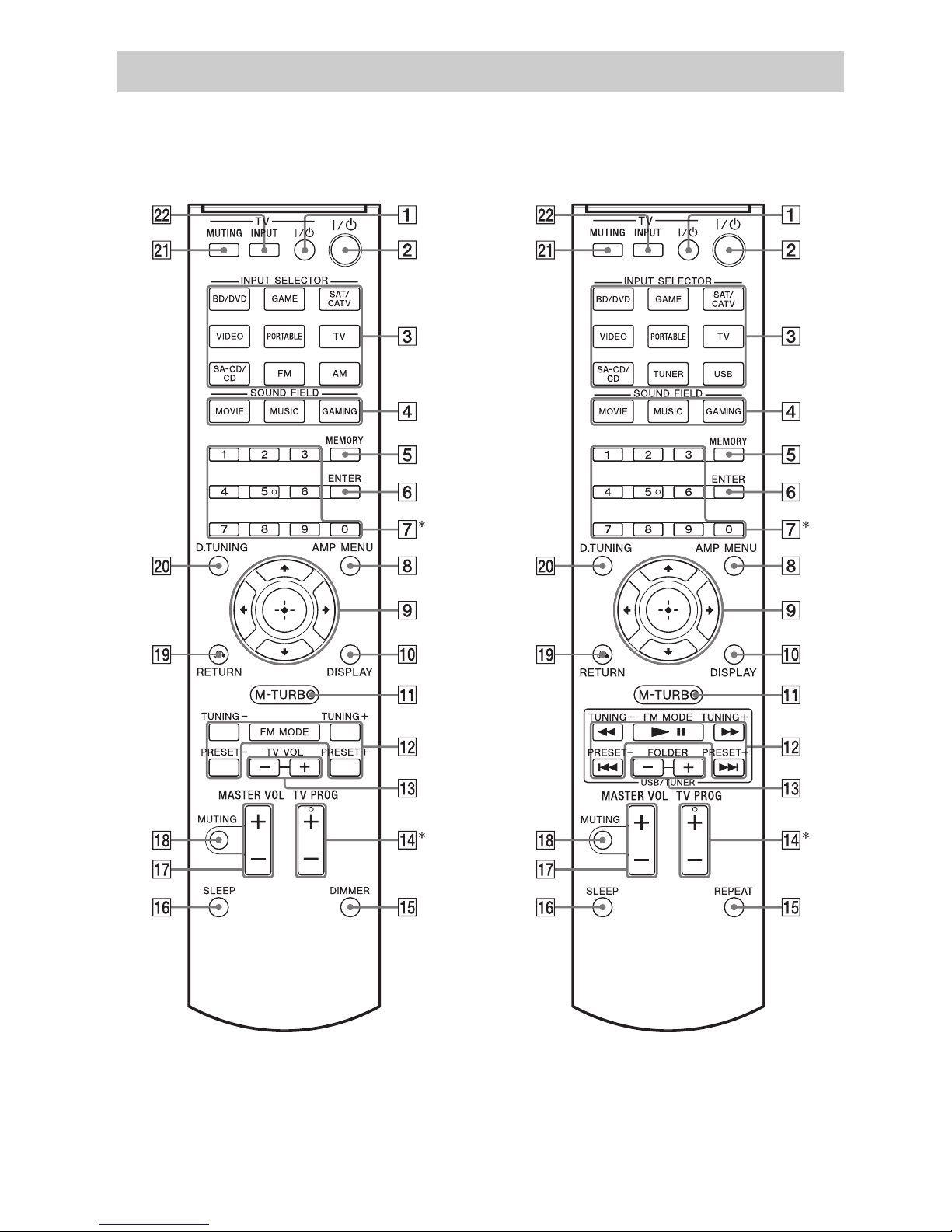
Use the supplied remote control to operate this receiver and Sony TV.
•RM-AAU136 (South Africa and
Argentina models only)
•RM-AAU135 (Other models)
*The 5 and TV PROG + buttons have tactile dots. Use the tactile dots as references when operating the
receiver.
Remote control

13
GB
To control the receiver
To con tro l a Sony TV
Note
The above explanation is intended to serve as
examples.
B ?/1 (on/standby)
Turns the receiver on or sets it to standby mode.
Saving the power in standby mode
When “CTRL.HDMI” is set to “CTRL OFF”
(page 48).
C Input buttons
Selects the equipment you want to use. When
you press any of the input buttons, the receiver
turns on.
D MOVIE, MUSIC, GAMING (page 40)
E MEMORY
Stores a station during tuner operation.
F ENTER
Enters the selections.
G Numeric buttons
Presets or tunes to the preset stations (page 38).
H AMP MENU
Displays the menu to operate the receiver.
I
Press V/v/B /b to select the settings, then press
to enter/confirm the selection.
J DISPLAY
Views information on the display panel.
K M-TURBO
Turns the M-TURBO function on or off.
M-TURBO function reinforces the bass and
creates a more powerful sound.
L m/M, NX, ./>
(RM-AAU135 only)
Operates the USB device: Backward/forward,
play/pause, skip operation.
TUNING +/–
Scans a station.
FM MODE
Selects the FM reception mode (monaural or
stereo).
PRESET +/–
Selects preset stations.
M FOLDER +/–
(RM-AAU135 only)
Selects a folder of the USB device.
O REPEAT
(RM-AAU135 only)
Plays a track or a folder repeatedly of the USB
device.
DIMMER
(RM-AAU136 only)
Adjusts the brightness of the display panel.
,
V/v/B/b
P SLEEP
Sets the receiver to turn off automatically at a
specified time.
The display changes cyclically as follows.
0-30-00 t 1-00-00 t 1-30-00 t 2-00-00 t
OFF
When Sleep Timer is being used, “SLEEP”
indicator lights up on the display panel.
Tip
To check the remaining time before the receiver
turns off, press SLEEP. The remaining time
appears on the display panel. If you press
SLEEP again, the Sleep Timer will be canceled.
Q MASTER VOL +/–
Adjusts the volume level of all speakers at the
same time.
R MUTING
Turns off the sound temporarily.
Press MUTING again to restore the sound.
S RETURN O
Returns to the previous menu.
T D.TUNING
Enters direct tuning mode.
A TV ?/1 (on/standby)
Turns the TV on or off.
M TV VOL +/–
(RM-AAU136 only)
Adjusts the TV volume.
N TV PROG +/–
Scans for the preset TV channels.
U TV MUTING
Activates the TV’s muting function.
V TV INPUT
Selects the input signal (TV or video).
14
GB
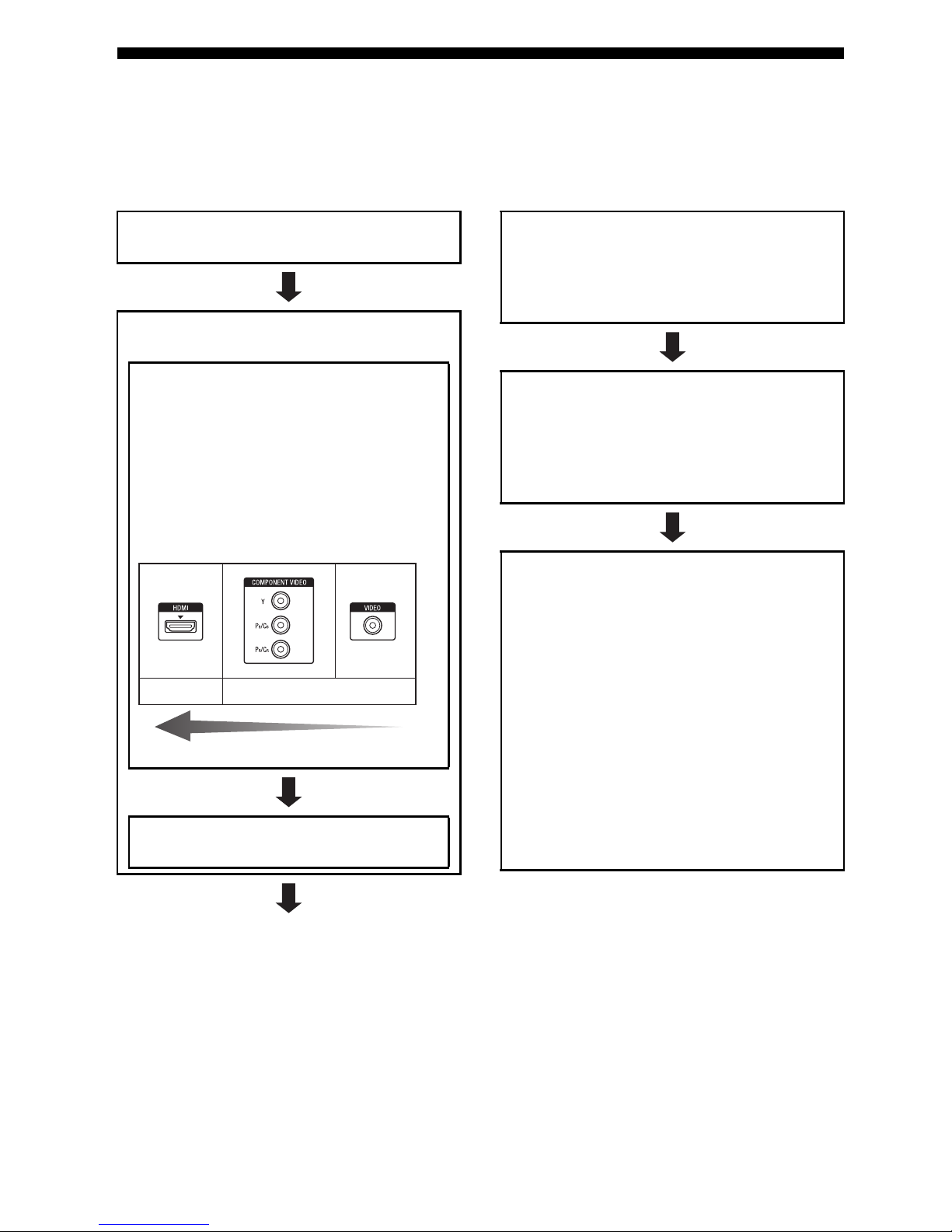
Getting started
You can enjoy your audio/video equipment connected to the receiver by following the simple steps
below.
Before connecting cords, be sure to disconnect the AC power cord (mains lead).
Installing and connecting the
speakers (page 15, 17)
Checking the connection
appropriate for your equipment
Connecting the TV and video
equipment (page 21, 22)
The image quality depends on the connecting
jack. See the illustration below. Select the
connection according to the jacks on your
equipment.
We r ec om me nd tha t yo u conn ec t your v id eo
equipment via HDMI connection if they have
HDMI jacks.
Connecting the audio equipment
(page 27)
Analog
High quality image
Digital
Preparing the receiver
See “Setting the voltage selector” (page 29),
“Connecting the AC power cord (mains lead)”
(page 29) and “Initializing the receiver” (page
29).
Setting the speakers
Select the surround speaker position (page 30),
then check the speaker connection using
“T. TONE” in LEVEL menu (page 30). If the
sound is not output correctly, check the speaker
connection.
Setting the audio output settings on
the connected equipment
To o ut put mu lti ch annel digital audio, check the
digital audio output setting on the connected
equipment.
For a Sony Blu-ray Disc player, check that “Audio
(HDMI)”, “Dolby Digital”, and “DTS” are set to
“Aut o”, “ Dolby Digi tal” and “ DTS” respe ctively
(as of September 2011).
For a PlayStation 3, check that “BD/DVD Audio
Output Format (HDMI)” and “BD Audio Output
Format (Optical Digital)” are set to “Bitstream”
(with system software version 3.70).
For details, refer to the operation instructions
supplied with the connected equipment.
15
GB
Connections
1: Installing the speakers
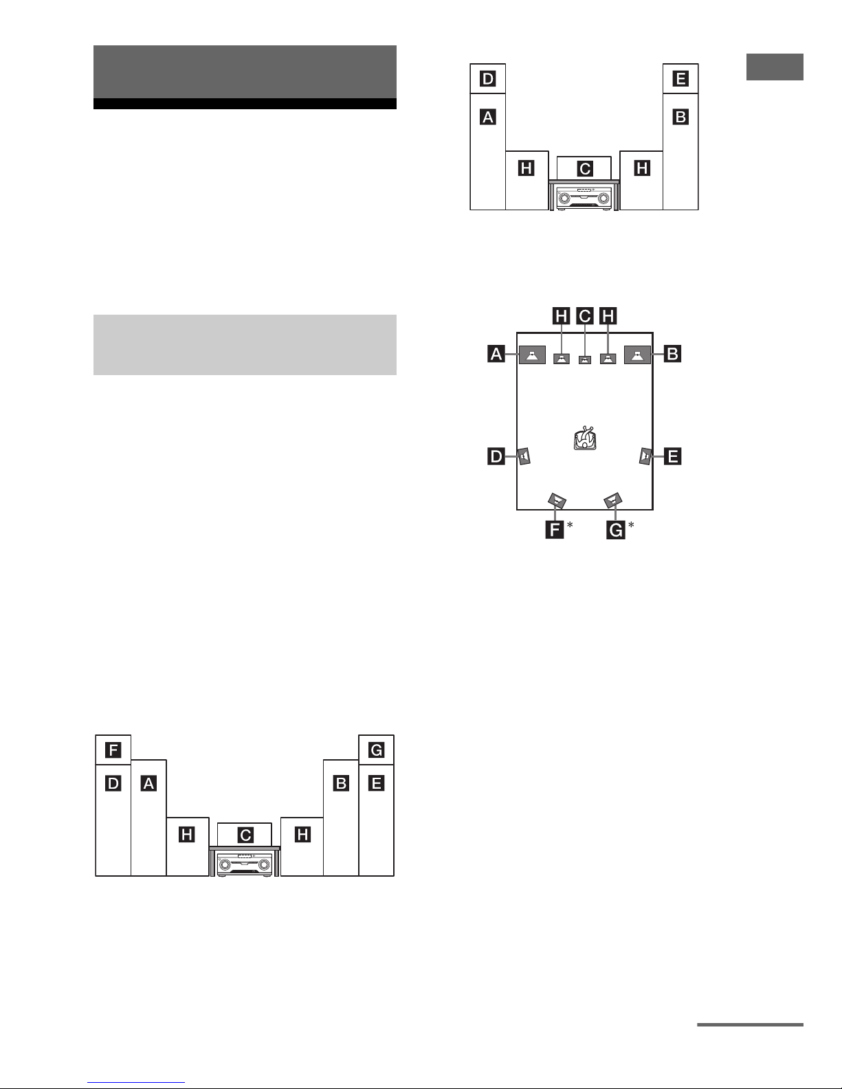
HT-M7
This receiver allows you to use a 7 channel
speaker with 2 subwoofer system.
HT-M5/HT-M3
This receiver allows you to use a 5 channel
speaker with 2 subwoofer system.
You can enjoy different sound effects from the
system by placing the speakers as shown
below.
AFront speaker (left)
BFront speaker (right)
CCenter speaker
DSurround speaker (left)
ESurround speaker (right)
FSurround back speaker (left)
GSurround back speaker (right)
HSubwoofer
Installing all the speakers in
front position
– HT-M7
– HT-M5/HT-M3
Installing the surround/
surround back speakers in rear
position
*HT-M7 only.
Notes
•Do not install the speakers on a wall.
•(HT-M7 only)
We recommend that you place the surround back
speakers on a speaker stand (not supplied).
•(HT-M5/HT-M3 only)
We recommend that you place the surround
speakers on a speaker stand (not supplied).
• For details about installing the speakers, please
refer to the supplied Quick Setup Guide.
Connections
Example of speaker system
configuration
continued
16
GB
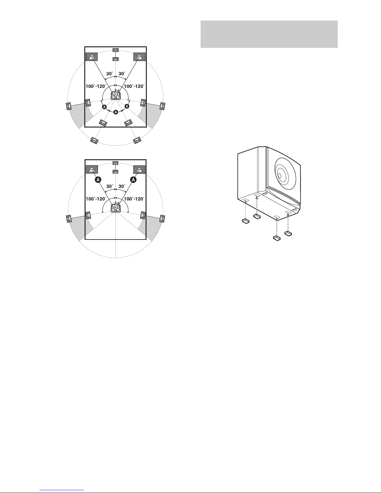
Tips
•All the angles A should be the same.
–HT-M7 only
–HT-M5/HT-M3 only
•Since the subwoofer does not emit highly
directional signals, you can place it wherever you
want.
Attach the supplied foot pads to the bottom of
the speakers and subwoofers to prevent
vibration or movement.
HT-M7:
Center speaker, surround back speakers,
subwoofers
HT-M5/HT-M3:
Center speaker, surround speakers,
subwoofers
Note
Attach the small foot pads to the center speaker,
surround speakers and surround back speakers and
the big foot pads to the subwoofers.
Installing the speakers on a flat
surface
17
GB
Connections
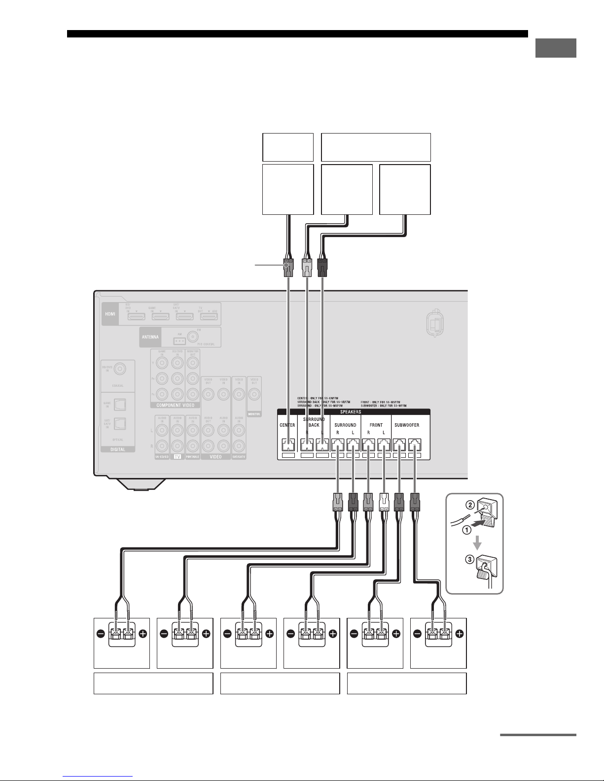
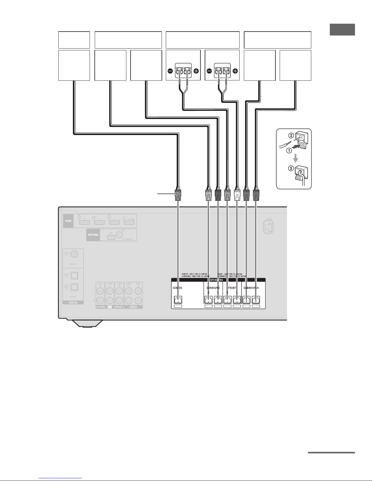
2: Connecting the speakers
Before connecting cords, be sure to disconnect the AC power cord (mains lead).
HT-M7
A Speaker cord (supplied)
Right
Center
speaker
Left
Surround speaker Front speaker Subwoofer
AA
Surround back speaker
Connector
Right Left Right Left
A
continued
18
GB
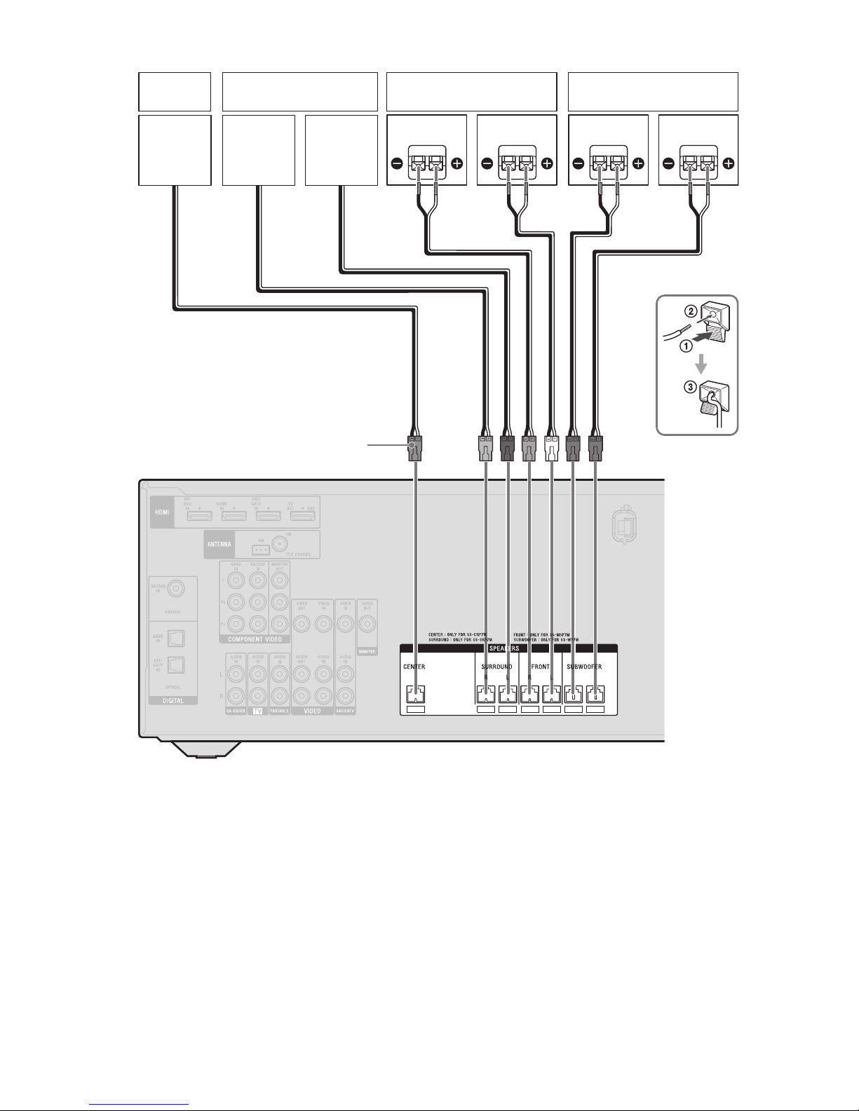
HT-M5
A Speaker cord (supplied)
Right
Center
speaker
Left
Surround speaker Front speaker Subwoofer
Connector
AA
Right Left
19
GB
Connections
HT-M3
A Speaker cord (supplied)
Connector
A
Right
Center
speaker
Left
Surround speaker Front speaker Subwoofer
Right Left
continued

20
GB
Note on speaker cords
The connector of the speaker cords are colorcoded based on the speaker type. When
connecting a speaker cord, be sure to match
the colored connector to the speaker terminal
on the receiver.
*HT-M7 only.
To connect the speakers
correctly
Check the speaker type by referring to the
speaker label* on the rear panel of the
speakers.
*The center speaker and subwoofers do not have
any character on the speaker label. For details on
the speaker type, see page 2.
** HT-M7 only.
Connector Speaker terminal
Purple SUBWOOFER
White FRONT L
Red FRONT R
Blue SURROUND L
Grey SURROUND R
Brown SURROUND BACK L
*
Tan SURROUND BACK R*
Green CENTER
Character on
speaker label
Speaker type
L Front left
R Front right
SL Surround left
SR Surround right
SBL
** Surround back left
SBR
** Surround back right
 Loading...