


4-734-401-12 (1)
HD Color Camera
Operating Instructions
Before operating the unit, please read this manual thoroughly and retain it for future reference.
HXC-FB80
© 2017 Sony Corporation

Table of Contents |
|
Overview ............................................................................. |
3 |
Camera System Components .................................................... |
3 |
System Configuration ............................................................... |
4 |
Name and Function of Parts.............................................. |
9 |
Front and Left Side ................................................................... |
9 |
Front and Right Side ............................................................... |
11 |
Rear ......................................................................................... |
13 |
Lens (supplied with the HXC-FB80K/HXC-FB80S) ............. |
14 |
Viewfinder .............................................................................. |
15 |
Connection and Setup ...................................................... |
16 |
Connecting to a Camera Control Unit..................................... |
16 |
AC Power Supply (Standalone Operation) ............................. |
17 |
Attaching and Adjusting the Viewfinder ................................ |
18 |
Attaching the V-Wedge Shoe Attachment.............................. |
21 |
Using the Camera for the First Time ...................................... |
21 |
Attaching and Adjusting the Lens........................................... |
23 |
Preparing the Audio Input....................................................... |
24 |
Mounting on a Tripod ............................................................. |
25 |
Attaching the Shoulder Strap .................................................. |
26 |
Adjusting the Shoulder Pad Position ...................................... |
27 |
Shooting............................................................................. |
27 |
Basic Procedure for Shooting ................................................. |
27 |
Adjustments and Settings ................................................ |
28 |
Changing the Video Format.................................................... |
28 |
Adjusting the Black Balance and White Balance ................... |
28 |
Setting the Electronic Shutter ................................................. |
30 |
Setting Automatic Iris ............................................................. |
31 |
Setting the TLCS Function ..................................................... |
31 |
Setting the Focus Assist Function........................................... |
31 |
Setting the Camera Outputs .................................................... |
32 |
Adjusting the Audio Level...................................................... |
33 |
Setting the Digital Extender Function..................................... |
33 |
Menu Operation ............................................................... |
34 |
Viewfinder Display Screen ..................................................... |
34 |
Operating the Menu ................................................................ |
35 |
Selecting a Page ...................................................................... |
36 |
Setting Menu Items ................................................................. |
36 |
Editing the USER Menu ......................................................... |
37 |
Hiding the TOP MENU Screen .............................................. |
39 |
Menu List .......................................................................... |
41 |
Menu Tree ............................................................................... |
41 |
OPERATION Menu................................................................ |
46 |
PAINT Menu........................................................................... |
53 |
MAINTENANCE Menu ......................................................... |
57 |
FILE Menu.............................................................................. |
62 |
DIAGNOSIS Menu................................................................. |
63 |
Appendix ........................................................................... |
65 |
Usage Precautions ................................................................... |
65 |
Cleaning the Viewfinder ......................................................... |
65 |
Error Messages........................................................................ |
66 |
Supported USB Flash Drives .................................................. |
66 |
Specifications .......................................................................... |
67 |
Pin Assignment ....................................................................... |
68 |
Open Software Licenses.......................................................... |
70 |
2
Overview
The HXC-FB80 HD Color Camera employs a 2/3-inch type “Exmor” CMOS image sensor that achieves a high sensitivity of F12 (1080/ 59.94i)/F13 (1080/50i) and high S/N ratio of 60 dB. Full HD progressive is also supported at 59.94/50P frame rates.
You can use this unit as a studio camera by connecting it to an HXCU-FB80 or HXCU-FB70 Camera Control Unit (CCU) using a fiber cable. 4K (3840×2160) upscaled signal output or HD-HDR signal (HLG) output from the HXCU-FB80 is supported when used in conjunction with the HXCU-FB80.
Note
The version of the unit and the HXCU-FB80 to connect to the unit must both be upgraded to version 1.10 or later for HD-HDR signal support. For details, contact a Sony sales or service representative.
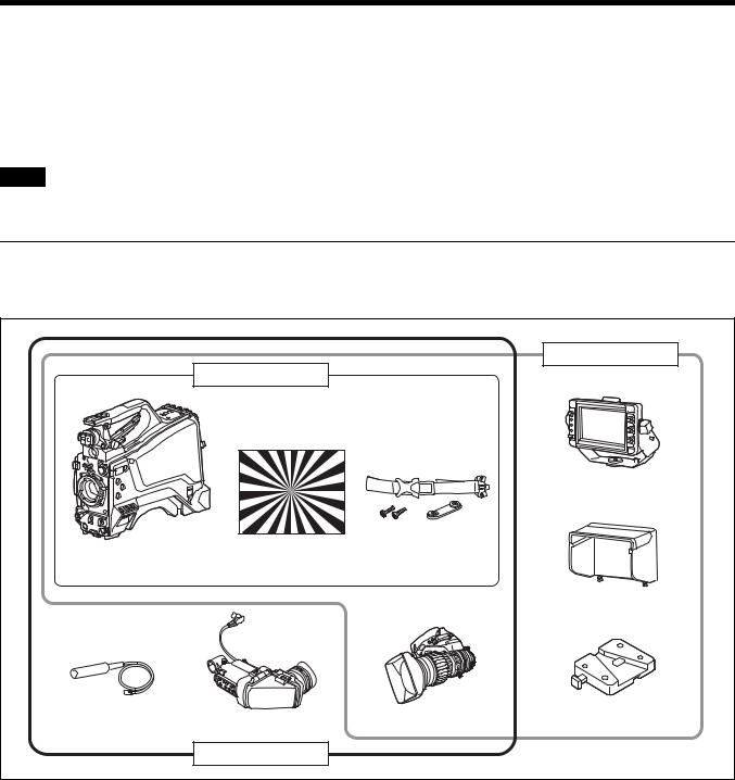
Camera System Components
The HXC-FB80 camera system comprises the components shown in the figure below.
The operation of the camera head is the same for all models.
|
|
|
HXC-FB80S |
|
|
HXC-FB80H |
|
|
|
|
|
|
HDVF-L750 |
|
|
|
|
Viewfinder |
|
HXC-FB80 camera head |
Test chart for flange |
Cable clamp belt |
|
|
focal length |
|
|||
|
|
|
||
|
adjustment |
|
|
|
|
|
|
Indoor hood |
|
Microphone |
|
Lens |
V-wedge shoe |
|
HDVF-L10 |
attachment |
|||
|
|
|||
|
Viewfinder |
|
|
|
|
HXC-FB80K |
|
|
3
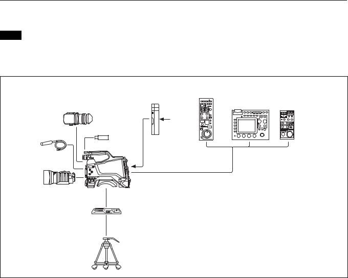
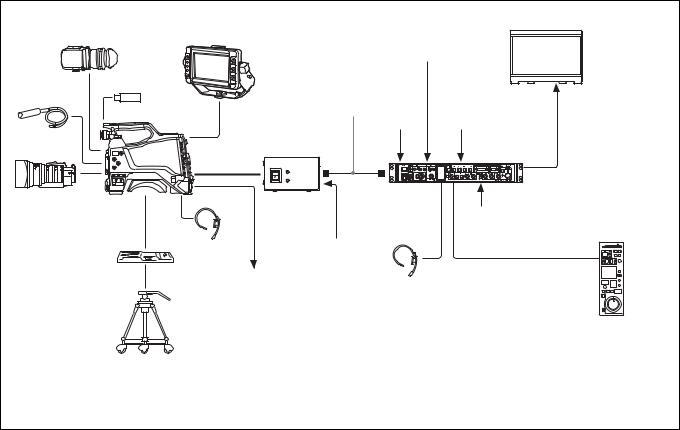
System Configuration
Peripherals and related devices for the camera are shown in the figures.
Note
Production of some of the peripherals and related devices shown in the figures may have been discontinued. For advice on choosing devices, please contact your Sony dealer or a Sony service representative.
Standalone operation example
|
|
RCP-1000 series |
|
AC-DN10 |
Remote Control Panel |
|
RM-B750/B170 |
|
HDVF-L10 |
AC Adaptor |
|
|
Remote Control Unit |
|
Viewfinder |
|
|
|
|
AC power
USB flash drive
Microphone
HXC-FB80
Lens
CCA-5 cable
 Sync signal input
  3G-SDI/HD-SDI/SD-SDI/VBS video output a) b)
VCT-14/U14
Tripod Adaptor
Tripod for portable camera
a)No subcarrier phase-lock function with respect to external reference is available for the VBS signal output from the camera.
b)SD-SDI and VBS output are not available when OUTPUT FORMAT is set to HDR.
4

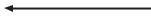
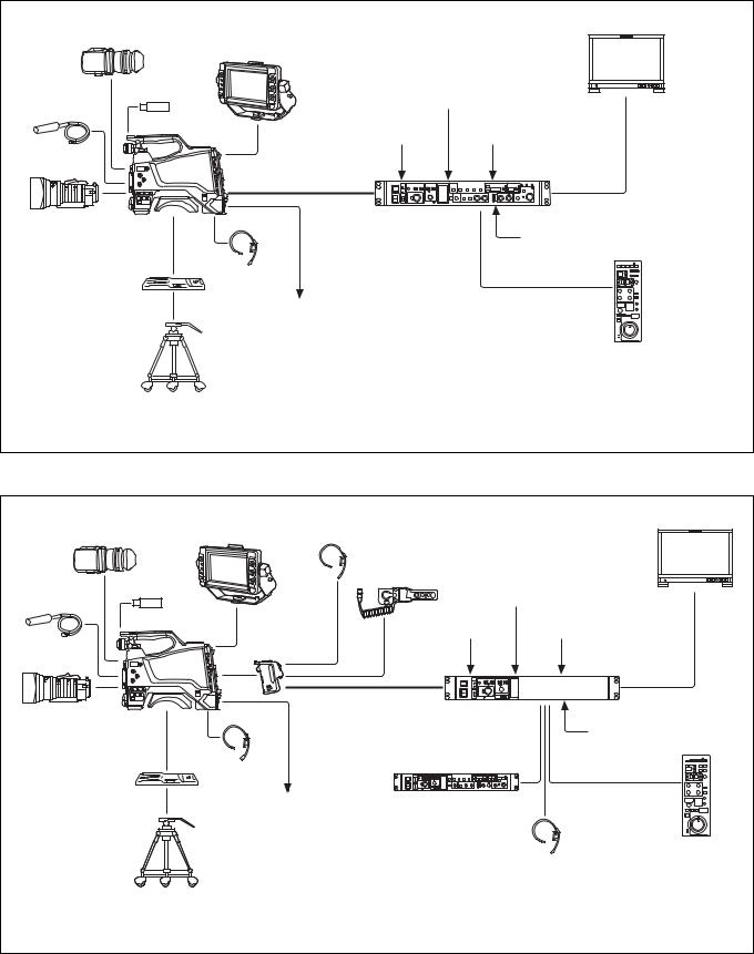
4K SDR and HD SDR signal operation (connection with HXCU-FB80)
HDVF-L10
Viewfinder
USB flash drive
Microphone
HXC-FB80
Lens
VCT-14/U14
Tripod Adaptor
Tripod for portable camera
|
|
|
4K compatible |
Picture |
||
|
|
|
picture monitor |
monitor |
||
HDVF-L750 |
Return video |
|
|
|
|
|
Viewfinder |
|
|
|
|
||
input |
|
|
|
|
|
|
|
|
|
|
|
|
|
|
|
VBS prompter |
|
|
|
|
|
|
video input |
|
|
|
|
|
Sync signal |
HD prompter |
SLOT2: 4K/ |
SLOT1: HD |
||
|
12G, 4K/3G, |
SDI/SD SDI |
||||
|
input |
video input |
|
|||
|
|
or 2K/3G |
|
video output |
||
|
|
|
|
|
||
Optoelectric |
|
|
|
video output b) |
|
|
composite cable a) |
|
|
|
|
|
|
|
HXCU-FB80 |
|
|
|
|
|
|
4K/HD Camera |
AC power |
|
|
|
|
|
Control Unit |
|
|
|
|
|
|
|
|
|
|
|
|
Intercom |
|
CCA-5 cable/LAN cable c) |
|
|
|
|
headset |
|
|
|
|
|
|
Prompter video |
|
|
|
|
|
|
output |
Intercom |
RCP-1000-series |
|
|
||
headset |
|
|
||||
|
Remote Control Panel |
|
|
|||
|
|
|
|
|||
a)The maximum transmission distance is approximately 600 m (1,150 ft) when using Sony CCFN-25/50/100/ 150/200/250 Hybrid Fiber Cable (with camera head + portable lens + HDVF-L750).
b)4K/3G output and 2K/3G output are not supported at the same time.
c)A LAN cable can be used only to connect the RCP-1500/1501/1530. To connect it, power needs to be supplied via a PoE hub or power needs to be supplied to the EXT DC IN connector of the RCP-1500/1501/1530.
When sub camera is connected (connection with HXCU-FB80)
HXC-P70 etc. |
|
|
HD picture |
Picture |
sub camera |
Intercom |
|
||
|
monitor |
monitor |
||
CCA-5 cable |
headset |
|
||
Return video |
|
|
||
|
|
|
|
|
HD SDI OUT |
|
input |
|
|
AC-DN10 |
|
VBS |
|
|
|
prompter |
|
|
|
AC Adaptor |
|
|
|
|
|
video input |
|
|
|
|
|
|
|
|
|
Sync signal |
HD prompter |
SLOT2: |
SLOT1: |
|
input |
HD TRUNK HD SDI/ |
||
HD TRUNK |
|
video input |
video |
SD SDI video |
Optical |
|
output b) |
output |
|
IN b) |
|
|||
|
composite |
|
|
|
|
cable a) |
|
|
|
|
HXCU-FB80 |
|
|
|
HXC-FB80 |
4K/HD Camera |
D-Sub n 8 pin d) |
||
Control Unit |
AC power |
|||
|
CCA-5 cable/LAN |
|
cable c) |
Prompter video output |
|
Intercom headset |
RCP-1000-series |
|
|
|
Remote Control Panel |
a)The maximum transmission distance is 600 m (1,970 ft) when Sony CCFN-25/50/100/150/200/250 Hybrid Fiber Cable is used.
b)Operation supported when the signal format is not set to 1080/50P, 59.94P.
c)LAN cable connection is supported only for RCP-1500/1501/1530. Power must be supplied via a PoE hub or power supply must be connected to EXT DC IN connector of RCP-1500/1501/1530.
d)For details about a D-Sub remote adapter, contact a Sony service representative.
5
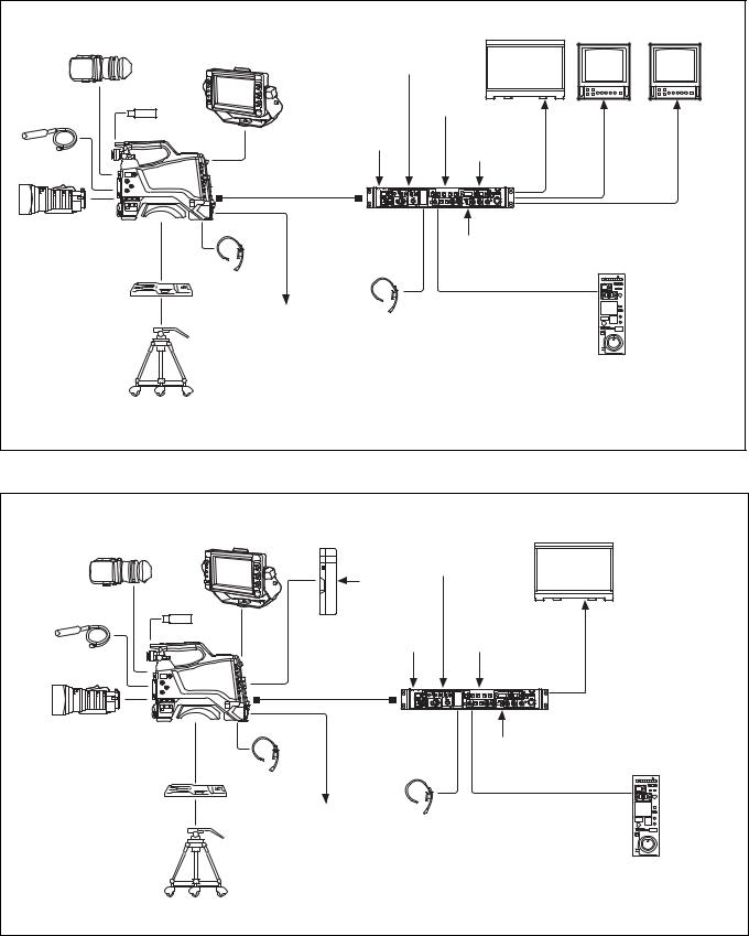
HD HDR and HD SDR signal operation (connection with HXCU-FB80)
HDVF-L10
Viewfinder HDVF-L750
Viewfinder
HD HDR compatible |
HD picture |
Picture |
picture monitor |
monitor |
monitor |
Return video input
USB flash drive
Microphone
HXC-FB80
Lens
VCT-14/U14
Tripod Adaptor
Tripod for portable camera
Sync signal input
Optoelectric composite cable a)
HXCU-FB80
4K/HD Camera
Control Unit
Intercom headset
Prompter video
output Intercom headset
VBS prompter video input
HD prompter video input
AC power
SLOT2: |
SLOT2: |
SLOT1: |
HD HDR |
HD SDR or |
HD SDI/ |
video |
HD TRUNK |
SD SDI |
output |
video |
video |
|
output b) |
output |
CCA-5 cable/LAN cable c)
RCP-1000-series
Remote Control Panel
a)The maximum transmission distance is approximately 600 m (1,150 ft) when using Sony CCFN-25/50/100/ 150/200/250 Hybrid Fiber Cable (with camera head + portable lens + HDVF-L750).
b)HD TRUNK output supported when the signal format is set to 1080/50i HDR, 59.94i HDR.
c)A LAN cable can be used only to connect the RCP-1500/1501/1530. To connect it, power needs to be supplied via a PoE hub or power needs to be supplied to the EXT DC IN connector of the RCP-1500/1501/1530.
System operation example: When connected using single-mode optical fiber cables
HDVF-L10 |
HDVF-L750 |
AC-DN10 |
|
Picture monitor |
Viewfinder |
AC Adaptor |
|
||
|
|
|||
Viewfinder |
|
|
||
|
Return |
|
||
|
|
|
||
|
|
video input |
|
|
|
USB flash |
AC power |
|
|
|
|
|
|
|
Microphone |
drive |
|
|
Video |
|
|
|
||
|
|
Sync signal |
VBS prompter |
|
|
HXC-FB80 |
output |
||
|
input |
video input |
||
|
|
|
||
Lens |
|
Single-mode optical |
|
|
|
|
fiber cables (pair) a) |
|
|
VCT-14/U14
Tripod Adaptor
Tripod for portable camera
|
HXCU-FB80 |
|
|
|
4K/HD Camera |
AC power |
|
|
Control Unit |
||
|
|
||
Intercom |
|
CCA-5 cable/LAN cable b) |
|
headset |
|
|
|
Prompter video |
Intercom |
RCP-1000-series |
|
output |
|||
Remote Control Panel |
|||
|
headset |
||
|
|
a)The maximum transmission distance is approximately 10 km (6 miles) when using general-purpose single-mode fiber cables with LC connectors.
b)A LAN cable can be used only to connect the RCP-1500/1501/1530. To connect it, power needs to be supplied via a PoE hub or power needs to be supplied to the EXT DC IN connector of the RCP-1500/ 1501/1530.
6
System operation example: When connected with HXCE-FB70 Power Supply Unit
HDVF-L10 |
HDVF-L750 |
|
|
|
Picture monitor |
Viewfinder |
Viewfinder |
|
Return video |
|
|
|
|
|
|
||
|
|
|
input |
|
|
USB flash drive |
|
Single-mode |
|
|
|
Microphone |
|
optical fiber |
|
Video |
|
HXC-FB80 |
|
cable b) |
Sync signal |
VBS prompter |
output |
|
|
|
input |
video input |
|
Lens |
Optoelectric |
|
|
|
|
composite |
|
|
|
|
|
|
|
|
|
|
|
|
cable a) |
|
|
|
|
|
|
HXCE-FB70 |
HXCU-FB80 |
|
|
|
|
4K/HD Camera |
|
|
|
|
|
Power Supply |
Control Unit |
AC power |
|
|
|
Unit |
|
|
|
VCT-14/U14 |
Intercom |
AC power |
|
CCA-5 cable/LAN cable c) |
|
headset |
|
|
|
|
|
Tripod Adaptor |
|
|
|
|
|
|
|
|
|
|
|
|
Prompter video |
Intercom |
|
RCP-1000 series |
|
|
output |
|
Remote Control Panel |
||
|
|
|
|||
headset
Tripod for portable camera
a) The maximum transmission distance is approximately 350 m (1,150 ft) when using Sony CCFN-25/50/ 100/150/200/250 Hybrid Fiber Cable (with camera head + portable lens).
b)The maximum transmission distance is approximately 10 km (6 miles) when using general-purpose single-mode fiber cables with LC connectors.
c)A LAN cable can be used only to connect the RCP-1500/1501/1530. To connect it, power needs to be supplied via a PoE hub or power needs to be supplied to the EXT DC IN connector of the RCP-1500/ 1501/1530.
7
System operation example: When connected using an optoelectric composite cable (connection with HXCU-FB70)
HDVF-L10 |
|
|
Picture monitor |
Viewfinder |
|
HDVF-L750 |
|
|
|
Viewfinder |
|
|
USB flash drive |
Return video input |
|
Microphone |
|
||
|
|
|
|
|
HXC-FB80 |
Sync signal input |
Prompter video input |
|
|
||
Lens |
|
Optoelectric |
|
|
|
composite cable a) |
|
|
|
HXCU-FB70 |
HD-SDI/SD-SDI/VBS/HDMI |
|
|
video output |
|
|
|
HD Camera Control Unit |
AC power |
|
|
|
|
CCA-5 cable /
VCT-14/U14 Intercom LAN cable b) headset
Tripod Adaptor
Prompter video output
Tripod for portable
camera RCP-1000 series Remote Control Panel
a) The maximum transmission distance is approximately 350 m (1,150 ft) when using Sony CCFN-25/50/100/ 150/200/250 Hybrid Fiber Cable (with camera head + portable lens + HDVF-L750).
b)A LAN cable can be used only to connect the RCP-1500/1501/1530. To connect it, power needs to be supplied via a PoE hub or power needs to be supplied to the EXT DC IN connector of the RCP-1500/1501/1530.
System operation example: When connected using a triaxial cable
HDVF-L10 |
HDVF-L750 |
|
|
|
Picture monitor |
|
Intercom headset |
|
|
||||
Viewfinder |
Viewfinder |
|
|
|
||
|
|
|
|
CAC-6 |
|
|
USB flash drive |
|
|
Return Video Selector |
|
|
|
|
|
Return video input |
|
|||
Microphone |
|
|
|
|
||
|
|
|
|
|
|
|
|
HXC-FB80 |
CA-TX70 |
|
Sync signal input |
Prompter video input |
|
|
|
|
||||
|
|
HD Camera |
||||
|
|
|
|
|
||
Lens |
|
Adaptor |
|
|
|
|
|
|
|
|
|
|
|
|
|
|
Triaxial cable a) |
|
HD-SDI/SD-SDI/VBS |
|
|
|
|
|
HXCU-TX70 |
|
video output |
|
|
|
|
HD Camera Control Unit |
AC power |
|
|
|
|
|
|
||
|
|
|
|
|
CCA-5 cable / |
|
VCT-14/U14 |
Intercom |
|
|
LAN cable b) |
|
|
headset |
|
|
|
|
|
|
Tripod Adaptor |
|
|
|
|
|
|
|
|
|
|
|
|
|
|
Prompter video output |
HKCU-FP2 |
|
|
||
|
|
|
|
Front Control Panel |
|
|
Tripod for portable |
|
|
|
(Attach to front of HXCU-TX70) |
|
|
|
|
|
|
|
|
|
camera |
|
|
|
|
|
RCP-1000 series |
|
|
|
|
Intercom headset |
Remote Control Panel |
|
a)For details about transmission distance, refer to the operating instructions for the HXCU-TX70 HD Camera Control Unit.
b)A LAN cable can be used only to connect the RCP-1500/1501/1530. To connect it, power needs to be supplied via a PoE hub or power needs to be supplied to the EXT DC IN connector of the RCP-1500/1501/1530.
8

Name and Function of Parts
Front and Left Side
For the pin assignment of each connector, see “Pin Assignment” (page 68).
a V-wedge shoe attachment
Attach to a HDVF-L750/HDVF-L770/HDVF-EL75 viewfinder. To attach a viewfinder, attach the V-wedge shoe here.
For details about V-wedge shoe attachment, see “Attaching the V- Wedge Shoe Attachment” (page 21).
b Cable clamp attachment
For details about attaching, see “Attaching the cable clamp belt” (page 16).
c Shoulder strap fitting
For details about attaching, see “Attaching the Shoulder Strap” (page 26).
d Microphone holder attachment
For details about attaching, see “Attaching the microphone holder” (page 25).
e Cable clamp
Clamp the lens cable and microphone cable.
f  (USB) connector
For details about how to use a USB flash drive and compatible USB flash drives, see “Supported USB Flash Drives” (page 66).
g Viewfinder front-to-back positioning lock knob
Loosen this knob to adjust the front-to-back position of the viewfinder.
h VF (viewfinder) connector (20-pin, round)
Connect the viewfinder cable.
i Viewfinder left-to-right positioning ring
Adjusts the left-to-right position of the viewfinder attached to the viewfinder shoe. Loosen the ring to adjust the viewfinder position, then return the ring to the original position to secure the viewfinder.
9

j 1/4-inch screw-type accessory shoe
k Slide-type accessory shoe
l Viewfinder front-to-back positioning lever
Adjusts the front-to-back position of the viewfinder attached to the viewfinder shoe. Loosen the lever to adjust the viewfinder position, then return the lever to the original position to secure the viewfinder.
m Viewfinder shoe
Attach the HDVF-L10 viewfinder supplied with the HXC-FB80K.
For details about attaching, see “Attaching and Adjusting the Viewfinder” (page 18).
n Lens mount securing rubber
After locking the lens in position using the lens locking lever, fit this rubber over the lower of the two projections. This secures the lens mount, preventing it from coming loose.
o Lens mount (special bayonet mount)
Attach a lens.
Consult your Sony dealer or a Sony service representative for information about available lenses.
For details about attaching, see “Attaching and Adjusting the Lens” (page 23).
pCCU (Camera Control Unit) connector (optoelectric composite connector)
Connect to the HXCU-FB80 4K/HD Camera Control Unit. When connected with an optoelectric composite cable, all the
signals of the camera, comprising the power supply, control signals, video signals, and audio signals, can be transmitted/received with the one optoelectric composite cable.
When connected with a pair of single-mode fiber cables, all the signals except the power supply can be transmitted/received with the pair of single-mode fiber cables.
q TRUNK connector (D-sub 9-pin)
Use as the trunk signal (RS-232C) input/output connector when connected with the HXCU-FB80.
It features an assignable pin that can be used, when connected using a dedicated cable, for a function assigned on the <EXT I/O> page in the MAINTENANCE menu.
r Shoulder pad
Raise the shoulder pad fixing lever to adjust the position in the front- to-rear direction. Adjust the position for maximum convenience when operating the camera on your shoulder.
For details about adjusting the position, see “Adjusting the Shoulder Pad Position” (page 27).
s LENS connector (12-pin)
Connect the lens cable.
Note
When connecting/disconnecting the lens cable, power off the camera first.
tAUDIO 1 IN (audio input 1) connector (XLR type, 3-pin, female)
Connect to audio equipment or a microphone.
When the camera is connected to an HXCU-FB80, the input signal will be output from the AUDIO OUTPUT CH-1 connector. You can configure the camera so that the audio is embedded in the output from the SDI output (MIC1) on the <SDI OUT> page in the MAINTENANCE menu.
For details about connecting the microphone supplied with the HXC-FB80K, see “Connecting a microphone to the AUDIO 1 IN connector” (page 24).
u Audio input 1 selector switch
Select the audio level input to the AUDIO 1 IN connector.
+48V: To supply +48 V phantom power to condenser microphones MIC: When a microphone-level input is connected
LINE: When a line-level (0 dBu) signal source is connected Select +48V when using the microphone supplied with the HXCFB80K.
v Tripod mount
For details about attaching, see “Mounting on a Tripod” (page 25).
w Lens locking lever
After inserting the lens in the lens mount, rotate the lens mount ring with this lever to lock the lens in position.
After locking the lens, be sure to use the lens mount securing rubber to prevent the lens from becoming detached.
x Lens mount cap
Remove by raising the lens locking lever. When no lens is mounted, keep this cap fitted for protection from dust.
10
Front and Right Side
Note |
|
|
|
|
|
|
|
|
|
|
|
|
When connected to a camera control unit or external remote control device |
• |
SHUTTER switch |
||||||||||
(for example, RCP or RM), the following switch functions are controlled |
• |
WHT/BLK switch |
||||||||||
from the connected device. The switches on the camera do not function. |
• |
OUTPUT/AUTO KNEE switch |
||||||||||
|
|
|
|
|
|
|
|
|
|
• |
WHITE BAL switch |
|
|
|
|
|
|
|
|
|
|
|
• |
GAIN switch |
|
|
|
|
|
|
|
|
|
|
|
|
|
|
|
|
|
|
|
|
|
|
|
|
|
|
|
|
|
|
|
|
|
|
|
|
|
|
|
|
|
|
|
|
|
|
|
|
|
|
|
|
|
|
|
|
|
|
|
|
|
|
|
|
|
|
|
|
|
|
|
|
|
|
|
|
|
|
|
|
|
|
|
|
|
|
|
|
|
|
|
|
|
|
|
|
|
|
|
|
|
|
|
|
|
|
|
|
|
|
|
|
|
|
|
|
|
|
|
|
|
|
|
|
|
|
|
|
|
|
|
|
|
|
|
|
|
|
|
|
|
|
|
|
|
|
|
|
|
|
|
|
|
|
|
|
|
|
|
|
|
|
|
|
|
|
|
|
|
|
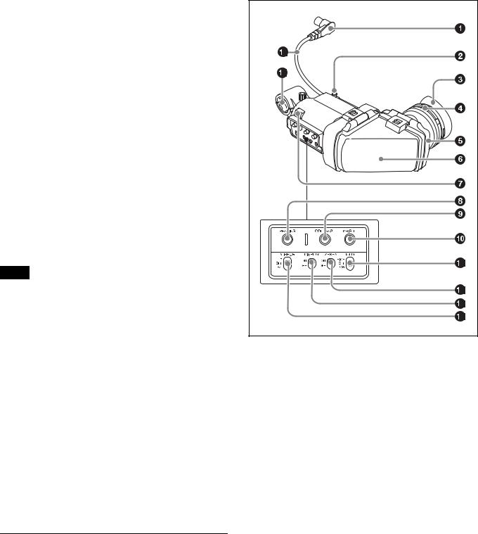
a FILTER (filter select) knob
Switch between four built-in ND filters. When this switch is adjusted, the filter setting appears in the viewfinder for about three seconds.
FILTER knob setting |
ND filter |
1 |
Clear |
|
|
2 |
1/4 ND (attenuates light to approximately 1/4) |
|
|
3 |
1/16 ND (attenuates light to approximately 1/16) |
|
|
4 |
1/64 ND (attenuates light to approximately 1/64) |
|
|
b Shoulder strap fitting
For details about attaching, see “Attaching the Shoulder Strap” (page 26).
c ASSIGN (assignable) 1/2/3 buttons
You can assign functions to these buttons using ASSIGNABLE 1/2/3 on the <SWITCH ASSIGN1> page in the OPERATION menu. No function is assigned by factory default.
d COLOR TEMP. (color temperature) button
Press the button, turning it on, to change the color temperature for shooting (factory default: 5600K).
You can assign a function to this button using ASSIGN CTEMP on the <SWITCH ASSIGN1> page in the OPERATION menu.
e SHUTTER switch
Set to the ON position to use the electronic shutter. Set to the SEL position to switch the shutter speed or shutter mode display. When this switch is operated, the shutter settings appear in the viewfinder for about three seconds.
11

f RET (return video) button
Displays the return video signal in the viewfinder while this button is pressed.
You can assign a function to this button using FRONT RET on the <SWITCH ASSIGN2> page in the OPERATION menu.
Note
The display image may be distorted when the video signal is switched.
g INTERCOM LEVEL knob
When connected with the HXCU-FB80, use this knob to adjust the intercom/earphone volume level. The intercom volume level can also be adjusted using the INTERCOM knob on the rear of the camera.
When the camera is used in standalone operation mode, use this knob to set the gain for microphones connected to the AUDIO 1 IN and AUDIO 2 IN connectors. You can assign a function to this knob using FRONT VR on the <VR ASSIGN> page in the OPERATION menu.
h Menu control knob (rotary encoder)
Rotate to select settings from menus displayed in the viewfinder and press to confirm settings.
i WHT/BLK (automatic white/black balance adjustment) switch
Automatically adjusts the white balance and black balance. WHT: Adjust the white balance automatically. If the WHITE BAL
switch is set to A or B, the white balance setting is stored in the corresponding memory (A or B). If the WHITE BAL switch is set to PRST, the adjustment function does not operate.
BLK: Adjust the black set and black balance automatically. You can use the WHT/BLK switch even when the ATW (Auto Tracing White Balance) function is operating.
If you push the switch to the WHT position once more during automatic white balance adjustment, the adjustment is canceled and the white balance setting returns to the original setting.
If you push the switch to the BLK position once more during the automatic black balance adjustment, the adjustment is canceled and the black balance setting returns to the original setting.
j GAIN switch
Switch the gain of the video amplifier to match the lighting conditions during shooting. When this switch is adjusted, the new setting appears in the viewfinder for about three seconds.
The gain values corresponding to the L, M, and H settings are specified using GAIN on the <SWITCH ASSIGN1> page in the OPERATION menu (factory default: L=0 dB, M=6 dB, and H=12 dB).
k STATUS/CANCEL switch
STATUS: Displays camera status information when no menu is displayed and the DISPLAY/MENU switch is set to DISPLAY.
CANCEL: Cancel changed settings or return the display to the previous menu when a menu is displayed.
l DISPLAY/MENU switch
Select the display in the viewfinder.
DISPLAY: Displays various textual information and markers, such as messages showing the camera settings and operating status, the center marker, and the safety zone marker, in addition to the camera image.
OFF: Displays the camera image only.
MENU: Display the menu, in addition to the camera image.
m OUTPUT (output signal select)/AUTO KNEE switch
Select the signal that is output from the camera. BARS: Output the color bar signal.
CAM: Output the video signal being shot. When this is selected, you can switch the AUTO KNEE function 1) ON/OFF.
1)AUTO KNEE function:
Against a very bright background with the iris opening adjusted for the subject, objects in the background will be lost in the glare. The AUTO KNEE function suppresses areas of high brightness automatically to reproduce the background more clearly.
This is particularly effective in the following cases.
•Shooting people in the shade on a sunny day
•Shooting a subject indoors, against a background through a window
•Any high contrast scene
n WHITE BAL (white balance memory select) switch
Set the white balance adjustment method. When this switch is adjusted, the new setting appears in the viewfinder for about three seconds.
PRST: Adjust the color temperature to the preset value (factory default: 3200K). Use this setting when you have no time to adjust the white balance.
A or B: Recall the white balance adjustment value already stored in memory A or B. Push the WHT/BLK switch to the WHT position to automatically adjust the white balance and save the adjustment value in memory A or memory B.
o CAMERA POWER switch and indicator
Set to one of the following, according to the power supply method. CCU: When supplying power from the camera control unit
EXT: When supplying power on the DC IN connector or camera adaptor power connector
The indicator lights up in green during operation.
12
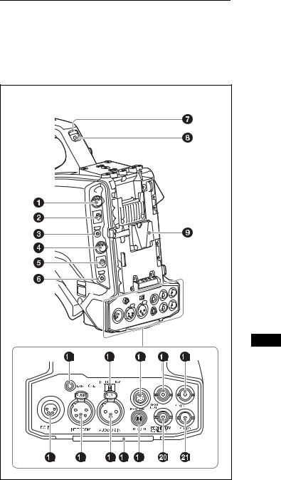
Rear
For the pin assignment of each connector, see “Pin Assignment” (page 68).
For details about removing the rear cover, see “Removing the rear cover” (page 17).
(With rear cover removed) |
a PGM LEVEL (program level) knob/assignable button |
Adjust the intercom PGM audio level.
When connected with the HXCU-FB80, this adjusts the PGM audio level input from the camera control unit.
In standalone operation mode, this adjusts signal level input on the SDI I/O connector.
No function is assigned to the assignable button by factory default. You can have a conversation on the intercom line while the button is pressed by assigning the function that turns the intercom microphone ON using REAR ENC SW on the <SWITCH ASSIGN2> page in the OPERATION menu.
b RET2 (return video 2) selector switch
Select the return video signal (2, 3, 4) displayed when the button assigned with the return video 2 function is pressed.
c RET1 (return video 1) button
Displays the return video 1 signal in the viewfinder while this button is pressed.
d INTERCOM (intercom volume) knob
Adjust the intercom volume level.
When connected with the HXCU-FB80, the intercom volume level can also be adjusted using the INTERCOM LEVEL knob on the rear of the camera.
In standalone operation mode, you can assign a function to this knob using REAR VR on the <VR ASSIGN> page in the OPERATION menu.
e INTERCOM MIC (intercom microphone) switch
The switch function varies depending on the PANEL TYPE setting on the <INTERCOM> page in the OPERATION menu (factory default: CE).
When the PANEL TYPE setting is CE
Functions as the intercom microphone line selector switch. PROD: Output the microphone on the PROD line.
OFF: Turn the microphone OFF.
ENG: Output the microphone on the ENG line.
When the PANEL TYPE setting is UCJ
Functions as the intercom line and microphone ON/OFF selector switch.
PROD: Select the PROD line and turn the microphone OFF. OFF: Select the ENG line and turn the microphone OFF.
ENG: Select the ENG line and turn the microphone ON (output on ENG line).
You can have a conversation on the selected line while the assignable button on the rear is pressed by assigning the function that turns the intercom microphone ON to the button.
Note
The intercom and microphone of the camera can be used when connected to a CA-TX70.
The intercom is connected to the line selected using the INTERCOM switch of the CA-TX70. ENG/PROD cannot be selected on the camera.
f CALL button
When you press this button, the red tally indicators on the connected camera control unit and external control device (for example, RCP or RM) will light up.
g TALLY indicators (red/green)
When the TALLY switch is set to ON, the tally indicator lights up when a tally signal is input to the connected camera control unit or a call signal is generated by pressing the CALL button.
h TALLY switch
Set to ON to activate the TALLY indicator function.
i Camera adaptor attachment
Attach an optional CA-TX70 HD Camera Adaptor and AC-DN10 AC Adaptor.
j EARPHONE jack (stereo, minijack)
Monitor the audio output from the intercom or audio signals input to the AUDIO 1 IN and AUDIO 2 IN connectors.
Set the earphone output on the <EARPHONE> page in the OPERATION menu.
The earphone volume level can be adjusted using the INTERCOM LEVEL knob.
k Audio input 2 selector switch
Select the audio level input to the AUDIO 2 IN connector.
13
+48V: To supply +48 V phantom power to condenser microphones MIC: When a microphone-level input is connected
LINE: When a line-level (0 dBu) signal source is connected
l REMOTE (remote control) connector (8-pin)
Connect a remote control unit for remote control the camera. When used in conjunction with the HXCU-FB80, connect with the REMOTE connector (8-pin) of the sub camera in order to send the Sub command.
Note
Before connecting/disconnecting a remote control unit, power off the camera first.
m TEST OUT connector (BNC type)
Outputs an analog signal.
You can select the VBS signal, Y signal of the VF connector, HD-SYNC, or SD-SYNC for output in the MAINTENANCE menu.
Note
VBS signal output is not available when HDR is set.
n SDI OUT connector (BNC type)
Outputs a 3G-SDI signal, HD-SDI, or SD-SDI signal.
You can select the output signal in the MAINTENANCE menu.
oDC IN (DC power supply input) connector (XLR 4-pin, female)
To operate the camera from an external DC power supply, connect an optional DC power cord to this connector and then connect the cord to an AC-DN10 AC Adaptor or other source.
p INTERCOM connector (XLR 5-pin)
Connect an XLR 5-pin headset for input and output of intercom audio signals.
q AUDIO 2 IN (audio input 2) connector (XLR type, 3-pin, female)
Connect to audio equipment or a microphone.
When the camera is connected to an HXCU-FB80, the input signal will be output from the AUDIO OUTPUT CH-2 connector. You can configure the camera so that the audio is embedded in the output from the SDI output (MIC2) on the <SDI OUT> page in the MAINTENANCE menu.
r Tail guard
Protects the cables connected to the connectors on the rear panel.
sDC OUT (DC power supply output) connector (4-pin, female)
Supplies power to a script light or other device (maximum 1.5 A).
tPROMPTER/GENLOCK (prompter signal output/external sync signal input) connector (BNC type)
When connected with a CCU, this connector outputs a VBS prompter signal.
In standalone operation mode, connect an external sync signal (BB or tri-level sync) for synchronizing the camera. If a VBS signal is input, you can check the input image in the viewfinder by pressing the RET button on the camera.
u SDI I/O connector (BNC type)
The input (IN) and output (OUT) mode can be changed using the menu.
In standalone operation mode, this displays the HD-SDI signal input on the SDI I/O connector in the viewfinder when the RET button is pressed.
You can select the input signal to be displayed in the viewfinder on the <EXT RETURN> page in the MAINTENANCE menu.
When connected to a CCU, the connector can be used as an HD PROMPTER output signal connector when set as an output (OUT). It can be used as an HD TRUNK input signal connector when set as an input (IN).
Note
Only HD-SDI signals in the same format specified on the <OUTPUT FORMAT> page in the MAINTENANCE menu can be input on the SDI I/O connector.
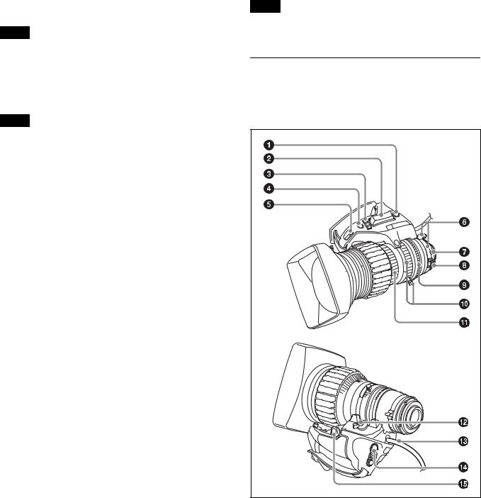
Lens (supplied with the HXC-FB80K/ HXC-FB80S)
For details about attaching a lens, see “Attaching and Adjusting the Lens” (page 23).
a RET (return video) button |
Displays the return video signal in the viewfinder while this button is pressed.
b Zoom see-saw switch
This is enabled when the zoom servo/manual selector knob is in the SERVO position. The zoom speed increases when you push the switch deeper, and decreases when you push less deeply.
14
W (Wide): Wide angle.
T (Telephoto): Telephoto.
c Iris operation mode selector switch
A (Auto): The iris is adjusted automatically. M (Manual): Adjust the iris with the iris ring.
d Iris one-push auto switch
When the iris operation mode selector switch is in the M position for manual adjustment, press this switch for instantaneous auto iris adjustment. The iris is automatically adjusted while the switch is pressed.
e Iris gain adjustment trimmer
Adjust the iris gain when the iris operation mode selector switch is in the A (Auto) position.
Flip off the rubber cap, and turn the iris gain adjustment trimmer using a screwdriver or similar object. Rotate clockwise to increase the gain, and rotate counterclockwise to decrease the gain.
f F.B. lock screw/F.B. adjustment ring
Use to adjust the flange back (flange focal length).
g Positioning pin
When attaching a lens, align this pin with the slot in the top center of the lens mount on the camera.
h Macro button/macro ring
Press and hold the macro button and rotate the macro ring to focus (close-up: 10 mm minimum).
i Iris ring
For manual iris adjustment, set the iris operation mode selector switch to the M (manual) position, then rotate this ring.
Note
Always set the iris operation mode selector switch to the M (manual) position before rotating the ring.
j Zoom lever/zoom ring
For manual zoom adjustment, set the zoom servo/manual selector switch to the MANU (manual) position, then operate this lever/ring.
k Focus ring
Rotate this ring to adjust the focus.
l Zoom servo/manual selector knob
SERVO: Power (servo) zoom. Control the zoom using the zoom see-saw switch.
MANU (Manual): Manual zoom. Control the zoom using the zoom lever/zoom ring.
m Lens cable
Connect to the LENS connector on the camera.
n VTR button
You can assign a function to this button using LENS VTR S/S on the <SWITCH ASSIGN2> page in the OPERATION menu.
o Zoom remote control connector
Connecting an optional zoom servo controller allows remote control of zooming.
Viewfinder
This section describes the HDVF-L10 viewfinder supplied with the HXC-FB80K.
For details about attaching the HDVF-L10 viewfinder, see “Attaching and Adjusting the Viewfinder” (page 18).
For details about the viewfinder supplied with the HXC-FB80S, refer to the operation manual for the HDVF-L750.
a Connector
Connect to the VF connector on the camera.
b Slide stopper
Prevents the viewfinder from coming off the camera when it is slid from side to side.
c Eyecup
d Diopter adjustment ring
Rotate the ring to adjust the image for clear focus.
e Eyepiece
You can raise the eyepiece or remove it when required by the usage situation.
f Viewfinder barrel
You can raise the viewfinder barrel or remove it when required by the usage situation.
g Tally indicator
The indicator lights up when a red tally signal is input to the camera. When an abnormality occurs, the tally indicator flashes to indicate a warning.
15
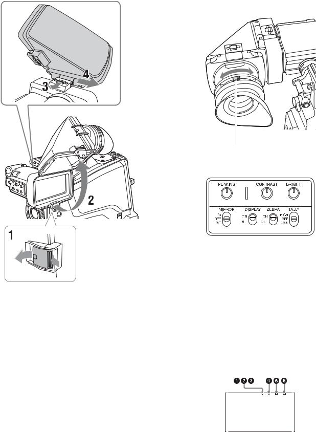
h PEAKING knob
Rotate clockwise to adjust the picture sharpness to make lens focusing easier. This has no effect on the output signal of the camera.
i CONTRAST knob
Adjust the contrast of the screen. This has no effect on the output signal of the camera.
j BRIGHT knob
Adjust the brightness of the screen. This has no effect on the output signal of the camera.
k TALLY switch
Used to control the tally indicator on the viewfinder. HIGH: The tally indicator brightness is set to high. OFF: The tally indicator is disabled.
LOW: The tally indicator brightness is set to low.
l ZEBRA (zebra pattern) switch
Use to control the zebra pattern display. ON: Display the zebra pattern.
OFF: Do not display the zebra pattern.
m DISPLAY switch
Use to control the display of text information. ON: Display text information.
OFF: Do not display text information.
Also used when switching to full-screen display mode or reduced display mode.
Note
There may be a mismatch between the DISPLAY switch ON/OFF state and the actual ON/OFF operation, depending on the camera settings.
n MIRROR switch
Used to reverse the image display on the monitor screen horizontally or vertically when the viewfinder barrel is raised up or rotated. L/R (left/right): Reverse the image horizontally.
OFF: Do not reverse the image.
B/T (bottom/top): Reverse the image vertically.
o Viewfinder cable
p Microphone holder
Connection and Setup
Connecting to a Camera Control Unit
When operating the camera in a system with a camera control unit (CCU), connect the CCU connector of the camera and the CAMERA connector of the CCU using an optoelectric composite cable.
When required, secure the cable, using the supplied cable clamp belt.
If connecting an HXCU-TX70 HD Camera Control Unit, refer to the operating instructions for the HXCU-TX70.
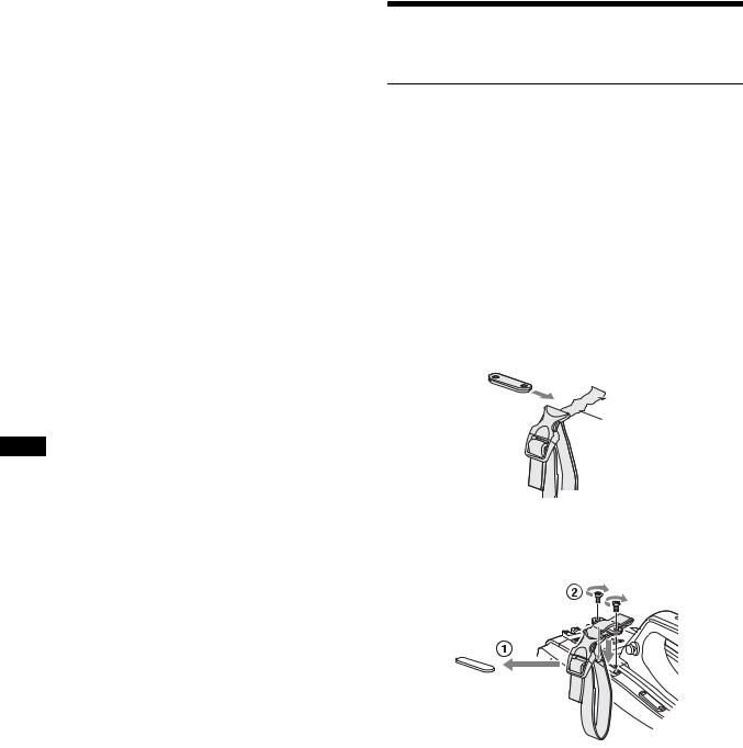
Attaching the cable clamp belt
1 Insert the belt bracket C into hole A or B of the cable clamp belt.
C
 B
B
A
2 1 Remove the screw-hole cover on the top rear of the camera and 2 secure the cable clamp belt to the camera using the two supplied screws (+B3×10).
16
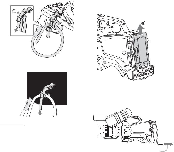
3 1 Release the buckle, 2 bundle the cable with the belt, 3 then close the buckle again.
If attaching the AC adaptor
Remove the rear cover and attach the AC adaptor to the camera.
Removing the rear cover
1 Hold the release button on the camera in, and 2 pull the rear cover up.
4 Adjust the length by pulling down on the end of the belt.
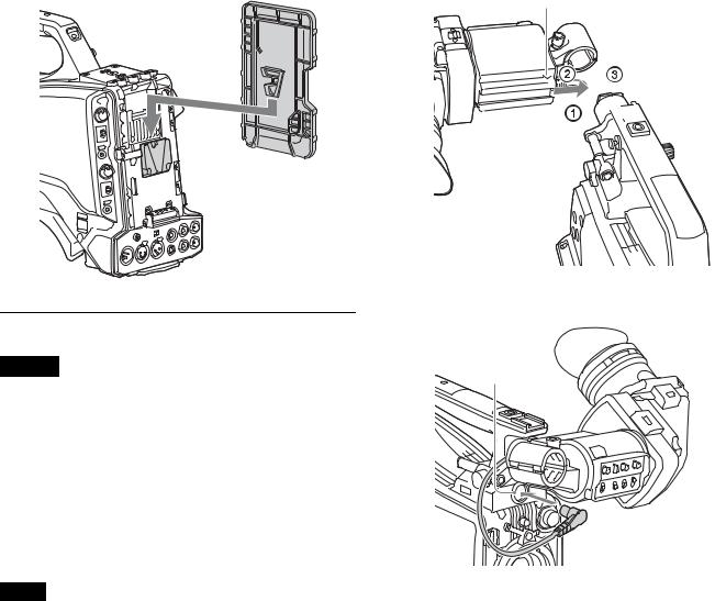
Attaching the AC adaptor
Attach an optional AC-DN10 AC adaptor to the camera, then connect to the AC power supply.
The AC-DN10 can supply up to 100 W of power.
AC Power Supply (Standalone
Operation)
Prepare an AC power supply when using the camera in standalone |
|
operation mode (without a CCU). |
|
For safety, use only the Sony AC adaptor listed below. |
To AC outlet |
• AC adaptor: AC-DN10 |
If using the DC IN connector
Connect the AC-DN10 AC adaptor to the DC IN output connector on the camera using an optional DC power cord.
17
To attach the rear cover
Align the guide on the inner side of the rear cover with the camera adaptor mount, and insert the cover.
Rear cover
1 1 Loosen the viewfinder left-to-right positioning ring, 2 attach the viewfinder to the viewfinder shoe, and 3 tighten the viewfinder left-to-right positioning ring.
Slide stopper
 2 3 1
2 3 1

Attaching and Adjusting the Viewfinder
Warning
When the viewfinder is attached, do not leave the camera with the eyepiece facing the sun.
Direct sunlight can enter through the eyepiece, be focused in the camera and cause a fire.
This section describes how to attach and adjust the HDVF-L10 viewfinder supplied with the HXC-FB80K. For details about attaching and adjusting the viewfinder supplied with the HXCFB80S, refer to the operation manual for the HDVF-L750.
Attaching the viewfinder
Attach the HDVF-L10 viewfinder supplied with the HXC-FB80K.
Notes
•Be sure to power off the camera before plugging the viewfinder connector into the VF connector of the camera. If the connector is plugged in while the power is on, the viewfinder may not operate correctly.
•Plug the viewfinder connector all the way into the VF connector of the camera. If the connector is not firmly connected, the image may become distorted or the tally indicator may not operate properly.
2 Connect the viewfinder connector to the VF connector.
VF connector
To detach the viewfinder
Detach in the reverse procedure of attaching. When detaching the viewfinder from the shoe, lift up the slide stopper on the viewfinder.
18

Adjusting the position
To adjust the viewfinder left-to-right position, loosen the left-to- right positioning ring. To adjust the front-to-back position, loosen the front-to-back positioning lever and lock knob.
Viewfinder left-to-right positioning ring
Viewfinder front-to-back positioning lever and lock knob
Adjusting the angle
You can adjust the angle of the viewfinder.
To reverse the display (image/text indication) vertically
The viewfinder can be rotated as much as 180 degrees so that it is facing the subject.
In this case, the image and other information displayed appear upside down on the screen.
To restore the normal display, set the MIRROR switch on the viewfinder to the B/T position to flip the display vertically.
Raising the viewfinder barrel or eyepiece
You can view the LCD screen inside the viewfinder or its mirrored image by raising the viewfinder barrel or eyepiece.
This section describes how to raise and detach the viewfinder barrel. The eyepiece can also be raised and detached in the same way.
To raise the viewfinder barrel
1 Push the clip on the bottom to release it, and 2 flip up the viewfinder barrel.
It locks at the 120-degree position.
LCD screen
Keep in the lock position for normal use.
You can also open it farther from the lock position. To set to the 120degree position again, return it to the closed position and then open it again.
19
To detach the viewfinder barrel |
Adjusting the diopter |
|
Rotate the diopter adjustment ring until the viewfinder image is |
|
sharpest. |
Diopter adjustment ring
Adjusting the screen
1 Push the clip on the bottom to release it.
2 Flip up the viewfinder barrel.
3 Slide the button on the top in the direction opposite to the viewfinder barrel to unlock the barrel.
4 Detach the viewfinder barrel by sliding it horizontally.
To reverse the display (image/text indication) horizontally
Set the MIRROR switch on the viewfinder to the L/R position to reverse the picture and other information displayed in the viewfinder horizontally.
You can adjust the following items.
Peaking: Adjust using the PEAKING knob.
Contrast: Adjust using the CONTRAST knob.
Brightness: Adjust using the BRIGHT knob.
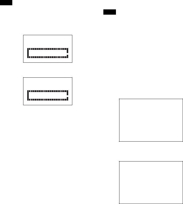
Screen display mode and indicator
The viewfinder screen can be set to full-screen display mode or reduced display mode.
To switch the display mode, switch the DISPLAY switch “ON t OFF t ON t OFF” or “OFF t ON t OFF t ON” in quick succession.
Full-screen display mode
Displays the image so that it fills the full-screen display area. Tally and other indicators are superimposed on the camera image. Use this mode when the resolution of the displayed image is more important.
20
Reduced display mode
Displays the camera image at a reduced size, with the tally and other indicators displayed in the spaces above and below the camera image.
Use this mode when the clear visibility of the tally and other indicators is more important.
Indicators are located at the top and bottom of the screen to indicate the status of the camera and viewfinder.
a G TALLY (green tally) indicator (green)
Lights up when a green tally signal is input.
b R TALLY (red tally) indicator (red)
Lights up when a red tally signal is input.
c Y TALLY (yellow tally) indicator (yellow)
Not supported by the camera.
Note
In full-screen display mode, the display position of the tally indicators is fixed in one location. Accordingly, only one R/G/Y tally indicator can be lit at any one time, regardless of the signal that is input. The display priority of the tally indicator is red, green, and yellow, in that order.
d [!] indicator (amber)
Using the ‘!’ IND function, the ‘!’ indicator appears when nonstandard settings are in effect.
e BATT (battery) indicator (red)
Lights up or flashes to indicate the status of the power supply to the camera.
Lit: Significant voltage decrease Flashing: Voltage decrease
f SAVE indicator (amber)
Not supported by the camera.
Attaching the V-Wedge Shoe
Attachment
To attach the HDVF-L750 Viewfinder supplied with the HXCFB80S or an optional HDVF-L770/HDVF-EL75, connect the V- wedge shoe attachment supplied with the camera or viewfinder to the camera and then attach the viewfinder to the attachment.
The procedure for attaching the attachment is given below.
For details about attaching a viewfinder, refer to the operation manual for the viewfinder.
1 Remove the four plastic caps from the camera.
 Plastic caps
2 Attach the V-wedge show attachment (supplied) to the camera using the hex wrench (supplied) and four hex socket bolts (4×12, supplied).
3 Insert the viewfinder firmly into the V-wedge shoe attachment.
A click sound occurs when properly attached.
Front-to-back position adjustment (when HDVF-L770 or HDVF-EL75 is attached)
To attach an HDVF-L770 LCD Color Viewfinder or HDVF-EL75 HD Electronic Viewfinder, move the mount wedge on the bottom of the viewfinder 15 mm toward the camera operator from the default position.
For details about attaching, refer to the operation manual for the viewfinder.
Using the Camera for the First Time
The camera is shipped with the area of use setting in an unset state. To use the camera, you need to first set the area of use.
21
Once the area setting is complete, set the current date and time.
Note
The camera cannot be used if the area of use is not set.
Setting the area of use
1 Turn on the camera.
The screen for setting the area of use appears in the viewfinder.
F O R M A T S E T T I N G
 C O U N T R Y :
 N O T S E L E C T E D
S Y S T E M L I N E : 1 0 8 0
S Y S T E M S C A N : I n t e r l a c e
S E T F O R M A T
A N D T U R N O F F O N C E . 
2 Press the menu control knob.
The area of use becomes selectable.
F O R M A T S E T T I N G
 C O U N T R Y : ? N O T S E L E C T E D
S Y S T E M L I N E : 1 0 8 0
S Y S T E M S C A N : I n t e r l a c e
S E T F O R M A T
A N D T U R N O F F O N C E . 
3 Rotate the menu control knob to select the area of use.
Setting |
Area of use |
Output composite |
System |
|
|
signal |
frequency |
NTSC(J) |
NTSC area |
NTSC signal |
59.94i |
AREA |
(Japan) |
without setup |
|
|
|
|
|
NTSC AREA |
NTSC area (for |
NTSC signal with |
59.94i |
|
areas other than |
setup (7.5IRE) |
|
|
Japan) |
|
|
|
|
|
|
PAL AREA |
PAL area |
PAL signal |
50i |
|
|
|
|
4 Change the SYSTEM LINE (video resolution) and SYSTEM SCAN (video scanning mode) settings according to the video format you are using.
SYSTEM LINE
Setting |
Resolution (Horizontal × Vertical) |
1080 |
1080 lines (1920×1080) |
|
|
720 |
720 lines (1280×720) |
|
|
SYSTEM SCAN
Setting |
Video scanning mode |
Interlace |
Interlaced |
|
|
Progressive |
Progressive |
|
|
PsF |
Progressive |
|
|
Supported formats: 1080/59.94i, 1080/59.94P, 1080/50i, 1080/50P, 1080/29.97PsF, 1080/25PsF, 1080/23.98PsF, 720/59.94P, 720/50P
5 Turn the camera off and then back on.
The camera is now ready for use.
To change the area of use
Change the setting using COUNTRY on the <OUTPUT FORMAT> page in the MAINTENANCE menu.
Note
The setting is switched to the CCU setting when a CCU is connected.
Setting the date/time
Set the built-in clock to the current local time on the <DATE> page in the MAINTENANCE menu.
For details about menu operations, see “Menu Operation” (page 34).
1 Turn on the camera.
2 Press and hold the menu control knob and set the DISPLAY/MENU switch to MENU.
The camera enters menu mode, and “TOP” is displayed at the upper-right corner of the screen.
3 Rotate the menu control knob to align the , pointer with
TOP and press the menu control knob.
The TOP MENU screen is displayed.
<TOP MENU>
cUSER
USER MENU CUSTOMIZE ALL
 OPERATION
 PAINT
PAINT
 MAINTENANCE
 FILE
FILE  DIAGNOSIS
4 Rotate the menu control knob to align the , pointer with
MAINTENANCE and press the menu control knob.
The CONTENTS page of the MAINTENANCE menu appears.
CONTENTS |
M00 TOP |
|
xx |
|
|
c01.<AUTO |
SETUP> |
|
02.<WHITE |
SHADING> |
|
03.<BLACK |
SHADING> |
|
04.<AUTO |
IRIS> |
|
05.<LENS> |
|
|
06.<CIS COMP> |
|
|
07.<AUDIO> |
|
|
08.<CALL/TALLY> |
|
|
09.<OUTPUT FORMAT> |
|
|
10.<TEST |
OUT> |
|
11.<SDI OUT> 12.<TRUNK> 13.<GENLOCK> 14.<DATE>
5 Rotate the menu control knob to scroll the page and align the , pointer with <DATE> and press the menu control knob.
The <DATE> page appears.
Press the menu control knob to confirm the page selection.
22
 Loading...