


 Loading...
Servo Screen 390
Service Manual
E382 E394E 061 01 02 02
Important |
Servo Screen 390 |
|
|
Important
General
The documentation for the Servo Screen 390 consists of:
•Operating Manual
•Service Manual
•Spare Parts List
The Operating Manual is an indispensable complement to the Service Manual for proper servicing.
As the Servo Screen 390 is a part of the Servo Ventilator system, there are also other documents that can be useful when servicing the Servo Screen 390:
•Servo Ventilator 300/300A
–Operating Manual
–Service Manual
–Circuit Diagram
–Reference Manual, Computer Interface
•Servo Ventilator 900C/E
–Operating Manual
–Service Manual
–Circuit Diagram
–Reference Manual, SCM 990
Text inside a box is used to highlight important information.
In addition to the Important information given here and in the related documents (e. g. in the Operating Manual), always pay attention to applicable local and national regulations.
Responsibility for the safe functioning of the equipment reverts to the owner or user in all cases in which service or repair has been done by a non-professional or by persons who are not employed by or authorized by Siemens, and when the equipment is used for other than its intended purpose.
There are two different versions of the Servo Screen 390:
•Serial No. 10000 or lower – Equipped with Computer board PC 1662 and a software memory card of PC Card™-type.
•Serial No. 10001 or higher – Equipped with Computer board PC 1835 and a software memory card of CompactFlash™-type.
All information in this Service Manual is valid for both versions unless stated otherwise.
Hazard notices
Make sure that all cables are disconnected from the connection ports when disassembling or assembling the Servo Screen 390.
Service
When working with ESD sensitive components, always use a grounded wrist band and grounded work surface. Adequate service tools must also be used.
Worn-out batteries must be returned |
|
|
to the place of purchase or to a place |
|
|
where they can be safely disposed |
|
|
of. Batteries must not be disposed |
|
|
of with ordinary waste. All other |
|
|
parts shall be discarded according to |
|
|
hospital rules and in an environ- |
Pb |
|
mentally safe way. |
||
|
Functional check
After any service intervention in the Servo Screen 390, perform a Functional check according to the instructions in the Operating Manual.
To responsible service personnel
The contents of this document are not binding. If any significant difference is found between the product and this document, please contact Siemens for further information.
We reserve the right to modify products without amending this document or advising the user.
Only personnel authorized by Siemens shall be permitted to service or repair the Servo Screen 390. Only Siemens-Elema genuine spare parts must be used. PC boards (spare parts) must always be kept in a package for sensitive electronic devices. Siemens will not otherwise assume responsibility for the materials used, the work performed, or any possible consequences of same.
2 |
Siemens-Elema AB |
E382 E394E 061 01 02 02 |

Servo Screen 390 |
Contents |
|
|
Contents |
|
1. Introduction ....................................................................... |
5 1 |
2. Description of functions ................................................... |
11 2 |
3. Disassembly and assembly.............................................. |
17 3 |
4. Service procedures ........................................................... |
25 4 |
5. Troubleshooting ................................................................ |
37 5 |
6. Index .................................................................................. |
41 6 |
7. Diagrams............................................................................ |
45 7 |
E382 E394E 061 01 02 02 |
Siemens-Elema AB |
3 |

Notes |
Servo Screen 390 |
|
|
Notes
4 |
Siemens-Elema AB |
E382 E394E 061 01 02 02 |

Servo Screen 390 |
1. Introduction |
|
|
1. Introduction
....................................................General |
6 |
1 |
Hardware overview ................................. |
7 |
|
.....................................Main sections |
8 |
|
Display section ................................... |
8 |
|
Computer section ............................... |
9 |
|
Firmware/software overview................... |
9 |
|
Firmware ............................................ |
9 |
|
Software............................................. |
9 |
|
E382 E394E 061 01 02 02 |
Siemens-Elema AB |
5 |

1. Introduction
1
SS-000X
SS-001X
Servo Screen 390
General
Servo Screen 390 is a computer unit that reads information from a ventilator, makes calculations, and presents the information to the operator in a clear, logically organized manner.
The primary purpose of Servo Screen 390 is to provide a central location for the display of all parameter information from the ventilator. It provides information on system and patient conditions, logically assembled in a way that presumes presentations including curves.
Servo Screen 390 does not control the ventilator or any other medical equipment.
Servo Screen 390 is compatible with the following ventilator systems:
•Servo Ventilator 300/300A
•Servo Ventilator 900C/E systems that use Servo Computer Module 990 (SCM 990)
More information about the compatible ventilators can be found in the chapter “Technical specifications” in the Operating Manual.
6 |
Siemens-Elema AB |
E382 E394E 061 01 02 02 |
Servo Screen 390 |
1. Introduction |
|
|
SS-002X
4
-003X |
5 |
|
SS |
||
|
 3
3
 1
1
 2
2
6 |
7 |
8 |
9 |
10 |
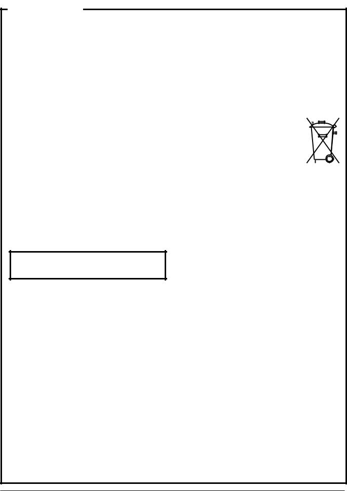
Hardware overview
Servo Screen 390 unit is a small, compact, ergonomically-designed computer unit. It is 1 manufactured from materials suitable for
use in a clinical environment and is designed specifically for integration with existing ventilator equipment.
The primary features of the Servo Screen 390 are:
•An electro-luminescent, mono-chromatic screen (1) which provides displays that are clearly visible within the bedside working area.
•A power on/off switch (2).
•A single operator control including a pulse generator in the form of an easy-to-use knob (3), which can be only turned or pressed.
•A removable software memory card under the protective cover (4) for easy software updates. More information about software upgrading can be found in the chapter 4, “Service procedures”.
•Connection ports as follows:
–KBD port (5) for connection of a keyboard. For service use only.
–PRINTER port (6) for connection of a printer.
–COM port (7) for serial communication with other equipment. For future applications. Dependent on the software version.
–VENT port (8) for serial communication with the ventilator.
–CRT port (9) for connection of an external monitor.
–PWR port (10) for connection to a power source.
More information about the connection ports can be found in the chapter 7, “Diagrams”.
E382 E394E 061 01 02 02 |
Siemens-Elema AB |
7 |
1. Introduction
1
2
Servo Screen 390
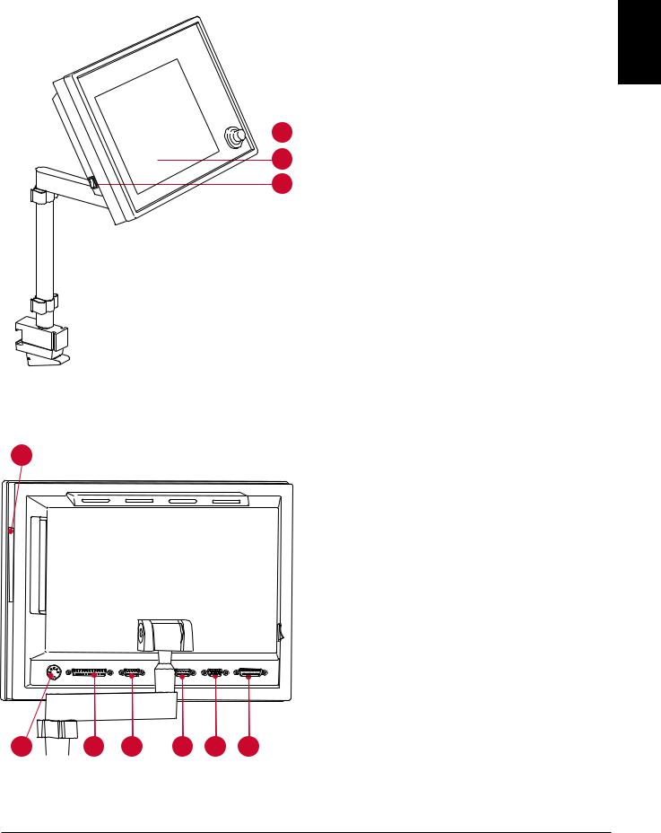
Main sections
Servo Screen 390 can be separated into two main sections:
•Display section (1)
•Computer section (2)
The support arm (3) is always used to mount the Servo Screen 390 on a ventilator cart or wall rail.
 1
1
3
SS-032X
Display section
SS-033X
The anti-reflex coated front panel filter (4) protects the display (5) and makes it easy to keep the display clean.
To reduce EMC radiation to the environment, a cover plate (6) is mounted at the rear of the display.
4 |
5 |
6 |
8 |
Siemens-Elema AB |
E382 E394E 061 01 02 02 |

Servo Screen 390
7
-034X |
8 |
|
SS |
||
|
1. Introduction
|
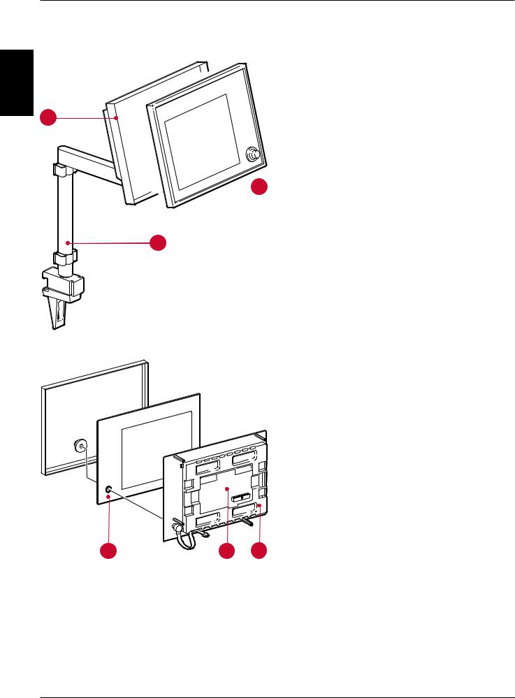
Computer section |
|
|
The two PC boards mounted in the computer |
|
|
section are: |
1 |
|
• Computer board (7), containing micro- |
|
|
|
|
|
processor, SS390-BIOS, internal memory |
|
|
and an interface for the software memory |
|
|
card. All connection ports except the power |
|
|
port are mounted on the computer board. |
|
|
There are two different versions of the |
|
|
Computer board (7), PC 1662 and PC 1835. |
|
|
• Adapter board PC 1663 (8), containing |
|
|
voltage distribution and display interface. |
|
|
A fan (9) inside the computer unit provides |
|
|
forced air cooling for the PC boards. The fan |
|
9 |
has a rubber suspension to reduce noise. |
|
Firmware/software overview
Firmware
The SS390-BIOS on the computer board initializes the system and starts the application software.
The SS390-BIOS can be upgraded if required.
Software
The operating system and the Servo Screen application software is supplied on a removable software memory card. The user interface provided by this software is described in the Operating Manual.
The software memory card is very easy to replace in case of future software upgrades.
E382 E394E 061 01 02 02 |
Siemens-Elema AB |
9 |

1. Introduction |
Servo Screen 390 |
|
|
Notes
1
10 |
Siemens-Elema AB |
E382 E394E 061 01 02 02 |
Servo Screen 390 |
2. Description of functions |
|
|
2. Description of functions
General .................................................... |
12 |
|
Power supply........................................... |
12 |
|
With Servo Ventilator 300/300A ......... |
12 |
|
|
||
With Servo Ventilator 900C/E ............. |
12 |
2 |
Adapter board.......................................... |
13 |
|
General ............................................... |
13 |
|
.............................Voltage distribution |
13 |
|
Signal adaption ................................... |
13 |
|
Brightness control .............................. |
13 |
|
Fan control.......................................... |
13 |
|
Board identity ..................................... |
13 |
|
Internal power cable ........................... |
13 |
|
ON/OFF switch .................................. |
14 |
|
Display connection cable .................... |
14 |
|
Fan ..................................................... |
14 |
|
Computer board ...................................... |
14 |
|
General ............................................... |
14 |
|
Software memory card ....................... |
15 |
|
Battery................................................ |
15 |
|
Pulse generator .................................. |
16 |
|
Connection ports ................................ |
16 |
|
Display..................................................... |
16 |
|
E382 E394E 061 01 02 02 |
Siemens-Elema AB |
11 |

2. Description of functions |
Servo Screen 390 |
|
|
General
The text in this chapter refers to the block diagram in chapter 7, “Diagrams” (on the inside of the back cover).
2
Power supply
With Servo Ventilator 300/300A
The power supply is connected to the power inlet port PWR (P21) on Servo Screen 390. The internal power cable connects the power inlet port to the ADAPTER BOARD at P18. The PWR port is described in chapter
7, “Diagrams”.
Power to the Servo Screen 390 is supplied from the Servo Ventilator 300/300A auxiliary equipment output N78.
Connector N78 is described (output signals and limitations) in the Servo Ventilator 300/ 300A – Service Manual.
With Servo Ventilator 900C/E
The power supply is connected to the power inlet port PWR (P21) on Servo Screen 390. The internal power cable connects the power inlet port to the ADAPTER BOARD at P18. The PWR port is described in chapter
7, “Diagrams”.
Power to the Servo Screen 390 is supplied from an AC Power Adapter 124 when used with a Servo Ventilator 900C/E.
Technical specifications for the AC Power Adapter 124:
Mains power supply ........... |
100 – 240 V |
Mains frequency................. |
50 – 60 Hz |
ON/OFF-indication .............. |
Green LED indi- |
|
cates power on |
Output voltage range .......... |
24 V DC ±10% |
Output power ..................... |
max. 50 W |
Earth leakage current, |
|
normal condition |
|
(IEC 601-1-1) ....................... |
30 A |
Fuse (internal) ..................... |
2.4 A slow |
12 |
Siemens-Elema AB |
E382 E394E 061 01 02 02 |

Servo Screen 390 |
2. Description of functions |
|
|
Adapter board
General
The functional blocks on the ADAPTER BOARD PC 1663 are:
• VOLTAGE DISTRIBUTION
Signal adaption
The control signals from the COMPUTER BOARD PC 1662/PC 1835 to the display are adapted in this block and furthered to the main block DISPLAY via P20.
•SIGNAL ADAPTION
•BRIGHTNESS CONTROL
•FAN CONTROL
•BOARD IDENTITY
Further functional blocks connected to the
ADAPTER BOARD are:
•INTERNAL POWER CABLE
•ON/OFF SWITCH
•DISPLAY CONNECTION CABLES
Brightness control
The brightness in the display can be selected 2 using the SYSTEM MENU in the application software. The selected brightness is then controlled via this block and furthered to the main block DISPLAY via P19.
When exchanging PC 1663, a setting of the brightness level may be required, refer to chapter "3. Disassembly and assembly", section "Assembling the computer section".
• FAN
The ADAPTER BOARD is connected directly to the COMPUTER BOARD via N5.
Voltage distribution
The inlet power is fused at F1 (3.15 A fast). Replacing the fuse is described in chapter 4, “Service procedures”.
The different voltage levels used in the Servo Screen 390 are regulated by and distributed from this block.
The distributed voltage levels are:
1.+12 V (±5%), max. 2.6 A. An overvoltage protection cuts the voltage distribution at typ. 14.6 V.
2.+5 V (±3%), max. 3.0 A. An overvoltage protection cuts the voltage distribution at typ. 6.2 V.
Fan control
An NTC-resistor on PC 1663 senses the air temperature inside the Servo Screen 390.
If the air temperature inside the unit exceeds approx. 53°C (127°F), the fan is switched on. When the temperature drops below approx. 45°C (113°F), the fan is switched off.
Board identity
PC 1663 is equipped with a BOARD IDENTITY function that makes it possible for the COMPUTER BOARD PC 1662/PC 1835 to recognize the PC 1663 version. This function is intended for possible future versions, e.g. new types of displays.
Internal power cable
The internal power cable connects the PC 1663 (P18) with the power inlet port PWR (P21).
E382 E394E 061 01 02 02 |
Siemens-Elema AB |
13 |

2. Description of functions |
Servo Screen 390 |
|
|
ON/OFF switch
The ON/OFF SWITCH turns the power supply to the Servo Screen 390 on or off. This is the only device for turning the unit on or off. No other action is needed, e. g. when shutting down the Servo Screen 390.
2 |
Display connection cables |
The two DISPLAY CONNECTION CABLES connect |
|
|
the ADAPTER BOARD to the DISPLAY. |
|
One flat cable connects SIGNAL ADAPTION |
|
signals from P20 on PC 1662/PC 1835 to |
|
display connector J1. |
|
One cable connects BRIGHTNESS CONTROL |
|
signals from P19 on PC 1662/PC 1835 to |
|
display connectors J2 and J3. |
Fan
The Servo Screen 390 is equipped with a FAN. The fan is controlled by the block FAN
CONTROL.
The purpose of this fan is to provide forced air cooling inside the unit. The air stream enters through the ventilation holes in the lower part of the unit and exits through the ventilation holes in the upper part of the unit.
Computer board
General
There are two different versions of the
COMPUTER BOARD:
•PC 1662. Factory mounted on Servo Screen 390 with Serial No. 10000 or lower. Software memory card of PC Card™-type is used.
•PC 1835. Factory mounted on Servo Screen 390 with Serial No. 10001 or higher. Software memory card of CompactFlash™- type is used.
The two PC boards are interchangable. Refer to further information in the Spare Parts List when replacing a PC 1662 with a PC 1835.
The functional blocks on the COMPUTER BOARD PC 1662/PC 1835 are:
•MICROPROCESSOR
–80486SX, 25 MHz on PC 1662
–Pentium, 166 MHz on PC 1835.
•VGA CONTROLLER
•BUS INTERFACE including:
–Diskette drive interface (not used)
–Hard disk interface (for test purposes only)
–Two serial ports
–One parallel port
–Keyboard controller
•PULSE GENERATOR INTERFACE
•VOLTAGE & FUNCTION MONITORING
•INTERNAL MEMORY. The size of the internal memory is optimized for the software version. The internal memory is mounted on a standard socket and can be replaced if required by future software upgrades.
•VIDEO MEMORY
14 |
Siemens-Elema AB |
E382 E394E 061 01 02 02 |

Servo Screen 390 |
2. Description of functions |
|
|
•SRAM (only on PC 1662). This battery backed up memory contains software settings (e.g. battery replacement date),
TRENDS and the EVENT LIST.
Note – On PC 1835, TRENDS and EVENT LIST are stored on the CompactFlash™ card and thus not dependent on the battery.
•SOFTWARE MEMORY CARD INTERFACE
•SS390-BIOS. Contains low-level software (BIOS, drivers, start-up screen including software loading messages and initial program load of the application software). There are two different versions of the SS390-BIOS:
–SS390-PROM mounted on PC 1662. This PROM is mounted on a PROM socket and can be upgraded (replaced) if required.
–SS390-FLASH mounted on PC 1835. This FLASH memory can be upgraded (new software downloaded) if required.
Refer to chapter 4, “Service procedures” for furher information regarding upgrades.
The computer is equipped with procedures for self-testing and the self-test result can be displayed in the SERVICE MENU. See chapter 4, “Service procedures”.
Further functional blocks connected to the
COMPUTER BOARD are:
• SOFTWARE MEMORY CARD
Software memory card
The SOFTWARE MEMORY CARD contains the operating system and the Servo Screen 390 application software. Loading of the software into the INTERNAL MEMORY is initialized by the SS390-BIOS during start-up.
There are two different versions of the
SOFTWARE MEMORY CARD:
• PC Card™ used on PC 1662. |
2 |
•CompactFlash™-card used on PC 1835. Note – As patient related TRENDS and unit related EVENT LIST are stored on the CompactFlash-card, it is not recommended to move a CompactFlash-card between different units.
The software on the memory card is specifically designed for Servo Screen 390, and cannot be used on a standard PC.
The software memory card is easy to replace in case of future software upgrades. See chapter 4, “Service procedures”.
Battery
The lithium BATTERY (3.6 V) is used to back up the computer setup stored in the CMOSRAM and, for PC 1662, also to back up the SRAM. If the battery is disconnected, factory default settings will be used next time the Servo Screen 390 is started.
•BATTERY
•PULSE GENERATOR
•CONNECTION PORTS
The COMPUTER BOARD is connected directly to the ADAPTER BOARD via P5.
The battery must be replaced every three years. The message ”Replace Servo Screen 390 battery” in the message window indicates when the battery should be replaced. A new three-year period will start when the battery replacement has been confirmed with the BATTERY CHANGE icon in
the SERVICE MENU.
Replacing the battery and Battery change confirmation is described in chapter
4, “Service procedures”.
E382 E394E 061 01 02 02 |
Siemens-Elema AB |
15 |
Loading...