


 Loading...
XR-40X/XR-41X/XG-F260X
SERVICE MANUAL
No. S57J1XR-40X//
MULTIMEDIA PROJECTOR
XR-40X
XR-41X
MODELS XG-F260X
In the interests of user-safety (Required by safety regulations in some countries) the set should be restored to its original condition and only parts identical to those specified should be used.
OUTLINE
This Service Manual covers the differences from XR-30X/XG-F210X. For other technical information, refer to the XR- 30S/XR-30X/XG-F210X (No. S47E3XR-30XS/) Service Manual.
|
|
|
|
|
|
|
|
CONTENTS |
|
OUTLINE AND MODIFIED PARTS LIST |
Parts Guide |
|||
|
OUTLINE............................................................ |
i |
||
|
MODIFIED PARTS............................................. |
i |
||
SAFETY PRECAUTION |
|
|
||
|
IMPORTANT SERVICE SAFETY |
|
|
|
|
NOTES.............................................................. |
ii |
||
|
Precautions for using lead-free solder ............ |
vii |
||
CHAPTER 1. OPERATION MANUAL |
|
|
||
[1] |
Specifications ................................................ |
1-1 |
|
|
CHAPTER 2. ELECTRICAL ADJUSTMENT |
|
|
||
[1] |
ELECTRICAL ADJUSTMENT....................... |
2-1 |
|
|
[2] Adjustment mode process menu................... |
2-4 |
|
||
Parts marked with "  " are important for maintaining the safety of the set. Be sure to replace these parts with specified ones for maintaining the safety and performance of the set.
This document has been published to be used for after sales service only.
The contents are subject to change without notice.
XR-40X/XR-41X/XG-F260X
OUTLINE AND MODIFIED PARTS LIST
OUTLINE
This Service Manual covers the differences from XR-30X/XG-F210X. For other technical information, refer to the XR-30S/XR-30X/XG-F210X (No. S47E3XR-30XS/) Service Manual.
MODIFIED PARTS
(XR-30X/XG-F210X → XR-40X/XR-41X/XG-F260X)
Ref.No. |
Description |
XR-30X/XG-F210X |
XR-40X/XR-41X/XG-F260X |
Note |
PRINTED WIRING BOARD ASSEMBLIES |
|
|
|
|
|
BALLAST POWER Ass'y |
DSETUE149FMG0 |
← |
- |
|
BALLAST CONTROL Unit |
DUNTKE150WEF0 |
← |
- |
|
PHOTO SENSOR Unit |
DUNTKE151WEF0 |
← |
- |
|
R/C RECEIVER Unit |
DUNTKE152WEF0 |
← |
- |
|
MAIN Unit |
DUNTKE153FMF0 (XR-30X) |
DUNTKE153FMF2 (XR-40X/41X) |
No parts changed |
|
MAIN Unit |
DUNTKE153FMF4 (XG-F210X) |
DUNTKE153FMF3 (XG-F260X) |
No parts changed |
|
DMD Unit |
DUNTKE154WEF0 |
← |
- |
|
|
|
|
|
CABINET AND MECHANICAL PARTS : Please refer to a Parts Guide.
OPTICAL MECHANISM PARTS : Please refer to a Parts Guide.
SUPPLIED ACCESSORIES : Please refer to a Parts Guide.
PACKING PARTS AND ACCESSORIES : Please refer to a Parts Guide.
SERVICE JIGS AND EQUIPMENT(USE FOR SERVICING) : Please refer to a Parts Guide.
i
XR-40X/XR-41X/XG-F260X
SAFETY PRECAUTION
IMPORTANT SERVICE SAFETY NOTES
IMPORTANT SERVICE SAFETY NOTES (for USA)
 Service work should be performed only by qualified service technicians who are thoroughly familiar with all safety checks and servicing guidelines as follows:
WARNING
1.For continued safety, no modification of any circuit should be attempted.
2.Disconnect AC power before servicing.
BEFORE RETURNING THE PROJECTOR:
(Fire & Shock Hazard)
Before returning the projector to the user, perform the following safety checks:
1.Inspect lead wires are not pinched between the chassis and other metal parts of the projector.
2.Inspect all protective devices such as non-metallic control knobs, insulating materials, cabinet backs, adjustment and compartment covers or shields, isolation resistor-capacity networks, mechanical insulators, etc.
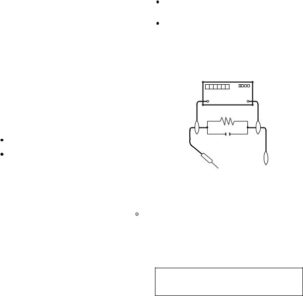
3.To be sure that no shock hazard exists, check for current leakage in the following manner:
Plug the AC cord directly into a 120 - volt AC outlet, (Do not use an isolation transformer for this test). Using two clip leads, connect a 1.5k ohm, 10 watt resistor paralleled by a 0.15µF capacitor in parallel between all exposed metal cabinet parts and earth ground.
Use an AC voltmeter with sensitivity of 5000 ohm per volt., or higher, sensitivity to measure the AC voltage drop across the resistor.
All checks must be repeated with the AC plug connection reversed. (If necessary, a non-polarized adapter plug must be used only for the purpose of completing these checks.)
Any reading of 0.4 volts RMS (this corresponds to 0.27 milliamp. AC.) or more is excessive and indicates a potential shock hazard which must be corrected before returning the unit to the owner.
|
DVM |
|
AC SCALE |
|
1.5k ohm |
|
10W |
|
0.15 µF |
|
TEST PROBE |
TO EXPOSED |
CONNECT TO |
METAL PARTS |
KNOWN EARTH |
|
GROUND |
/////////////////////////////////////////////////////////////////////////////////////////////////////////////////////////////////////////////////
SAFETY NOTICE
Many electrical and mechanical parts in DLPR Projector have special safety-related characteristics. These characteristics are often not evident from visual inspection, nor can protection afforded by them be necessarily increased by using replacement components rated for higher voltage, wattage, etc.
Replacement parts which have these special safety characteristics are identified in this manual; electrical components having such features are identified by “ ” and shaded areas in the Replacement Parts Lists and Schematic Diagrams. For continued protection,
replacement parts must be identical to those used in the original circuit. The use of a substitute replacement parts which do not have the same safety characteristics as the factory recommended replacement parts shown in this service manual, may create shock, fire or other hazards.
WARNING: The bimetallic component has the primary conductive side exposed. Be very careful in handling this component when the power is on.
/////////////////////////////////////////////////////////////////////////////////////////////////////////////////////////////////////////////////
ii
XR-40X/XR-41X/XG-F260X
PRECAUTIONS A PRENDRE LORS DE LA REPARATION
 Ne peut effectuer la réparation qu' un technicien spécialisé qui s'est parfaitement accoutumé à toute vérification de sécurité et aux conseils suivants.
AVERTISSEMENT
1.N'entreprendre aucune modification de tout circuit. C'est dangereux.
2.Débrancher le récepteur avant toute réparation.
VERIFICATIONS CONTRE L'INCEN-DIE ET LE CHOC ELECTRIQUE
Avant de rendre le récepteur à l'utilisateur, effectuer les vérifications suivantes.
1.Inspecter tous les faisceaux de câbles pour s'assurer que les fils ne soient pas pincés ou qu'un outil ne soit pas placé entre le châssis et les autres pièces métalliques du récepteur.
2.Inspecter tous les dispositifs de protection comme les boutons de commande non-métalliques, les isolants, le dos du coffret, les couvercles ou blindages de réglage et de compartiment, les réseaux de résistance-capacité, les isolateurs mécaniques, etc.
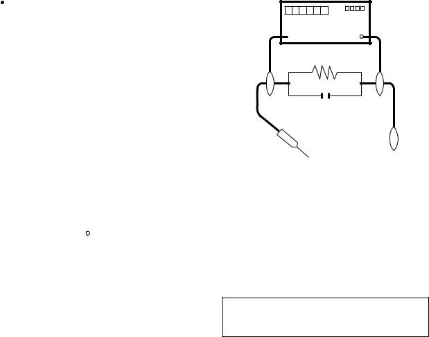
3.S'assurer qu'il n'y ait pas de danger d'électrocution en vérifiant la fuite de courant, de la facon suivante:
Brancher le cordon d'alimentation directem-ent à une prise de courant de 120 - V. (Ne pas utiliser de transformateur d'isolation pour cet essai).
 A l'aide de deux fils à pinces, brancher une résistance de 1.5 kΩ 10 watts en parallèle avec un condensateur de 0.15µF en série avec toutes les pièces métalliques exposées du coffret et une terre connue comme une conduite électrique ou une prise de terre branchée à la terre.
 Utiliser un voltmètre CA d'une sensibilité d'au moins 5000Ω/V pour mesurer la chute de tension en travers de la résistance.
 Toucher avec la sonde d'essai les pièces métalliques exposées qui présentent une voie de retour au châssis (antenne, coffret métallique, tête des vis, arbres de commande et des boutons, écusson, etc.) et mesurer la chute de tension CA en-travers de la résistance. Toutes les vérifications doivent être refaites après avoir inversé la fiche du cordon d'alimentation. (Si nécessaire, une prise d'adpatation non polarisée peut être utilisée dans le but de terminer ces vérifications.)
La tension de pointe mesurèe ne doit pas dépasser 0.4V (correspondante au courant CA de pointe de 0.27mA). Dans le cas contraire, il y a une possibilité de choc électrique qui doit être supprimée avant de rendre le récepteur au client.
DVM
 ECHELLE CA
1.5k ohm
10W
0.15µF
SONDE D'ESSAI
AUX PIECES |
BRANCHER A UNE |
|
METALLIQUES |
||
TERRE CONNUE |
||
EXPOSEES |
||
|
/////////////////////////////////////////////////////////////////////////////////////////////////////////////////////////////////////////////////////
AVIS POUR LA SECURITE
De nombreuses pièces, électriques et mécaniques, dans les projecteur à DLP R présentent des caractéristiques spéciales relatives à la sécurité, qui ne sont souvent pas évidentes à vue.
Le degré de protection ne peut pas être nécessairement augmentée en utilisant des pièces de remplacement étalonnées pour haute tension, puissance, etc.
Les pièces de remplacement qui présentent ces caractéristiques sont identifiées dans ce manuel; les pièces électriques qui présentent ces particularités sont identifiées par la marque “ ” et hachurées dans la
liste des pièces de remplacement et les diagrammes schématiques. Pour assurer la protection, ces pièces doivent être identiques à celles utilisées dans le circuit d’origine. L’utilisation de pièces qui n’ont pas les mêmes caractéristiques que les pièces recommandées par l’usine, indiquées dans ce manuel, peut provoquer des électrocutions, incendies ou autres accidents.
AVERTISSEMENT: La composante bimétallique dispose du conducteur primaire dénudé. Faire attention lors de la manipulation de cette composante sous tension.
/////////////////////////////////////////////////////////////////////////////////////////////////////////////////////////////////////////////////////
iii
NOTE TO SERVICE PERSONNEL
//////////////////////////////////////////////////////////////
UV-RADIATION PRECAUTION
//////////////////////////////////////////////////////////////
The light source, lamp, in the projector emits small amounts of UV-Radiation.
AVOID DIRECT EYE AND SKIN EXPOSURE.
To ensure safety please adhere to the following:
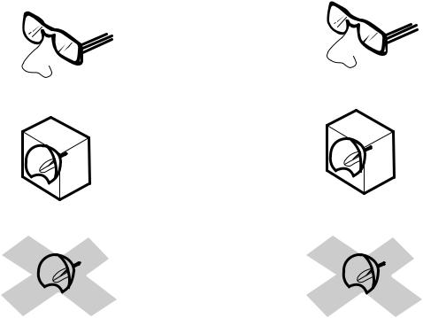
1.Be sure to wear sun-glasses when servicing the projector with the lamp
turned “on” and the top
enclosure removed.
2. Do not operate the lamp outside of the lamp housing.
3.Do not operate for more than 2 hours with the enclosure removed.
XR-40X/XR-41X/XG-F260X
NOTE POUR LE PERSONNEL D’ENTRETIEN
//////////////////////////////////////////////////////////////
PRECAUTION POUR LES RADIATIONS UV
//////////////////////////////////////////////////////////////
La source de lumière, la lampe, dans le projecteur émet de petites quantités de radiation UV.
EVITEZ TOUTE EXPOSITION DIRECTE DES YEUX ET DE LA PEAU.
Pour votre sécurité, nous vous prions de respecter les points suivants:
1. Toujours porter des lunettes de soleil lors d’un entretien du projecteur
avec la lampe allumée et le haut du coffret retiré.
2.Ne pas faire fonctionner la lampe à l’extérieur du boîtier de lampe.
3.Ne pas faire fonctionner plus de 2 heures avec le coffret retiré.
UV-Radiation and Medium Pressure
Lamp Precautions
1.Be sure to disconnect the AC plug when replacing the lamp.
2.Allow one hour for the unit to cool down before servicing.
3.Replace only with same type lamp. Type AN-XR30LP rated 200W DC.
4.The lamp emits small amounts of UV-Radiation, avoid direct-eye contact.
5.The medium pressure lamp involves a risk of explosion. Be sure to follow installation instructions described below and handle the lamp with care.
Précautions pour les radiations UV et la lampe moyenne pression
1.Toujours débrancher la fiche AC lors du remplacement de la lampe.
2.Laisser l’unité refroidir pendant une heure avant de procéder à l’entretien.
3.Ne remplacer qu’avec une lampe du même type. Type AN-XR30LP, caractéristique 200W-DC.
4.La lampe émet de petites quantités de radiation UVéviter tout contact direct avec les yeux.
5.La lampe moyenne pression implique un risque d’explosion. Toujours suivre les instructions d’installation décrites ci-dessous et manipuler la lampe avec soin.
iv
XR-40X/XR-41X/XG-F260X
////////////////////////////////////////////////////////////////
UV-RADIATION PRECAUTION (Continued)
////////////////////////////////////////////////////////////////

 Lamp Replacement
Note:
Since the lamp reaches a very high temperature during units operation replacement of the lamp should be done at least one hour after the power has been turned off. (to allow the lamp to cool off.)
Installing the new lamp, make sure not to touch the lamp (bulb) replace the lamp by holding its reflector
2 .
[Use original replacement only.]
1 Lamp
2 Reflector
////////////////////////////////////////////////////////////////
PRECAUTION POUR LES RADIATIONS UV (Suite)
////////////////////////////////////////////////////////////////

 Remplacement de la lampe
Remarque:
Comme la lampe devient très chaude pendant le fonctionnement de l’unité, son remplacement ne doit être effectué au moins une heure après avoir coupé l’alimentation (pour permettre à la lampe de refroidir). En installant la nouvelle lampe, s’assurer de ne pas toucher la lampe (ampoule). Remplacer la lampe en tenant son réflecteur 2 .
[N’utiliser qu’un remplacement d’origine.]
1 Lampe
2 Reflecteur
DANGER ! –– Never turn the power on without the lamp to avoid electric-shock or damage of the devices since the stabilizer generates high voltages at its start.
Since small amounts of UV-radiation are emitted from an opening between the exhaust fans, it is recommended to place the cap of the optional lens on the opening during servicing to avoid eye and skin exposure.
DANGER ! –– Ne jamais mettre sous tension sans la lampe pour éviter un choc électrique ou des dommages des appareils car le stabilisateur génère de hautes tensions à sa mise en route.
Comme de petites quantités de radiation UV sont émises par une ouverture entre les ventilateurs aspirants, il est recommandé de placer le capuchon de l’optique optionnelle sur l’ouverture pendant l’entretien pour éviter une exposition des yeux et la peau.
v

XR-40X/XR-41X/XG-F260X
WARNING: High brightness light source, do not stare into the beam of light, or view directly. Be especially careful that children do not stare directly into the beam of light.
WARNING: TO REDUCE THE RISK OF FIRE OR ELECTRIC SHOCK, DO NOT EXPOSE THIS UNIT TO MOISTURE OR WET LOCATIONS.
|
CAUTION |
The lighting flash with arrowhead within a |
|
|
RISK OF ELECTRIC SHOCK. |
triangle is intended to tell the user that |
|
|
parts inside the product are risk of electric |
||
|
DO NOT REMOVE SCREWS |
||
|
EXCEPT SPECIFIED USER |
shock to persons. |
|
|
SERVICE SCREW. |
|
|
CAUTION: TO REDUCE THE RISK OF ELECTRIC SHOCK, |
The exclamation point within a triangle is |
||
|
DO NOT REMOVE CABINET. |
||
|
intended to tell the user that important |
||
NO USER-SERVICEABLE PARTS EXCEPT LAMP UNIT. |
|||
operating and servicing instructions are in |
|||
|
REFER SERVICING TO QUALIFIED SERVICE |
||
|
PERSONNEL. |
the manual with the projector. |
|
CAUTION |
|
||
(POWER Unit) |
|
||
|
For continued |
|
|
|
protection against a |
|
|
|
risk of fire, replace |
|
|
|
only with same type |
|
|
6.3A 250V |
6.3A, AC250V fuse. |
|
|
(F701) |
|
||
AVERTISSEMENT: Source lumineuse de grande intensité. Ne pas fixer le faisceau lumineux ou le regarder directement. Veiller particulièrement à éviter que les enfants ne fixent directement le faisceau lumineux.
AVERTISSEMENT: AFIN D’EVITER TOUT RISQUE D’INCENDIE OU D’ELECTROCUTION, NE PAS PLACER CET APPAREIL DANS UN ENDROIT HUMIDE OU MOUILLE.
ATTENTION |
RISQUE |
D’ÉLECTROCUTION. NE |
PASR ETIRER LES VIS Á |
L’EXCEPTION DE LA VIS DE |
REPARATION UTILISATEUR |
SPECIFIEES |
ATTENTION: POUR EVITER TOUT RISQUE |
D’ELECTROCUTION, NE PAS RETIRER LE CAPOT. |
AUCUNE DES PIECES INTERIEURES N’EST REPARABLE |
PAR L’UTILISATEUR, A L’EXCEPTION DE L’UNITE DE |
LAMPE. POUR TOUTE REPARATION, S’ADRESSER A UN |
TECHNICIEN D’ENTRETIEN QUALIFIE. |
L’éclair terminé d’une flèche à l’intérieur d’un triangle indique à l’utilisateur que les pi‘eces se trouvant dans l’appareil sont susceptibles de provoquer une décharge électrique.
Le point d’exclamation à l’intérieur d’un triangle indique à l’utilisateur que les instructions de fonctionnement et d’entretien sont détaillées dans les documents fournis avec le projecteur.
PRECAUTION
(Unité de PUTSSANCE)
Pour une protection continue contre un risques d’incendie, ne remplacer qu’avec un fusible 6.3A,AC250V
6.3A 250V du même type.
(F701)
vi
XR-40X/XR-41X/XG-F260X
Precautions for using lead-free solder
Employing lead-free solder
•"PWBs" of this model employs lead-free solder. The LF symbol indicates lead-free solder, and is attached on the PWBs and service manuals. The alphabetical character following LF shows the type of lead-free solder.
Example:
L F a
Indicates lead-free solder of tin, silver and copper.
Using lead-free wire solder
•When fixing the PWB soldered with the lead-free solder, apply lead-free wire solder. Repairing with conventional lead wire solder may cause damage or accident due to cracks.
As the melting point of lead-free solder (Sn-Ag-Cu) is higher than the lead wire solder by 40 °C, we recommend you to use a dedicated soldering bit, if you are not familiar with how to obtain lead-free wire solder or soldering bit, contact our service station or service branch in your area.
Soldering
•As the melting point of lead-free solder (Sn-Ag-Cu) is about 220 °C which is higher than the conventional lead solder by 40 °C, and as it has poor solder wettability, you may be apt to keep the soldering bit in contact with the PWB for extended period of time. However, Since the land may be peeled off or the maximum heat-resistance temperature of parts may be exceeded, remove the bit from the PWB as soon as you confirm the steady soldering condition.
Lead-free solder contains more tin, and the end of the soldering bit may be easily corroded. Make sure to turn on and off the power of the bit as required.
If a different type of solder stays on the tip of the soldering bit, it is alloyed with lead-free solder. Clean the bit after every use of it. When the tip of the soldering bit is blackened during use, file it with steel wool or fine sandpaper.
•Be careful when replacing parts with polarity indication on the PWB silk.
Lead-free wire solder for servicing
Part No. |
|
Description |
Code |
|
|
|
|
ZHNDAi123250E |
J |
φ0.3mm 250g(1roll) |
BL |
ZHNDAi126500E |
J |
φ0.6mm 500g(1roll) |
BK |
ZHNDAi12801KE |
J |
φ1.0mm 1kg(1roll) |
BM |
vii
Loading...