


XV-Z1U
Table of contents
 Loading...
I
-xv-z1 u
SHARP SERVICE MANUAL
S88V9XV-Zl U//
PAL/SECAM/NTSC SYSTEM
LCD PROJECTOR
MODEL xv-z1 u
I
of user-safety (Required by safety regulations in some countries) the set should be re-
condition and only parts identical to those specified should be used.
/
CONTEN--
is
Page
. SPECIFICATIONS
...............................................
2
. INPORTANT SERVICE SAFETY NOTES ..........
3
. NOTE TO SERVICE PERSONNEL ....................
4
. OPERATION MANUAL
.......................................
7
. REMOVING OF MAJOR PARTS
......................
10
l CONTROLLING THE TOTAL
OPERATING HOURS OF THE LAMP .............. 15
l RESETTING THE LAMP
OPERATING HOUR COUNTER
...................... 16
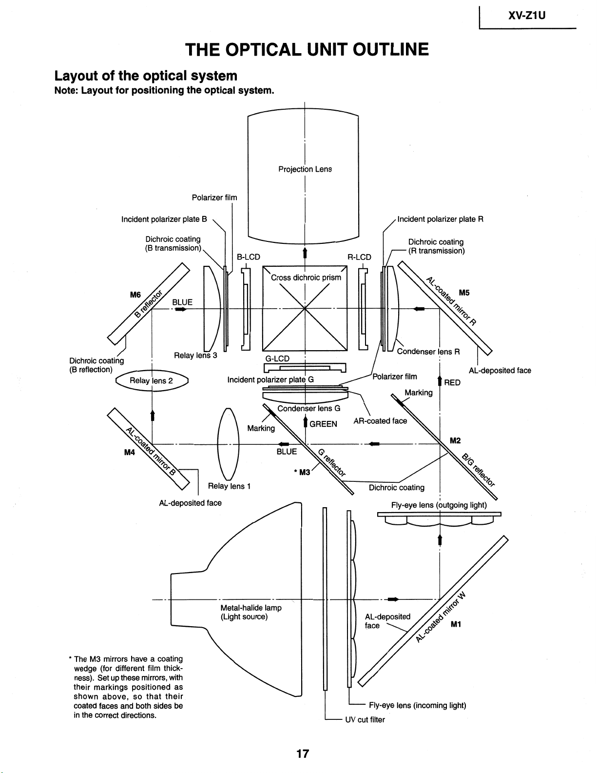
. THE OPTICAL UNIT OUTLINE
........................ 17
l CONVERGENCE AND
FOCUS ADJUSTMENT
....................................
18
. ELECTRICAL ADJUSTMENT
..........................
22
. TROUBLESHOOTING TABLE
..........................
30
CHASSIS LAYOUT . . . . . . . . . . . . . . . . . . . . . . . . . . . . . . . . . . . . . . . . . . . .
35
BLOCK DIAGRAM
. . . . . . . . . . . . . . . . . . . . . . . . . . . . . . . . . . . . . . . . . . . .
37
OVERALL WIRING
DIAGRAM . . . . . . . . . . . . . . . . . . . . . . . . .
39
DESCRIPTION OF SCHEMATIC DIAGRAM . . . . . 41
WAVEFORMS . . . . . . . . . . . . . . . . . . . . . . . . . . . . . . . . . . . . . . . . . . . . . . . . . . .
42
SCHEMATIC DIAGRAM
. . . . . . . . . . . . . . . . . . . . . . . . . . . . . . . . . . .
43
PRINTED WIRING BOARD ASSEMBLIES . . . . . . 79
PARTS LIST
1
Page
n ELECTRICAL PARTS . . . . . . . . . . . . . . . . . ..*.............
89
n CABINET AND MECHANICAL PARTS . . . . . 113
n ACCESSORIES PARTS
. . . . . . . . . . . . . . . . . . . . . . . . . . . 122
n PACKING PARTS . . . . . . . . . . . . . . . . . . . . . . . . . . . . . . . . . . . . . .
122
PACKING OF THE SET . . . . . . . . . . . . . . . . . . . . . ..*..........
123
SHARP CORPORATlON
This document has been published to be used for
after sales service only.
The contents are subject to change without notice.
xv=21 u
Specifications
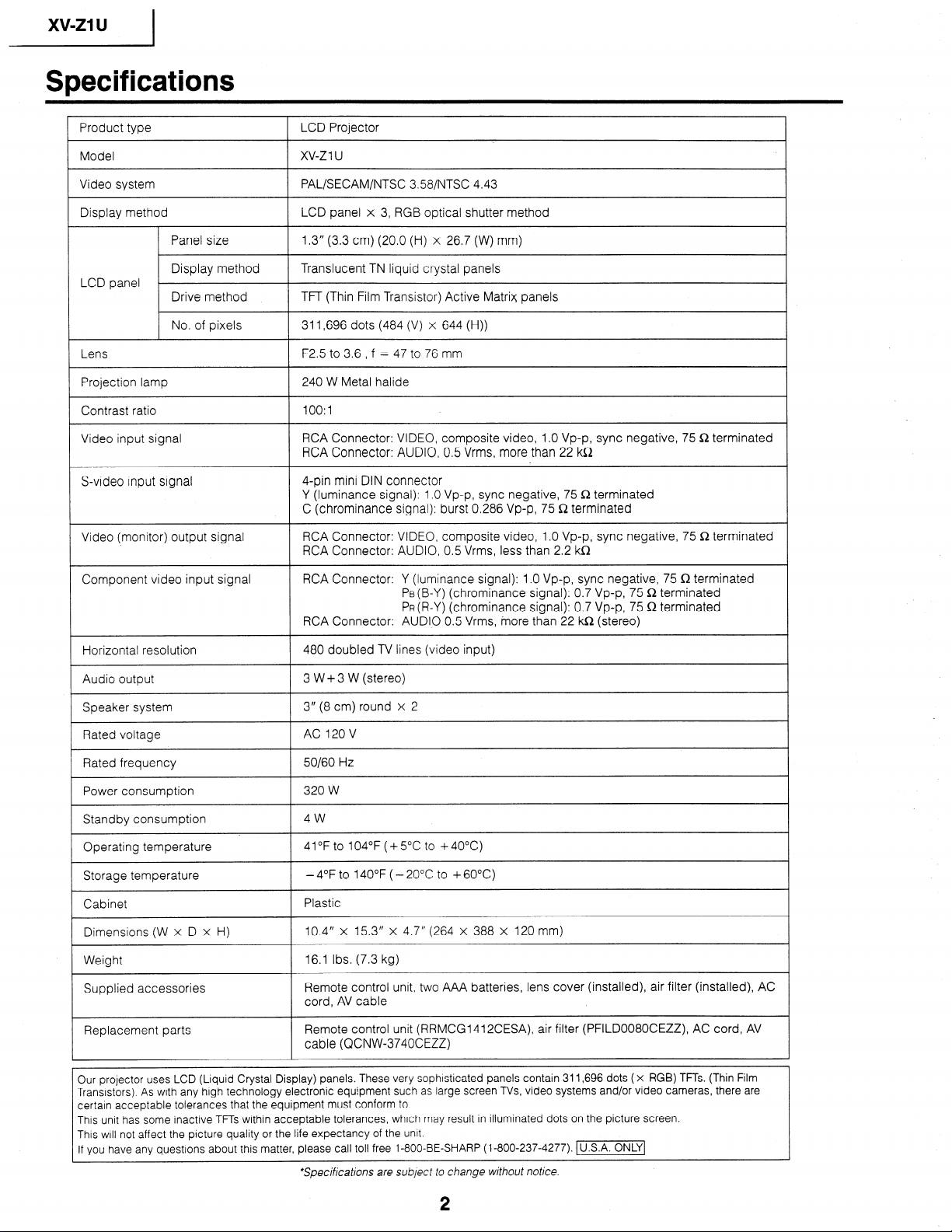
1 Product type 1 LCD Projector
Model xv-z 1 u
Video system PAL/SECAM/NTSC 358/NTSC 4.43
Display method LCD panel x 3, RGB optical shutter method
Panel size 1.3” (3.3 cm) (20.0 (H) x 26.7 (W) mm)
Display method Translucent TN liquid crystal panels
LCD panel
Drive method TFT (Thin Film Transistor) Active Matrix panels
No. of pixels 311,696 dots (484 (V) x 644 (H))
Lens
F2.5 to 3.6 , f = 47 to 76 mm
Projection lamp
240 W Metal halide
Contrast ratio
lOO:l
Video input signal
RCA Connector: VIDEO, composite video, 1 .O Vp-p, sync negative, 75 Q terminated
RCA Connector: AUDIO, 0.5 Vrms, more than 22 kQ
S-video input signal
4-pin mini DIN connector
Y (luminance signal): 1 .O Vp-p, sync negative, 75 Q terminated
C (chrominance signal): burst 0.286 Vp-p, 75 Q terminated
Video (monitor) output signal
RCA Connector: VIDEO, composite video, 1 .O Vp-p, sync negative, 75 Q terminated
RCA Connector: AUDIO, 0.5 Vrms, less than 2.2 kS2
Component video input signal
RCA Connector: Y (luminance signal): 1 .O Vp-p, sync negative, 75 Q terminated
PB(B-Y) (chrominance signal): 0.7 Vp-p, 75 R terminated
PR (R-Y) (chrominance signal): 0.7 Vp-p, 75 Q terminated
RCA Connector: AUDIO 0.5 Vrms, inore than 22 kR (stereo)
480 doubled TV lines (video input)
Audio output
3 W + 3 W (stereo)
Speaker system
3” (8 cm) round x 2
Rated voltage
AC 120 V
/ Rated frequency
50160 Hz
320 W
Standby consumption
4w
I_
Operating temperature
/ 41°F to 104°F (+5”C to +4O”C)
Storage temperature
- 4°F to 140°F ( - 20°C to + 60°C)
Plastic
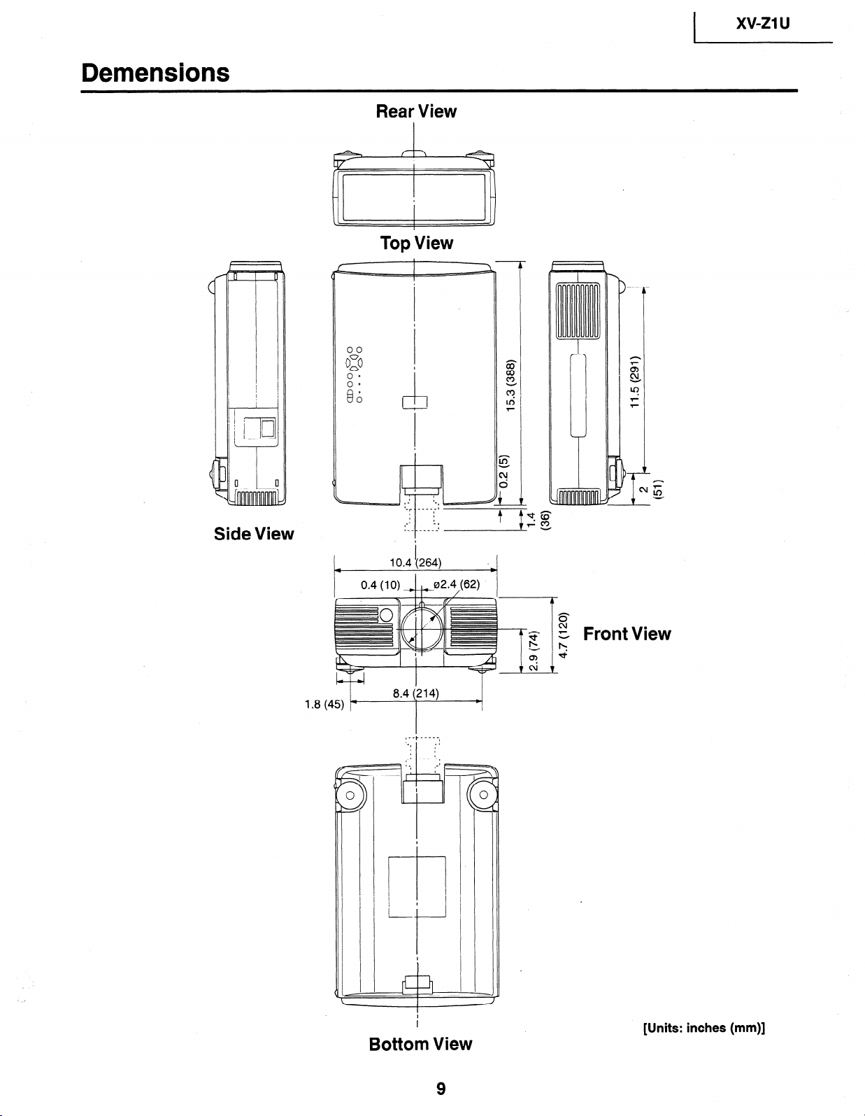
10.4” x 15.3” x 4.7” (264 x 388 x 120 mm)
Weight
16.1 Ibs. (7.3 kg)
Supplied accessories
Remote control unit, two AAA batteries, lens cover (installed), air filter (installed), AC
cord, AV cable
Replacement parts
Remote control unit (RRMCG1412CESA) air filter (PFILD0080CEZZ), AC cord, AV
cable (QCNW-3740CEZZ)
Our projector uses LCD (Liquid Crystal Display) panels. These very sophisticated panels contain 311,696 dots ( x RGB) TFTs. (Thin Film
Transistors). As with any high technology electronic equipment such as large screen TVs, video systems and/or video cameras, there are
certain acceptable tolerances that the equipment must conform to.
This unit has some inactive TFTs within acceptable tolerances, which may result in illuminated dots on the picture screen.
This will not affect the picture quality or the life expectancy of the unit.
If you have any questions about this matter, please call toll free 1-800-BE-SHARP (l-800-237-4277). (U.S.A.]
*Specifications are subject to change without notice.
2
) xv-ZlU
IMPORTANT SERVICE SAFETY NOTES
n Service work should be performed only by qualified service technicians who are thoroughly
familiar with all safety checks and servicing guidelines as follows:
WARNING
1. For continued safety, no modification of any circuit
should be attempted.
2. Disconnect AC power before servicing.
BEFORE RETURNING THE PROJECTOR:
(Fire & Shock Hazard)
Before returning the projector to the user, perform
the following safety checks:
1 .
2 .
3
.
Inspect lead wires are not pinched between the
chassis and other metal parts of the projector.
Inspect all protective devices such as non-metallic
control knobs, insulating materials, cabinet backs,
adjustment and compartment covers or shields,
isolation resistor-capacity networks, mechanical
insulators, etc.
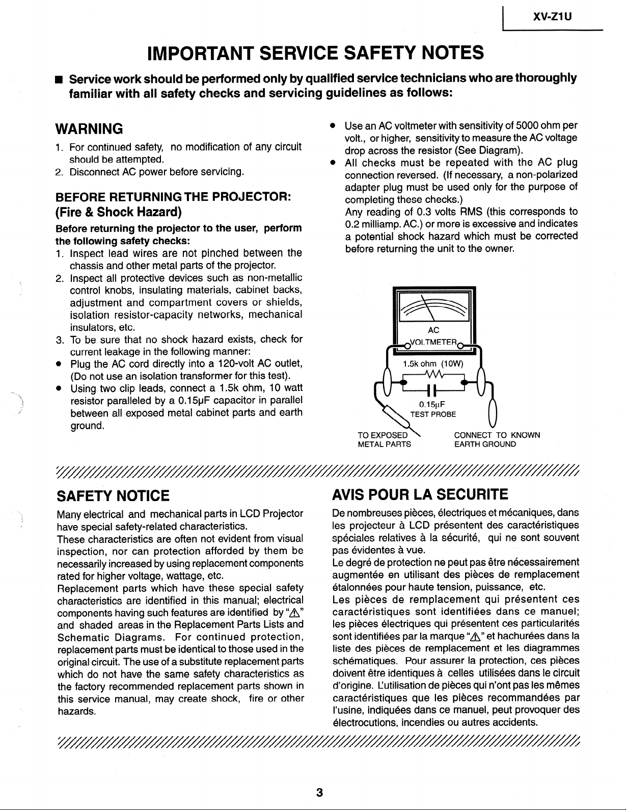
To be sure that no shock hazard exists, check for
current leakage in the following manner:
Plug the AC cord directly into a 120,volt AC outlet,
(Do not use an isolation transformer for this test).
Using two clip leads, connect a 1.5k ohm, 10 watt
resistor paralleled by a 0.15uF capacitor in parallel
between all exposed metal cabinet parts and earth
ground.
Use an AC voltmeter with sensitivity of 5000 ohm per
volt., or higher, sensitivity to measure the AC voltage
drop across the resistor (See Diagram).
All checks must be repeated with the AC plug
connection reversed. (If necessary, a non-polarized
adapter plug must be used only for the purpose of
completing these checks.)
Any reading of 0.3 volts RMS (this corresponds to
0.2 milliamp. AC.) or more is excessive and indicates
a potential shock hazard which must be corrected
before returning the unit to the owner.
TEST PROBE
TO EXPOSED
METAL PARTS
CONNECT TO KNOWN
EARTH GROUND
SAFETY NOTICE
Many electrical and mechanical parts in LCD Projector
have special safety-related characteristics.
These characteristics are often not evident from visual
inspection, nor can protection afforded by them be
necessarily increased by using replacement components
rated for higher voltage, wattage, etc.
Replacement parts which have these special safety
characteristics are identified in this manual; electrical
components having such features are identified by “A”
and shaded areas in the Replacement Parts Lists and
Schematic Diagrams.
For continued protection,
replacement parts must be identical to those used in the
original circuit. The use of a substitute replacement parts
which do not have the same safety characteristics as
the factory recommended replacement parts shown in
this service manual, may create shock, fire or other
hazards.
De nombreuses pieces, electriques et mecaniques, dans
AVIS POUR LA SECURITE
les projecteur a LCD presentent des caracteristiques
speciales relatives a la securite, qui ne sont souvent
pas evidentes a vue.
Le degre de protection ne peut pas etre necessairement
augmentee en utilisant des pieces de remplacement
etalonnees pour haute tension, puissance, etc.
Les pieces de remplacement qui presentent ces
caracteristiques sont identifiees dans ce manuel;
les pieces electriques qui presentent ces particularites
sont identifiees par la marque “A” et hachurees dans la
liste des pieces de remplacement et les diagrammes
schematiques. Pour assurer la protection, ces pieces
doivent etre identiques a celles utilisees dans le circuit
d’origine. Cutilisation de pieces qui n’ont pas les memes
caracteristiques que les pieces recommandees par
I’usine, indiquees dans ce manuel, peut provoquer des
electrocutions, incendies ou autres accidents.
NOTE TO SERVICE
PERSONNEL
////////////////////////////////////////
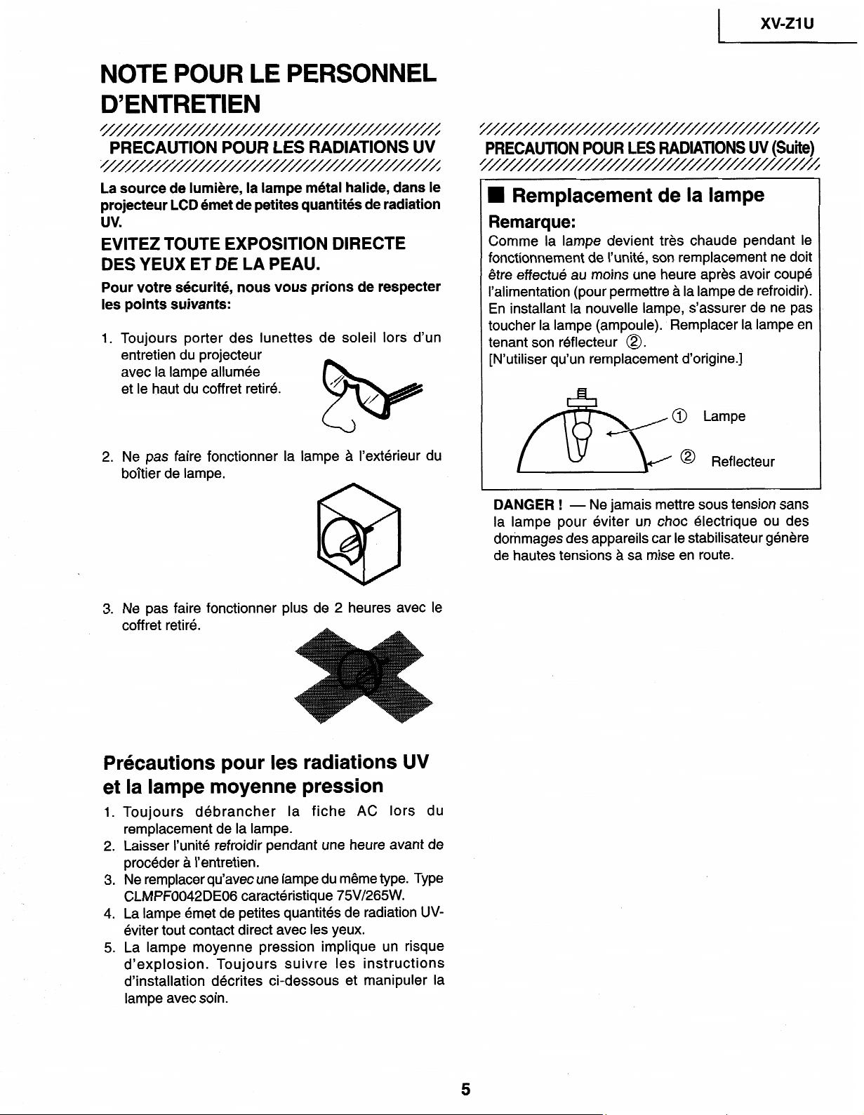
UV-RADIATION PRECAUTION
;///////////////////
The light source,
metal halide lamp, in the LCD
projector emits small amounts of UV-Radiation.
To ensure safety please adhere to the following:
1. Be sure to wear sun-glasses when servicing the
projector with the lamp
turned “on” and the top
enclosure removed.
/
&
/
2. Do not operate the lamp outside of the lamp housing.
3. Do not operate for more than 2 hours with the
enclosure removed.
UV-Radiation and Medium Pressure
Lamp Precautions
1 .
2
.
3
.
4 .
5
.
Be sure to disconnect the AC plug when replacing
the lamp.
Allow one hour for the unit to cool down before
servicing.
Replace only with same type lamp. Type
CLMPF0042DE06 rated 75V/265W.
The lamp emits small amounts of UV-Radiation, avoid
direct-eye contact.
The medium pressure lamp involves a risk of
explosion. Be sure to follow installation instructions
described below and handle the lamb with care.
UV-RADIATION PRECAUTION
/’
Continued)
I////////////
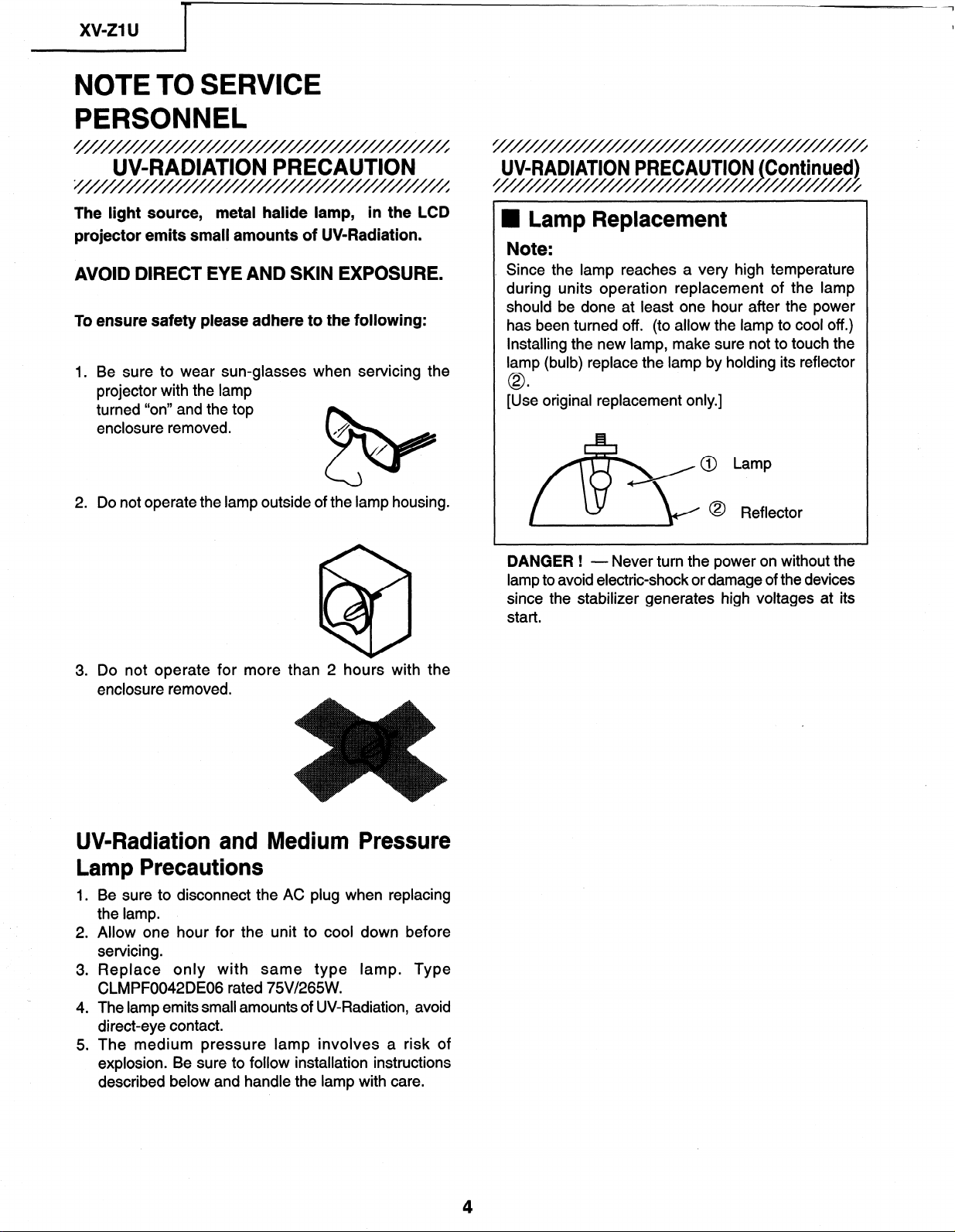
U Lamp Replacement
Note:
Since the lamp reaches a very high temperature
during units operation replacement of the lamp
should be done at least one hour after the power
has been turned off. (to allow the lamp to cool off.)
Installing the new lamp, make sure not to touch the
lamp (bulb) replace the lamp by holding its reflector
0
[Use original replacement only.]
@ Lamp
@ Reflector
DANGER !
- Never turn the power on without the
lamp to avoid electric-shock or damage of the devices
since the stabilizer generates high voltages at its
start.
4
I
xv-z1
u
D’ENTRETIEN
////////////////////////////////////////
PRECAUTION POUR LES RADIATIONS UV
;///////////////////
La
source de
lumi&e,
la
lampe
metal
halide, dans le
projecteur LCD 6met de
petites
quantitbs de
radiation
uv
EiTEZ TOUTE EXPOSITION DIRECTE
DES
YEUX ET DE LA PEAU.
Pour votre sbcurit6, nous vous prions de respecter
les points suivants:
1. Toujours porter des
lunettes de soleil lors d’un
entretien du projecteur
avec la
lampe allumee
L %
et le haut
du
coffret
retire.
2. Ne pas faire fonctionner la lampe a I’exterieur du
boltier de lampe.
3. Ne pas faire fonctionner plus de 2 heures avec le
coff ret retire.
Prkautions pour les radiations UV
et la lampe moyenne pression
1
.
2 .
3 *
4
.
5
.
Toujours debrancher la fiche AC lors du
remplacement de la lampe.
Laisser I’unite refroidir pendant une heure avant de
proceder a I’entretien.
Ne remplacer qu’avec une lampe du meme type. Type
CLMPF0042DE06 caracteristique 75V/265W.
La lampe emet de petites quantites de radiation UV-
eviter tout contact direct avec les yeux.
La lampe moyenne pression implique un risque
d’explosion. Toujours suivre les instructions
d’installation d&rites ci-dessous et manipuler la
lampe
avec soin.
3
PRECAUTION POUR LES RADlATlONS UV (Suite)
I
n
Remplacement de la lampe
Remarque:
Comme
la
lampe devient tres chaude
pendant le
fonctionnement de I’unite,
son remplacement ne doit
etre effect& au moins une heure apres avoir
coupe
I’alimentation (pour permettre
a la lampe
de
refroidir).
En
installant la
nouvelle lampe,
s’assurer
de
ne pas
toucher
la lampe (ampoule). Remplacer la lampe en
tenant
son
reflecteur
0.
[N’utiliser
qu’un remplacement d’origine.]
@ Lampe
0
Reflecteur
DANGER ! - Ne jamais mettre sous tension sans
la
lampe pour eviter
un choc electrique ou des
dommages des appareils car le stabilisateur genere
de hautes tensions a sa
mise en route.
5
I
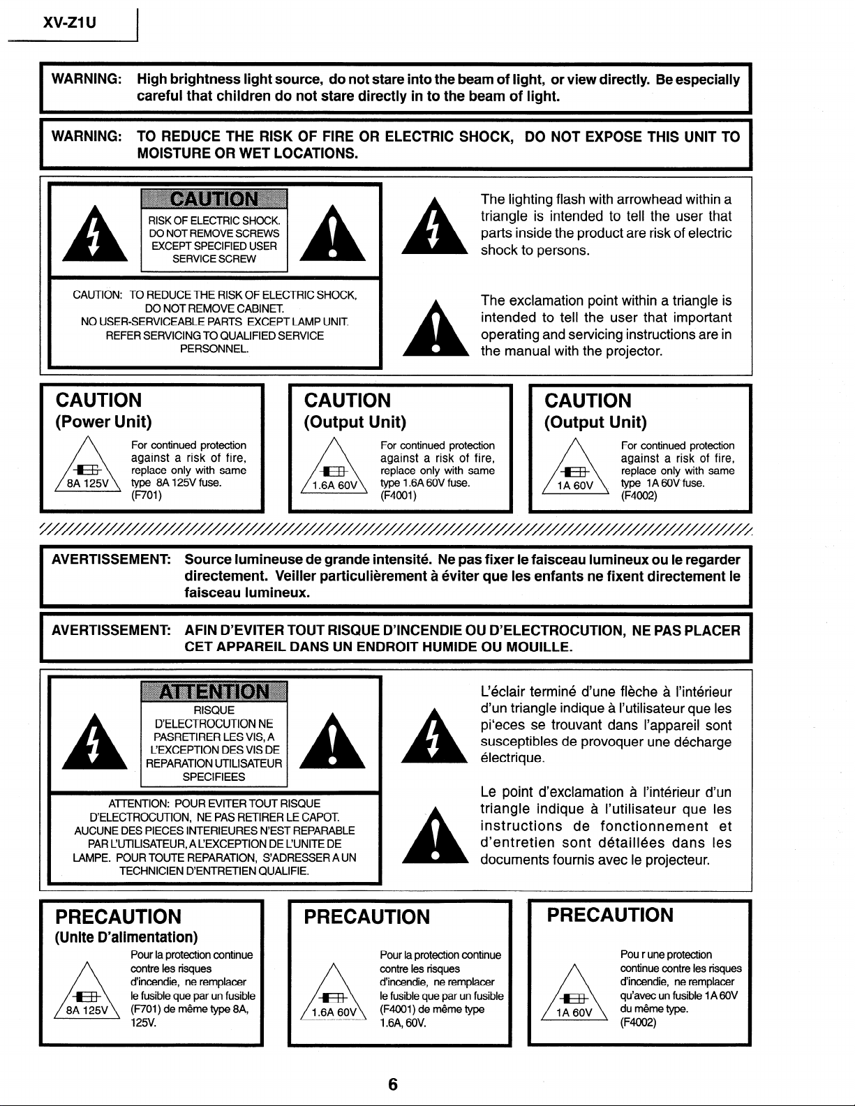
WARNING: High brightness light source, do not stare into the beam of light, or view directly. Be especially
careful that children do not stare directly in to the beam of light.
WARNING: TO REDUCE THE RISK OF FIRE OR ELECTRIC SHOCK, DO NOT EXPOSE THIS UNIT TO
MOISTURE OR WET LOCATIONS.
RISK OF ELECTRIC SHOCK.
DO NOT REMOVE SCREWS
EXCEPT SPECIFIED USER
SERVICE SCREW
A
The lighting flash with arrowhead within a
triangle is intended to tell the user that
parts inside the product are risk of electric
shock to persons.
CAUTION: TO REDUCE THE RISK OF ELECTRIC SHOCK,
DO NOT REMOVE CABINET
NO USER-SERVICEABLE PARTS EXCEPT LAMP UNIT
REFER SERVICING TO QUALIFIED SERVICE
PERSONNEL.
A
The exclamation point within a triangle is
intended to tell the user that important
operating and servicing instructions are in
the manual with the projector.
CAUTION
(Power Unit)
For continued protection
against a risk of fire,
replace only with same
type 8A l25V fuse.
(ROl)
CAUTION
(Output Unit)
For continued protection
against a risk of fire,
replace only with same
type 1.6A 60V fuse.
(F4OOl)
CAUTION
(Output Unit)
For continued protection
against a risk of fire,
replace only with same
type 1 A 6OVfuse.
(F4002)
AVERTISSEMENT: Source lumineuse de grande intensite. Ne pas fixer le faisceau lumineux ou le regarder
directement. Veiller particulierement a eviter que les enfants ne fixent directement le
faisceau lumineux.
I
AVERTISSEMENT: AFIN D’EVITER TOUT RISQUE D’INCENDIE OU D’ELECTROCUTION, NE PAS PLACER
CET APPAREIL DANS UN ENDROIT HUMIDE OU MOUILLE.
I
A
RISQUE
D’ELECTROCUTION NE
PASRETIRER LES VIS, A
L’EXCEPTION DES VIS DE
REPARATION UTILISATEUR
A
SPECIFIEES
ATTENTION: POUR EVITER TOUT RISQUE
D’ELECTROCUTION, NE PAS RETIRER LE CAPOT.
AUCUNE DES PIECES INTERIEURES N’EST REPARABLE
PAR L’UTILISATEUR, A L’EXCEPTION DE L’UNITE DE
LAMPE. POUR TOUTE REPARATION, S’ADRESSER A UN
TECHNICIEN D’ENTRETIEN QUALIFIE.
PRECAUTION PRECAUTION
(Unite D’alimentation)
Pour la protection continue
contre les risques
d’incendie, ne remplacer
le fusible que par un fusible
(F701) de meme type 8A,
l25V.
A
A
C&lair termine d’une fleche a l’interieur
d’un triangle indique a I’utilisateur que les
pi‘eces se trouvant dans I’appareil sont
susceptibles de provoquer une decharge
electrique.
Le point d’exclamation a I’interieur d’un
triangle indique a I’utilisateur que les
instructions de fonctionnement et
d’entretien sont detaillees dans les
documents fournis avec le projecteur.
Pour la protection continue
contre les risques
d’incendie, ne remplacer
le fusible que par un fusible
(F4001) de meme type
1.6A, 60V.
PRECAUTION
Pou r une protection
continue contre les risques
d’incendie, ne remplacer
qu’avec un fusible 1 A 60V
du meme type.
(F4002)
6
I
xv-z1 u
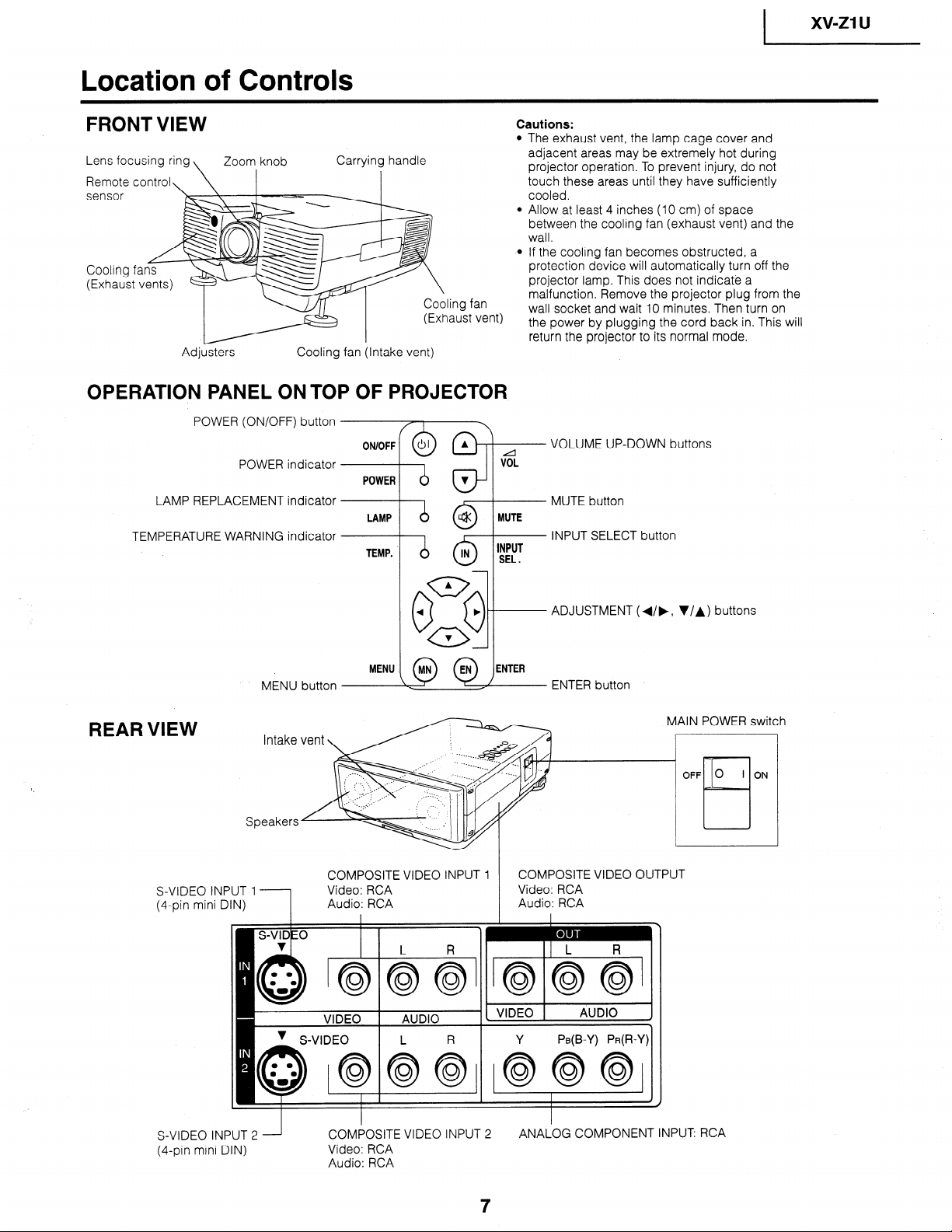
Location of Controls
FRONT VIEW
Cautions:
Lens focusing ring
Remote control,
\ Zoom, knob Carry in! handle
sensor
Cooling f
(Exhaust
ing fan
aust vent)
Adjusters Cooling fan (Intake vent)
OPERATION PANEL ON TOP OF PROJECTOR
POWER (ON/OFF) button
The exhaust vent, the lamp cage cover and
adjacent areas may be extremely hot during
projector operation. To prevent injury, do not
touch these areas until they have sufficiently
cooled.
Allow at least 4 inches (10 cm) of space
between the cooling fan (exhaust vent) and the
wall.
If the cooling fan becomes obstructed, a
protection device will automatically turn off the
projector lamp. This does not indicate a
malfunction. Remove the projector plug from the
wall socket and wait 10 minutes. Then turn on
the power by plugging the cord back in. This will
return the projector to its normal mode.
POWER indicator
LAMP REPLACEMENT indicator
TEMPERATURE WARNING indicator
ON/OFF
POWER
VOLUME UP-DOWN buttons
MUTE button
INPUT SELECT button
ADJUSTMENT (4/b, V/A) buttons
MENU button
ENTER button
REAR VIEW
Intake
Speakers
MAIN POWER switc
COMPOSITE VIDEO INPUT 1
COMPOSITE VIDEO OUTPUT
S-VIDEO INPUT 1
1
Video: RCA
Video: RCA
(4pin mini DIN)
Audio: RCA
Audio: RCA
I IjL R
Y PB(B-Y) PR(R-Y)
h
S-VIDEO INPUT 2
(4-pin mini DIN)
COMPOSITE VIDEO INPUT 2
ANALOG COMPONENT INPUT RCA
Video: RCA
Audio: RCA
xv-ZlU 1
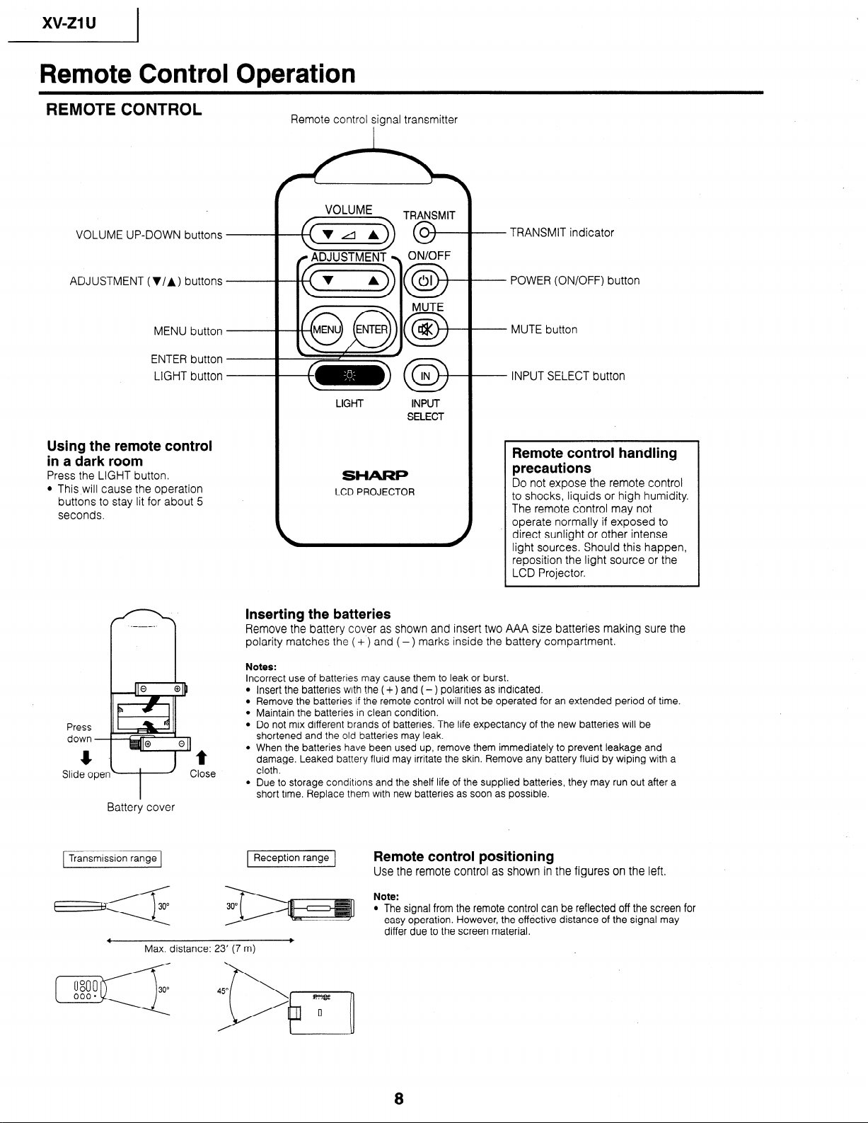
Remote Control Operation
REMOTE CONTROL
VOLUME UP-DOWN buttons
ADJUSTMENT (V/A) buttons
MENU button
ENTER button
LIGHT button
Using the remote control
in a dark room
Press the LIGHT button.
l This will cause the operation
buttons to stay lit for about 5
seconds.
Press
down -
Slide oper
Battery cover
1 Transmission range 1
t
Zlose
Remote control sianal transmitter
VOLUME
aTRF
ON/OFF
a
01
MUTE
0-
a
LIGHT INPUT
SELECT
SHARP
LCD PROJECTOR
- TRANSMIT indicator
- POWER (ON/OFF) button
- MUTE button
- INPUT SELECT button
Remote control handling
precautions
Do not expose the remote control
to shocks, liquids or high humidity.
The remote control may not
operate normally if exposed to
direct sunlight or other intense
light sources. Should this happen,
reposition the light source or the
LCD Projector.
L
Inserting the batteries
Remove the battery cover as shown and insert two AAA size batteries making sure the
polarity matches the ( + ) and (-) marks inside the battery compartment.
Notes:
Incorrect use of batteries may cause them to leak or burst.
Insert the batteries with the ( +) and (- ) polarities as indicated.
Remove the batteries if the remote control will not be operated for an extended period of time.
Maintain the batteries in clean condition.
Do not mix different brands of batteries. The life expectancy of the new batteries will be
shortened and the old batteries may leak.
When the batteries have been used up, remove them immediately to prevent leakage and
damage. Leaked battery fluid may irritate the skin. Remove any battery fluid by wiping with a
cloth.
Due to storage conditions and the shelf life of the supplied batteries, they may run out after a
short time. Replace them with new batteries as soon as possible.
Reception range
Remote control positioning
Use the remote control as shown in the figures on the left.
Note:
l The signal from the remote control can be reflected off the screen for
easy operation. However, the effective distance of the signal may
differ due to the screen material.
-
Max. distance: 23’ (7 m)
8
1 xv-mu
Demensions
Rear View
Top View
t-----
I
Side View
Front View
__!L
1.8 (45)
14
[Units: inches (mm)]
Bottom View
9
xv-21
u
I
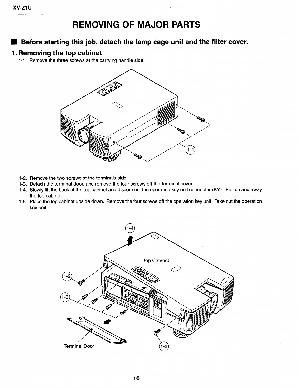
REMOVING OF MAJOR
PARTS>
n Before starting this job, detach the lamp cage unit and the filter cover.
1. Removing the top cabinet
l-l
. Remove the three
screws at the carrying
handle side.
1-2
.
1-3
.
1-4 .
l-5
.
Remove the two screws at the terminals side.
Detach the terminal door, and remove the four screws off the terminal cover.
Slowly lift the back of the top cabinet and disconnect the operation key unit connector (KY).
Pull up and away
the top cabinet.
Place the top cabinet upside down. Remove the four screws off the operation key unit. Take out the operation
key unit.
Terminal Door
10
I
xv-z1
u
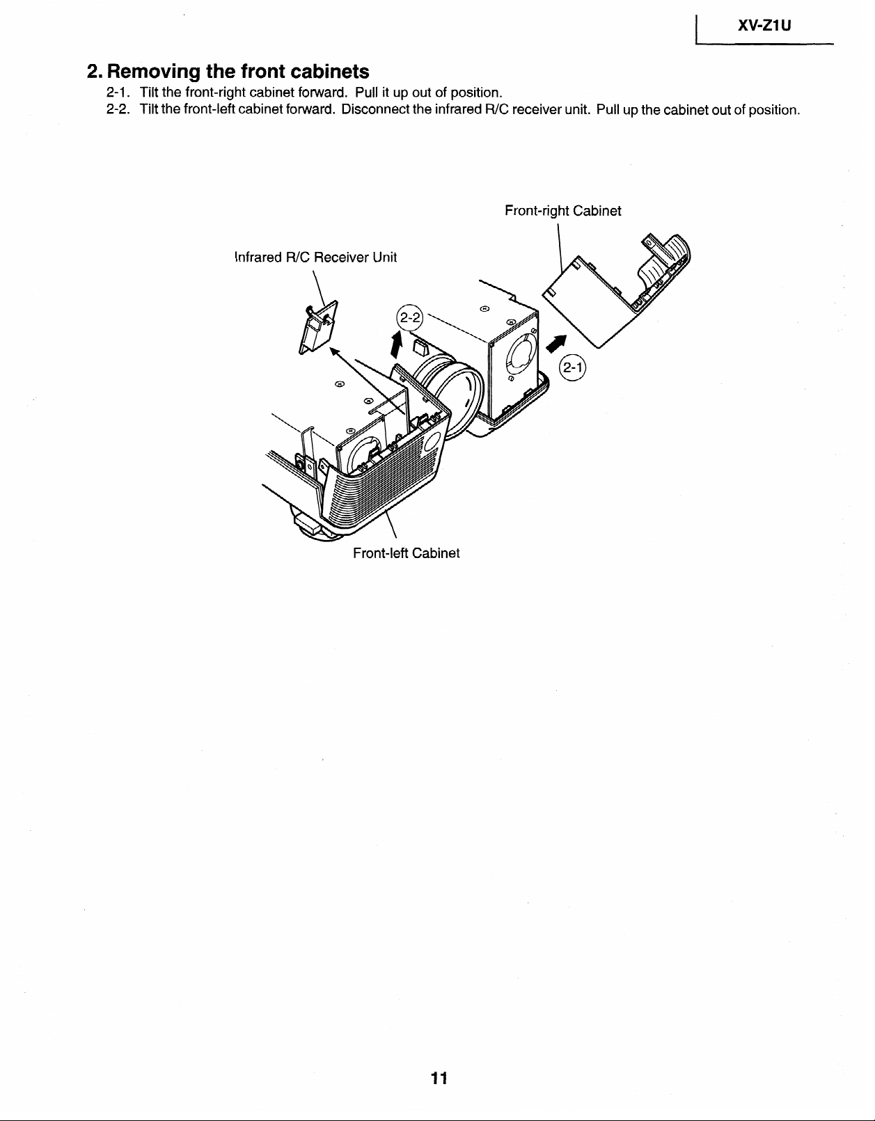
2. Removing the front cabinets
2-1. Tilt the front-right cabinet forward. Pull it up out of position.
2-2.
Tilt the front-left cabinet
forward. Disconnect the infrared R/C receiver unit. Pull up
the cabinet out of position.
Front-right Cabinet
lnfra
Front-left Cabinet
11
xv-21 u
I
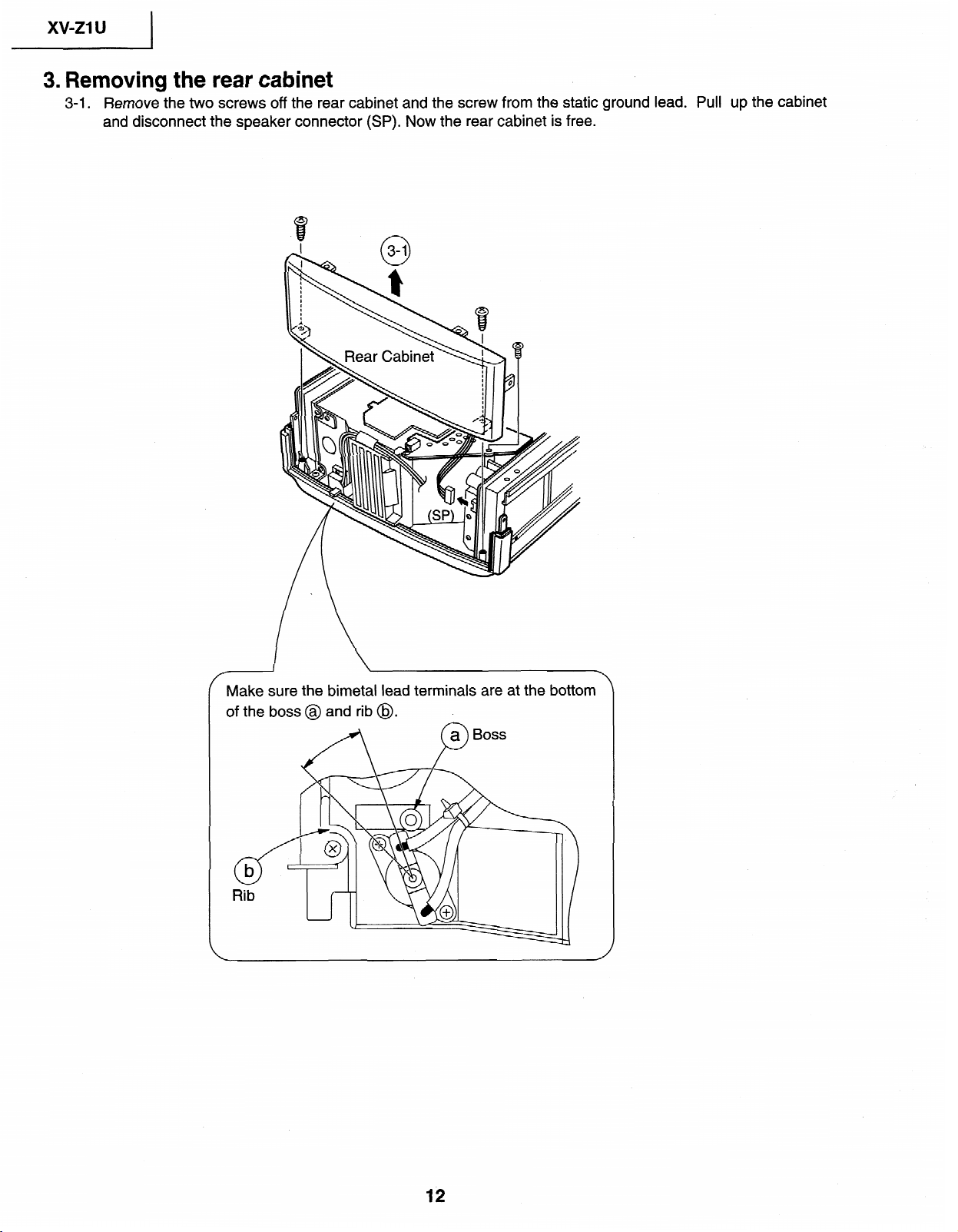
3. Removing the rear cabinet
3-1. Remove the two
screws
off the rear
cabinet
and
the
screw
from
the static ground lead. Pull up the cabinet
and
disconnect
the
speaker connector (SP). Now
the
rear
cabinet
is free.
Make sure the bimetai lead terminals are at the
bottom
of the boss@ and
rib @.
12
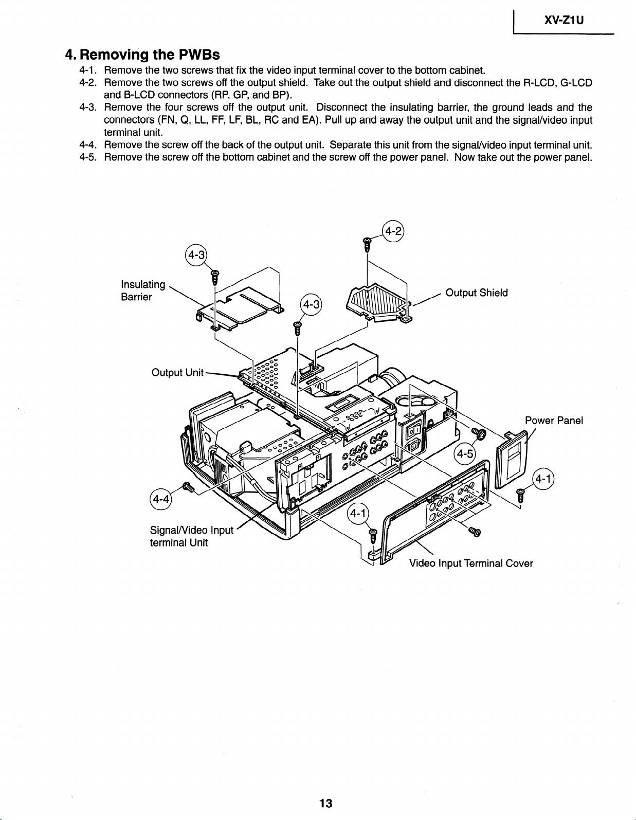
4. Removing the PWBs
1 xv-ZlU
4-1 .
4-2
.
4-3 .
Remove the two screws that fix the video input terminal cover to the bottom cabinet.
Remove the two screws off the output shield. Take out the output shield and disconnect the R-LCD, G-LCD
and B-LCD connectors (RP, GP, and BP).
Remove the four screws off the output unit. Disconnect the insulating barrier, the ground leads and the
connectors (FN, Q, LL, FF, LF, BL, RC and EA). Pull up and away the output unit and the signal/video input
terminal unit.
4-4 . Remove the screw off the back of the output unit. Separate this unit from the signal/video input terminal unit.
4-5 . Remove the screw off the bottom cabinet and the screw off the power panel. Now take out the power panel.
lnsula
Barrie
ting
r
Output Shield
Signal/Video Input
terminal Unit
Panel
13
xv-z1 u
I
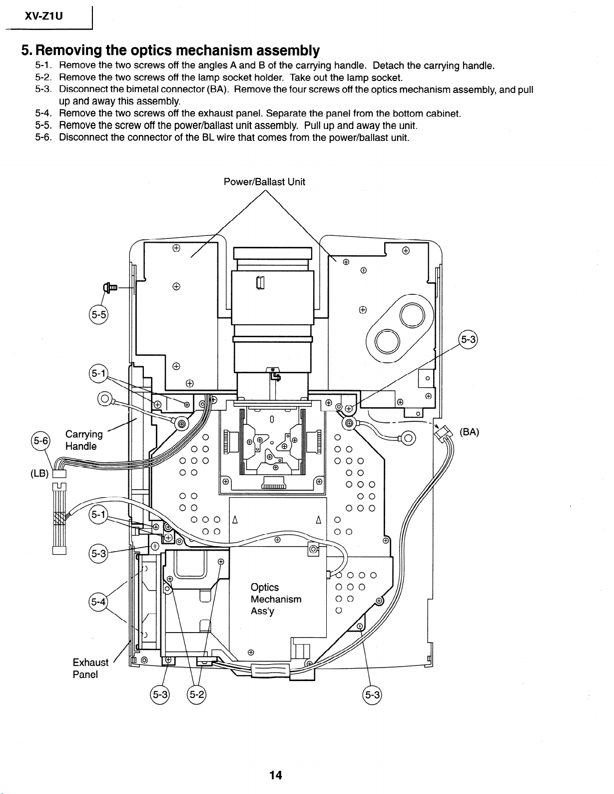
5. Removing the optics mechanism assembly
5-l
.
5-2
.
5-3 .
5-4
.
5-5 .
5-6
.
Q
5-6
Remove the two screws off the angles A and B of the carrying handle.
Detach the carrying handle.
Remove the two screws off the lamp socket holder. Take out the lamp socket.
Disconnect the bimetal connector (BA).
Remove the four screws off the optics mechanism assembly, and pull
up and away this assembly.
Remove the two screws off the exhaust panel. Separate the panel from the bottom cabinet.
Remove the screw off the power/ballast unit assembly. Pull up and away the unit.
Disconnect the connector of the BL wire that comes from the power/ballast unit.
Power/Ballast Unit
Exhaust
/
Panel
14
xv-z1 u
CONTROLLING THE TOTAL OPERATING HOURS OF THE LAMP
The following control is carried out when the lamp has been used for 1900 hours and 2000
hours.
1 .
2 .
3 .
4 .
After 1900-hour use
When the power is turned on, “LAMP” appears in the on-screen display for about 1 minute (flashing in yellow)
and the lamp LED indicator lights up in red. When the 1,900-hour point comes up during use of the unit, the
“LAMP” display starts flashing in yellow on the screen for 1 minute at the very 1,900-hour point. Now the lamp
LED indicator changes from green to red.
After 2000-hour use
When the power is turned on, “LAMP” appears in the on-screen display for about 5 minutes (flashing in red) and
the lamp LED indicator lights up in red. Five minutes thereafter, the power turns itself off and the unit is interrupted.
When the 2000-hour point comes up during use of the unit, the “LAMP” display starts flashing in red on the
screen for 5 minutes at the very 2000-hour point. Five minutes later, the power turns itself off and the unit is
interrupted. (The lamp LED indicator stays red since the 1900-hour point.)
If you try to turn on the power three times after the 2000-hour point, the unit remains off.
When the 2000-hour point comes up, take the following steps.
Replace the lamp with new one. While holding down both the “V0L.v” and “ADJY” keys on the unit, turn on
the main power switch (located on the side of the unit). The lamp operating hourmeter is now reset to zero. Turn
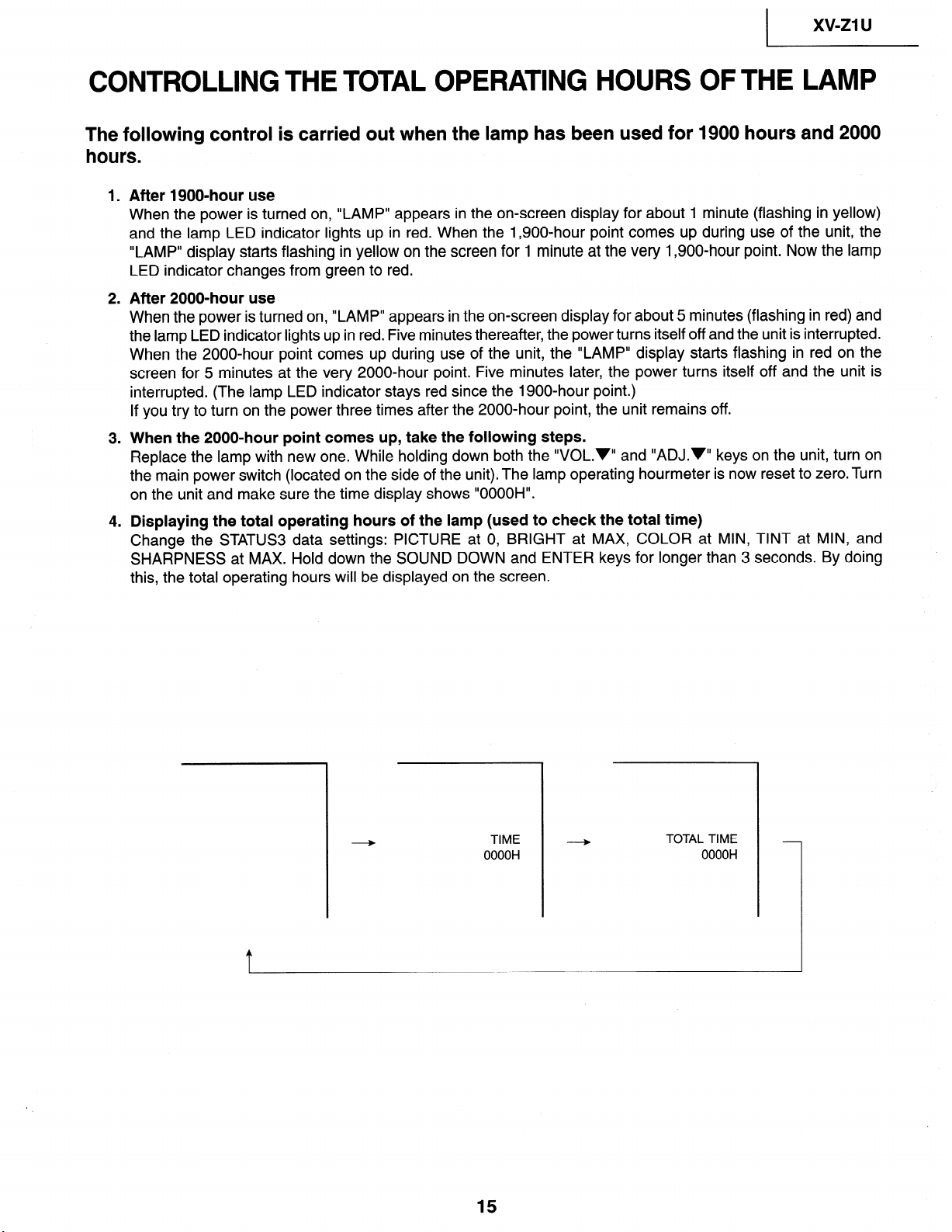
on the unit and make sure the time display shows “OOOOH”.
Displaying the total operating hours of the lamp (used to check the total time)
Change the STATUS3 data settings: PICTURE at 0, BRIGHT at MAX, COLOR at MIN, TINT at MIN, and
SHARPNESS at MAX. Hold down the SOUND DOWN and ENTER keys for longer than 3 seconds. By doing
this, the total operating hours will be displayed on the screen.
15
1 xv-ZlU
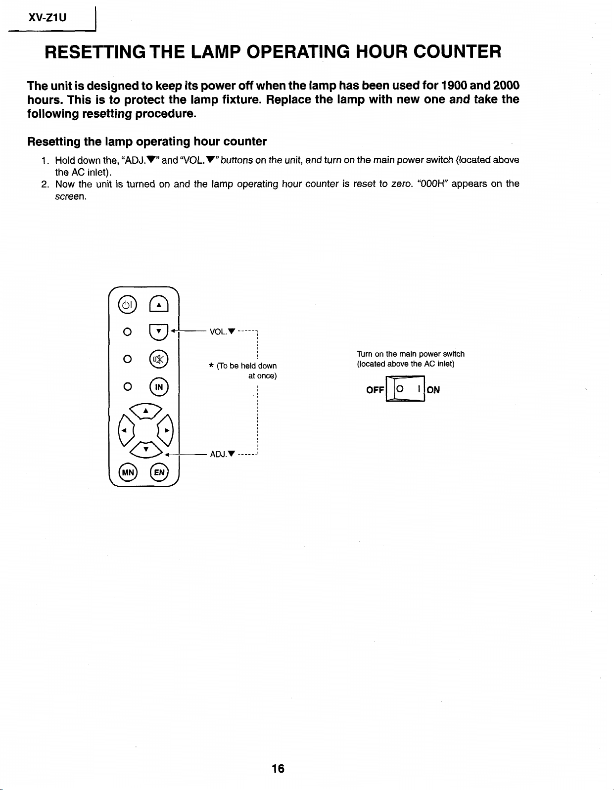
RESETTING THE LAMP OPERATING HOUR COUNTER
The unit is designed to keep its power off when the
lamp has been
used for
1900
and
2000
hours.
This is to protect the lamp fixture. Replace the lamp with new one and take the
following resetting procedure.
Resetting the lamp operating hour counter
1.
Hold down the, “ADJ.v” and “V0L.v” buttons on the unit, and
turn
on the main power
switch (located above
the AC inlet).
2. Now the
unit is
turned on and the
lamp operating hour counter
is reset to zero. “OOOH” appears on
the
screen.
0 @
0 @
* (To be held down
at once)
I
I
I
’
I
I
I
I
I
I
I
I
I
I
I
I
I
I
ADJ.v _____s.~
Turn on the main power switch
(located above the AC inlet)
16
_ xv-ZlU
1
CONVERGENCE AND FOCUS ADJUSTMENT
l
Start the convergence
and focus adjustments with the top cabinet and the signal shield
removed but the power on. Use the remote control gun to adjust the image.Take the
following procedures.
1. Focusing the projection lens
(A) Replacing all the 3 LCD panels
1.
Before
replacing all the 3 LCD panels,
project an image on the screen and bring it into focus.
2. Replace the
panels with
new
ones. But
until
the focus
has been completely readjusted,
be
careful not to
change the distance between the set and the
screen, nor to move
the projection
lens focus and zoom
rings.
If
the
focus
is
readjusted with a different positional relation, the relation between the projection
distance
and the screen size is affected. In
other words, a short-distance image (40 WIDE, for example) may
get
out of the focus range, or a
long-distance
image (300
WIDE,
for example) may come out of focus.
(B) Replacing
1 or 2 of the 3 LCD panels
1. In adjusting
the focus after replacement of one or two LCD
panels, project
an image on the screen and turn
the projection lens focus ring to get the non-replaced LCD panel into focus.
2. But until the focus has been completely adjusted for the new LCD panels, be careful not to change the
distance between the set and the screen, nor to move the projection lens focus and zoom rings.
(If
the distance has been changed or the projection lens readjusted, repeat the above steps 1 and 2.)
2. Adjusting the G-LCD panel
(A) Focus adjustment. (Make this adjustment on the white-only screen.)
1. Right-and-left focus adjustment (0Y direction) .
Loosen the lock screws “b” and “c” and insert the eccentric screwdriver into the notch and hole ‘lb”. Turn
the screwdriver until the right and left halves on the screen get into focus.
First get the right and left halves in balance. Then improve the accuracy while making the adjustment 2
below.
2 .
3
.
‘Top-center-bottom focus adjustment (0X and Z directions).
Loosen the lock screws “a” and “c”
and insert the eccentric screwdriver into the notch and hole “a” or “c”.
Turn the screwdriver until the top, center and bottom on the screen get into focus. In adjusting this top-to-
bottom focus, temporarily tighten the lock screw “b” to fix the 8Y direction adjustment.
Repeat the above steps 1 and 2 to finely adjust the focus.
Finally tighten up all the lock screws.
Note
:
@ Carefully proceed with the focus adjustment because the adjusting directions are correlated.
@ In adjusting the convergence and focus, do not move the projection lens zoom and focus rings until the end
of all the adjustments.
(B) Convergence adjustment
l
The G-LCD panel has no convergence adjustment mechanism. Use this panel as convergence adjustment
reference.
3. B-LCD panel adjustment (the same for the R-LCD panel)
(A) Focus adjustment
l Take the same procedure as for the G-LCD panel focus adjustment. Note that the adjustment range is small
in the Z direction. If the convergence is quite different between the B-LCD and G-LCD panels, roughly adjust
the convergence first and then the focus.
(B) Convergence adjustment
l Use a crosshatch pattern signal for this adjustment.
Make the adjustment just for the G-color and the relevant color.
(1)
(2)
(3)
Loosen the convergence lock screw “d”.
With the G-LCD panel’s screen center as reference, adjust the B-LCD panel in the X, Y and 8Z directions.
Finally tighten up the convergence lock screw I’d”.
18
1 xv-ZllJ
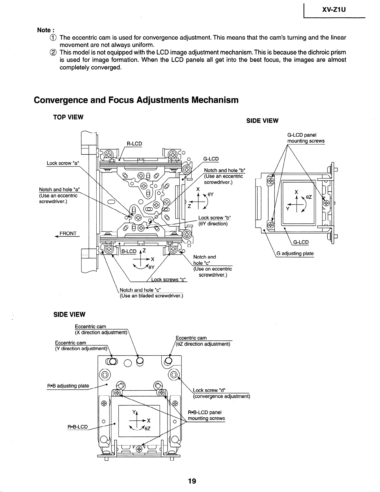
Note :
@ The eccentric cam is used for convergence adjustment. This means that the cam’s turning and the linear
movement are not always uniform.
@ This model is not equipped with the LCD image adjustment mechanism.This is because the dichroic prism
is used for image formation. When the LCD panels all get into the best focus, the images are almost
completely converged.
Convergence and Focus Adjustments Mechanism
TOP VIEW
SIDE VIEW
r
h
-r-I
R-LCD
Lock screw “a”
Notch and hole “a”
(Use an eccentric \
screwdriver.)
FRONT
0 G-LCD
Lock screw “b”
(0Y direction)
\ Notch and hole “c”
(Use an bladed screwdriver.)
Eccentric cam
(y direct.;\
Eccentnc cam
ROB adjusting plate ,
Lock screw “d”
(convergence adjustment)
G-LCD panel
mounting screws
\G adjusting plate
xv-ZlU 1
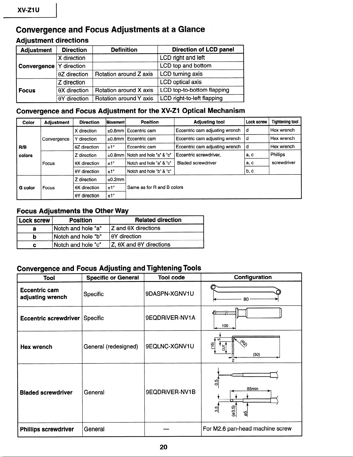
Convergence and Focus Adjustments at a Glance
Adjustment directions
Adjustment Direction
Definition
Direction of LCD panel
X direction
LCD right and left
Convergence Y direction
LCD top and bottom
0Z direction
Rotation around Z axis LCD turning axis
Z direction
LCD optical axis
Focus
8X direction Rotation around X axis LCD top-to-bottom flapping
8Y direction Rotation around Y axis LCD right-to-left flapping
,
Convergence and Focus Adjustment for the XV-Z1 Optical Mechanism
Color Adjustment Direction Movement
Position
Adjusting tool Lock screw Tightening tool
X direction *0.8mm Eccentric cam
Eccentric cam adjusting wrench
d
Hex wrench
Convergence Y direction k0.8mm Eccentric cam
Eccentric cam adjusting wrench d
Hex wrench
R/B
0Z direction
=tl O
Eccentric cam
Eccentric cam adjusting wrench
d
Hex wrench
colors
Z direction =t0.8mm Notch and hole “a” & “c” Eccentric screwdriver,
a, c
Phillips
Focus
0X direction A0
Notch and hole “a” & “c” Bladed screwdriver
a’ c
screwdriver
8Y direction ~1”
Notch and hole “b” & “c”
b, c
G color
Same as for R and B colors
Focus Adjustments the Other Way
Lock screw Posit ion
Related direction
a
Notch and hole “a” Z and 6X directions
I---
b
1 Notch and hole “b” I8Y direction
. I
I C 1 Notch and hole “c” 1 Z, 0X and 8Y directions
I
Convergence and Focus Adjusting and Tightening Tools
-
-
Tool
Specific or General
Tool code
Configuration
Eccentric cam
adjusting wrench
Specific
9DASPN-XGNVl U
TT?
Eccentric screwdriver Specific
SEQDRiVER-NVlA
Hex wrench
General (redesigned)
SEQLNC-XGNVl U
2
,LL
Lc!
Bladed screwdriver
General
SEQDRiVER-NV1 B
t f
85min +,
j=$+j-
Phillips screwdriver General
For M2.6 pan-head machine screw
I
xv-21
u
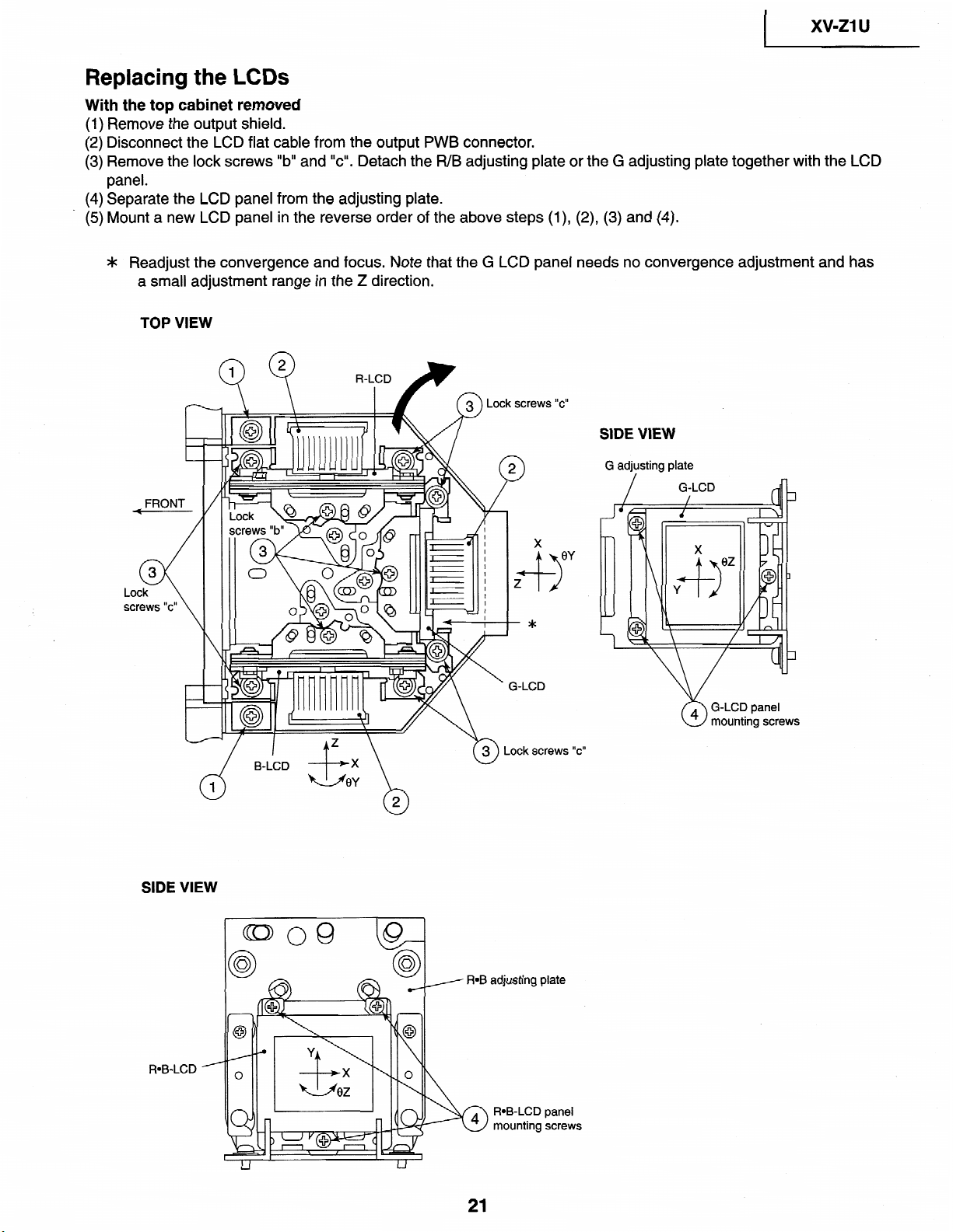
Replacing the LCDs
With the top cabinet removed
(1) Remove the output shield.
(2) Disconnect the LCD flat cable from the output PWB connector.
(3) Remove the lock screws “b” and
“c”. Detach the R/B adjusting plate or the G adjusting plate together with the LCD
panel.
(4) Separate the LCD panel from the adjusting plate.
* (5) Mount a new LCD panel in
the reverse order of the above steps (l), (2), (3) and (4).
* Readjust the convergence and
focus. Note that the G LCD
panel
needs
no convergence adjustment
and has
a small adjl
_rstment range in the Z direction.
TOP VIEW
pews
“C”
SIDE VIEW
.CD
fz \
m Lock screws “c”
d
B-LCD
1
SIDE VIEW
ROB-LCD
adjusting plate
ROB-LCD panel
mounting screws
G adjusting plate
G-LCD
/
xv-21
u
I
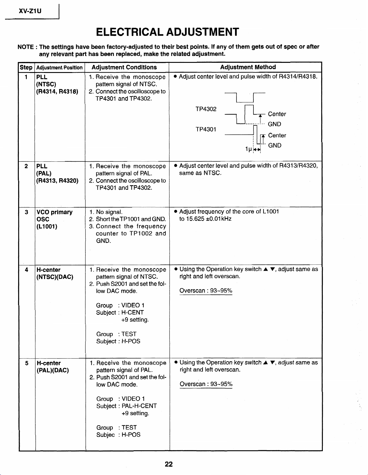
ELECTRICAL ADJUSTMENT
NOTE :
The settings
have been factory-adjusted to their
best
points.
If any of them gets out of
spec
or after
any relevant
part has been
replaced, make
the
related adjustment.
Step
Adjustment
Position Adjustment
Conditions
Adjustment Method
1 PLL
1. Receive the monoscope
l
Adjust center level
and pulse width of R4314/R4318.
(NTSC)
pattern signal of NTSC.
(R4314,
R4318)
2. Connect the oscilloscope to
TP4301 and
TP4302.
TP4302
x
Center
TP4301
.+
iinIer
I
I
2
PLL
1. Receive the monoscope
l
Adjust
center
level and pulse width of R4313/R4320,
(PAL)
pattern signal
of PAL.
same as NTSC.
(I?431 3, R4320)
2.
Connect the oscilloscope to
TP4301 and TP4302.
3
VCO primary
osc
(Ll 001)
1. No signal.
l Adjust frequency of the core
of LlOOl
2. Short theTPlOO1 and GND.
to 15.625 kO.01 kHz
3. Connect the frequency
counter to TP1002 and
GND.
4
H-center
(NTSC)( DAC)
1. Receive the
monoscope
l
Using the Operation key switch A ‘I, adjust same as
pattern signal of NTSC.
right and left overscan.
2. Push S2001 and set the fol-
low DAC mode.
Overscan : 93-95%
Group
: VIDEO
1
Subject : H-CENT
+9 setting.
Group
: TEST
Subject : H-POS
5
H-center
(PAL)( DAC)
1. Receive the monoscope
l
Using the Operation key switch A v, adjust same as
pattern signal of PAL.
right and left overscan.
2. Push S2001 and set the fol-
low DAC mode.
Overscan : 93-95%
Group
: VIDEO 1
Subject : PAL-H-CENT
+9 setting.
Group : TEST
Subjec : H-POS
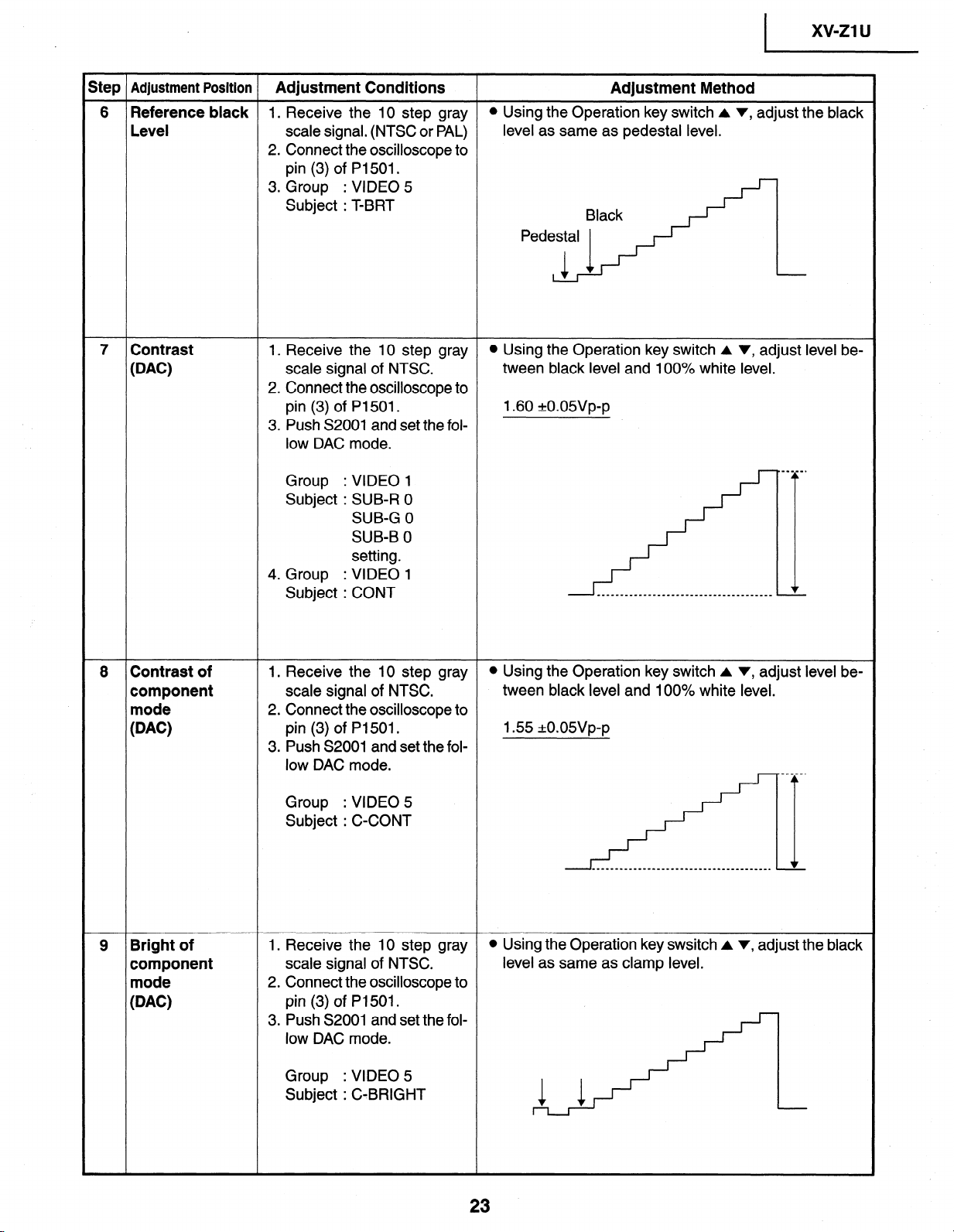
1 xv-ZlU
Step Adjustment Position
Adjustment Conditions
Adjustment Method
6 Reference black 1. Receive the 10 step gray
l Using the Operation key switch A v, adjust the black
Level scale signal. (NTSC or PAL)
level as same as pedestal level.
2. Connect the oscilloscope to
pin (3) of P1501.
3. Group : VIDEO 5
Subject : T-BRT
Ped;?: .:,’
7 Contrast
WC)
1. Receive the 10 step gray
l Using the Operation key switch A v, adjust level be-
scale signal of NTSC.
tween black level and 100% white level.
2. Connect the oscilloscope to
pin (3) of P1501.
1.60 kO.OWp-p
3. Push S2001 and set the fol-
low DAC mode.
Group : VIDEO 1
Subject : SUB-R 0
SUB-G 0
SUB-B 0
setting.
4. Group : VIDEO 1
Subject : CONT
8 Contrast of
component
mode
WC)
1. Receive the 10 step gray
l Using the Operation key switch A v, adjust level be-
scale signal of NTSC.
tween black level and 100% white level.
2. Connect the oscilloscope to
pin (3) of P1501.
1.55 -r-o.o5vp-p
3. Push S2001 and set the fol-
low DAC mode.
Group : VIDEO 5
Subject : C-CONT
9 Bright of
component
mode
WC)
1. Receive the 10 step gray
l Using the Operation key swsitch A v, adjust the black
scale signal of NTSC.
level as same as clamp level.
2. Connect the oscilloscope to
pin (3) of P1501.
3. Push S2001 and set the fol-
low DAC mode.
I
Group
: VIDEO 5
Subject : C-BRIGHT
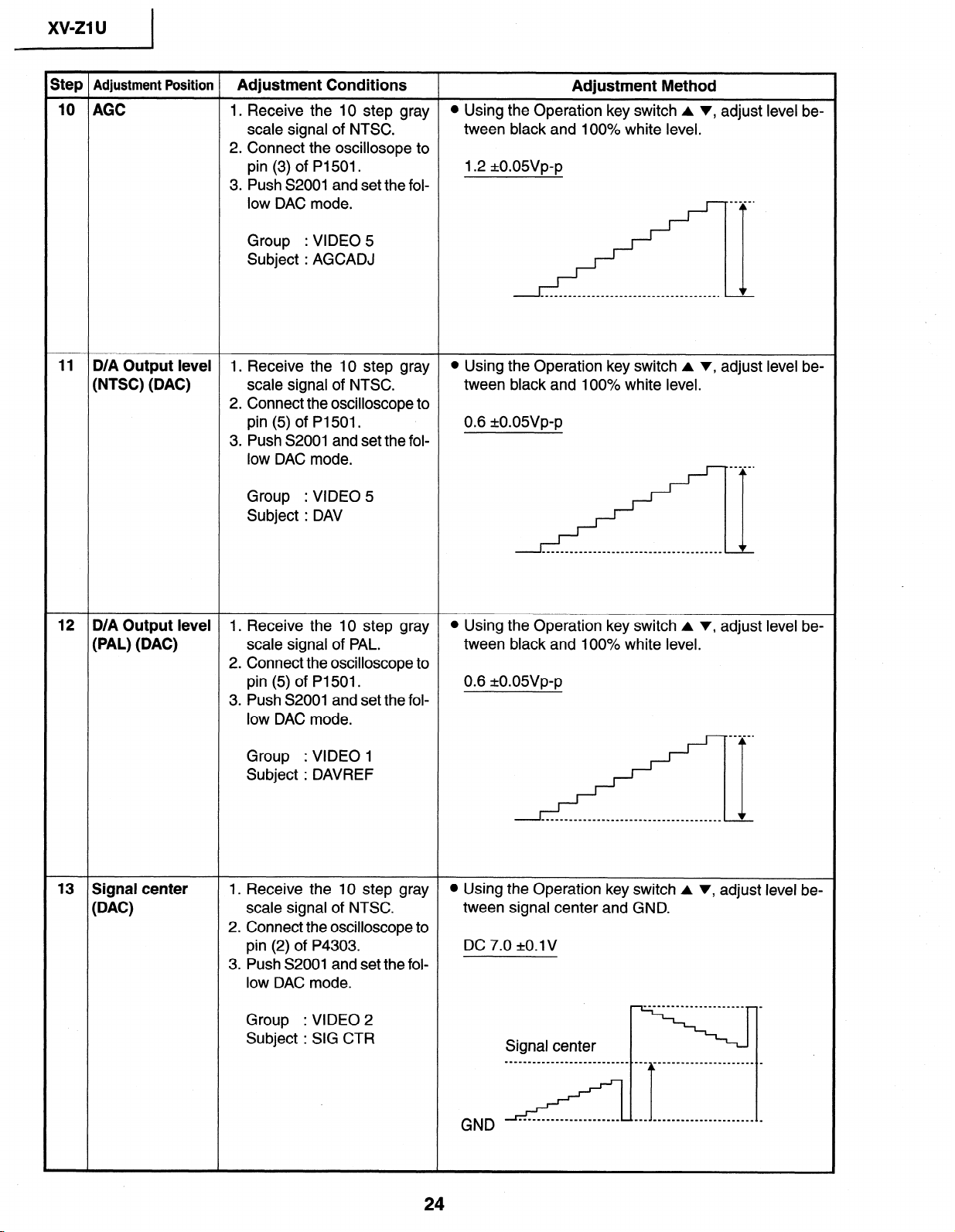
Step Adjustment Position Adjustment Conditions
Adjustment Method
10 AGC I. Receive the IO step gray
l Using the Operation key switch A v, adjust level be-
scale signal of NTSC.
tween black and 100% white level.
2. Connect the oscillosope to
pin (3) of PI 501.
1.2 *O.OWp-p
3. Push S2001 and set the fol-
low DAC mode.
Group : VIDEO 5
Subject : AGCADJ
‘i
_------_______________________________I
11 D/A Output level
I. Receive the 10 step gray
l Using the Operation key switch A v, adjust level be-
(NTSC) (DAC) scale signal of NTSC.
tween black and 100% white level.
2. Connect the oscilloscope to
pin (5) of Pl501.
0.6 +-O.OSVp-p
3. Push S2001 and set the fol-
low DAC mode.
Group : VIDEO 5
Subject : DAV
12 D/A Output level 1. Receive the 10 step gray
l Using the Operation key switch A v, adjust level be-
(PAL) (DAC)
scale signal of PAL.
tween black and 100% white level.
2. Connect the oscilloscope to
pin (5) of PI 501.
0.6 kO.O5Vp-p
3. Push S2001 and set the fol-
low DAC mode.
Group
: VIDEO 1
Subject : DAVREF
13 Signal center
WC)
1. Receive the 10 step gray
0 Using the Operation key switch A v, adjust level be-
scale signal of NTSC.
tween signal center and GND.
2. Connect the oscilloscope to
pin (2) of P4303.
DC 7.0 1t0.lV
3. Push S2001 and set the fol-
low DAC mode.
Group
: VIDEO 2
Subject : SIG CTR
Signal center
----________________--~~~--.--~
GND
24
I
xv-z1
u
Step
Adjustment Position
Adjustment Conditions
Adjustment Method
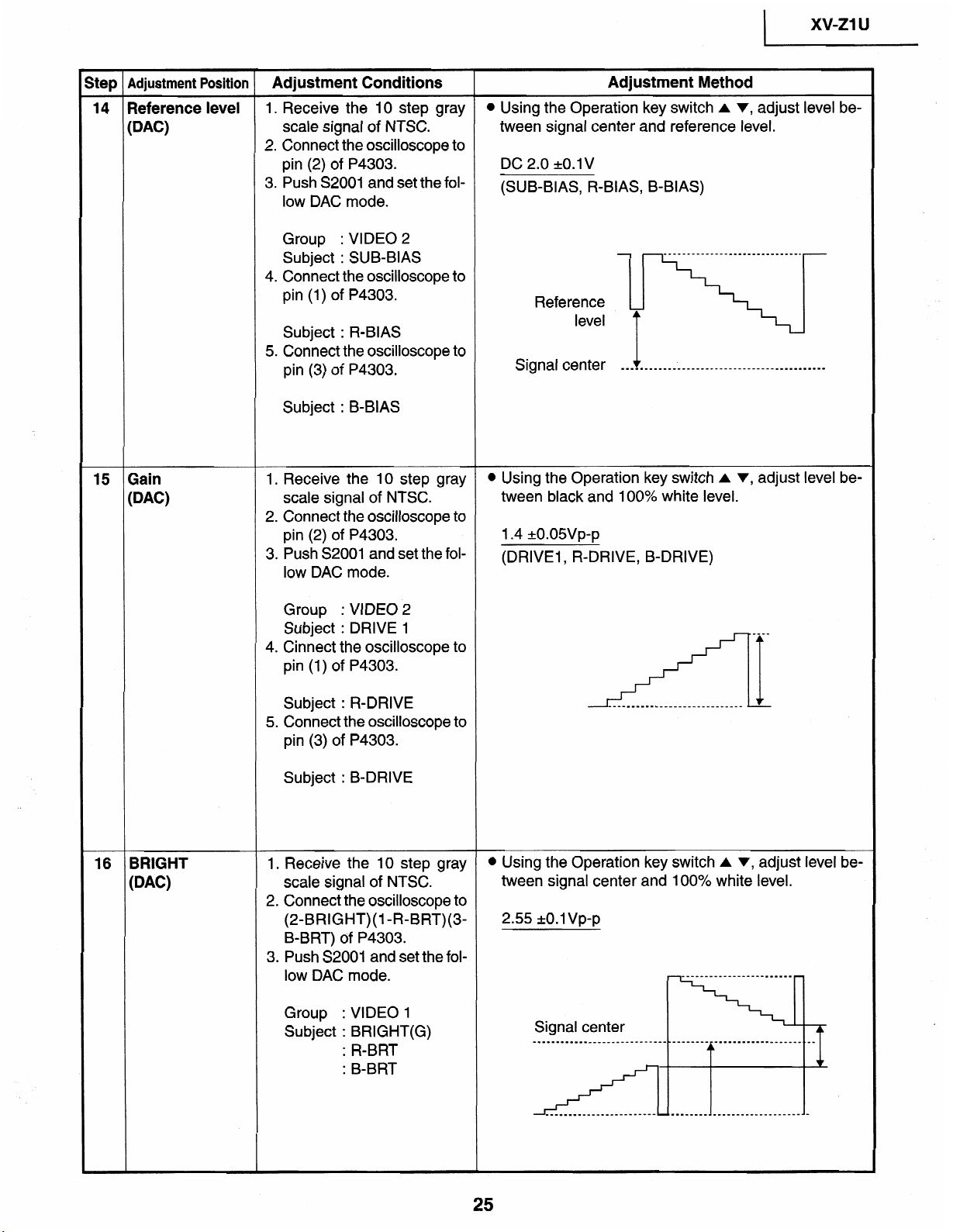
14 Reference level
1.
Receive the 10
step
gray
l
Using the Operation key switch A v, adjust level be-
WC)
scale signal
of NTSC.
tween signal center and reference level.
2. Connect the oscilloscope to
pin
(2) of P4303.
DC 2.0
+O.lV
3. Push
S2001 and set the fol-
(SUB-BIAS, R-BIAS, B-BIAS)
low
DAC mode.
Group
: VIDEO
2
Subject
: SUB-BIAS
4. Connect the oscilloscope to
pin
(1) of P4303.
Subject
:
R-BIAS
5. Connect the oscilloscope to
pin (3) of P4303.
Subject
: B-BIAS
______-_____________---------.
Reference
level
+
Signal
center -
________________________________________----
15
Gain
WC)
1. Receive the 10 step gray
0 Using the Operation key switch A v, adjust level be-
scale signal of NTSC.
tween black and 100% white level.
2. Connect the oscilloscope to
pin (2) of P4303.
1.4 *O.OWp-p
3. Push S2001 and set the fol-
(DRIVEl, R-DRIVE, B-DRIVE)
low DAC mode.
Group
: VIDEO 2
Subject : DRIVE
1
4. Cinnect the oscilloscope to
pin (1) of P4303.
Subject : R-DRIVE
5. Connect the oscilloscope to
pin (3) of P4303.
Subject : B-DRIVE
16
BRIGHT
WC)
1. Receive the 10 step gray
l
Using the Operation key switch A v, adjust level be-
scale signal of NTSC.
tween signal center and 100% white level.
2. Connect the oscilloscope to
(2=BRIGHT)(l -R=BRT)(3-
2.55 ~0.1 Vp-p
B-BRT) of P4303.
3. Push S2001 and set the fol-
low DAC mode.
Group : VIDEO 1
Subject : BRIGHT(G)
: R-BRT
: B-BRT
Signal center
____--______________---------.-------
xv-21 u
I
Step Adjustment Position Adjustment Conditions
Adjustment Method
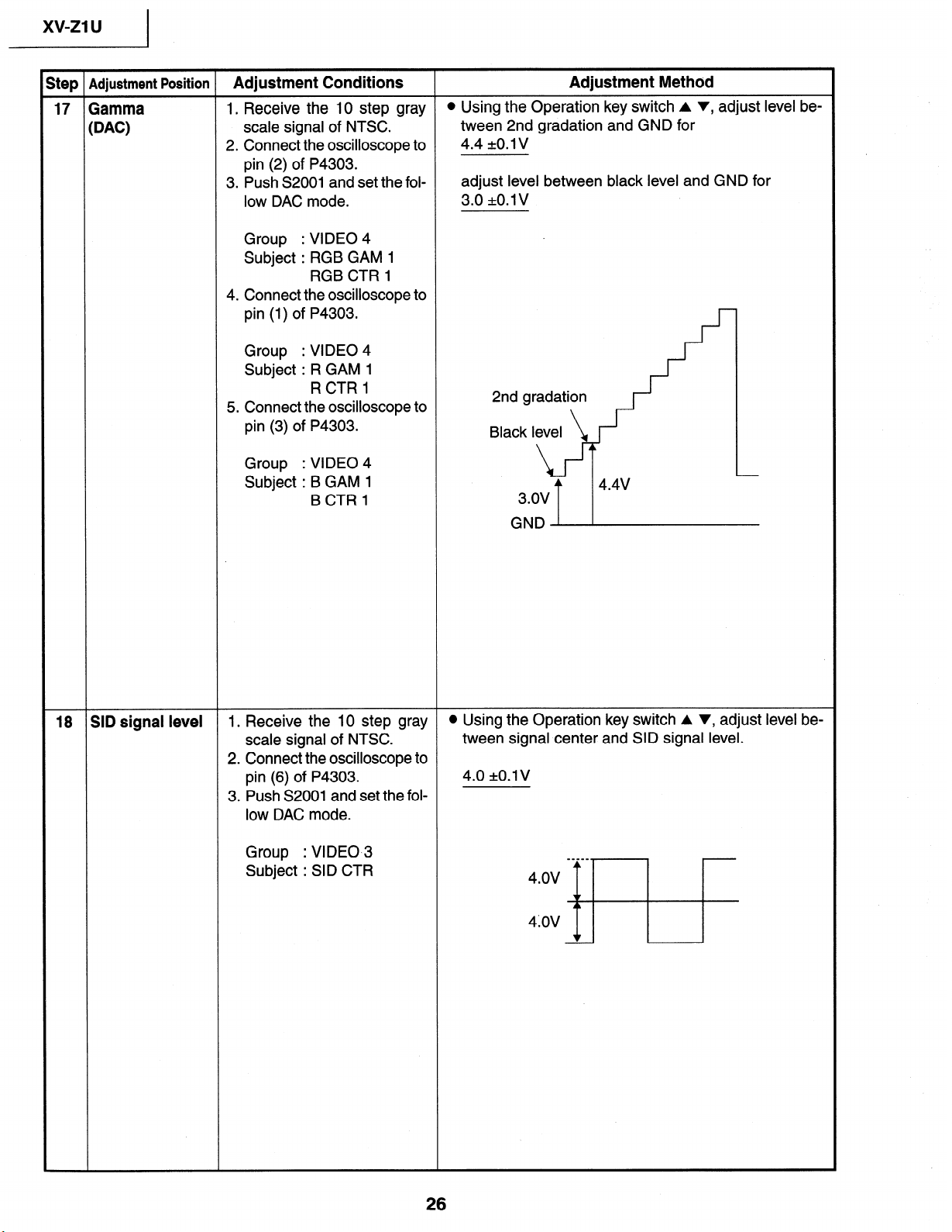
17 Gamma
1. Receive the 10 step gray
l Using the Operation key switch A v, adjust level be-
WC)
scale signal of NTSC.
tween 2nd gradation and GND for
2. Connect the oscilloscope to
4.4 kO.1 v
pin (2) of P4303.
3. Push S2001 and set the fol-
low DAC mode.
Group
: VIDEO 4
Subject : RGB GAM 1
RGB CTR 1
adjust level between black level and GND for
3.0 &O.lV
4. Connect the oscilloscope to
pin (1) of P4303.
Group
: VIDEO 4
Subject : R GAM 1
RCTRl
5. Connect the oscilloscope to
pin (3) of P4303.
Group
: VIDEO 4
Subject : B GAM 1
BCTRl
4
4.4v
3.ov
GND
18 SID signal level 1. Receive the 10 step gray
l Using the Operation key switch A v, adjust level be-
scale signal of NTSC.
tween signal center and SID signal level.
2. Connect the oscilloscope to
pin (6) of P4303.
4.0 *O.lV
3. Push S2001 and set the fol-
low DAC mode.
Group
: VIDEO.3
Subject : SID CTR
step
Adjustment Position
Adjustment Conditions Adjustment Method
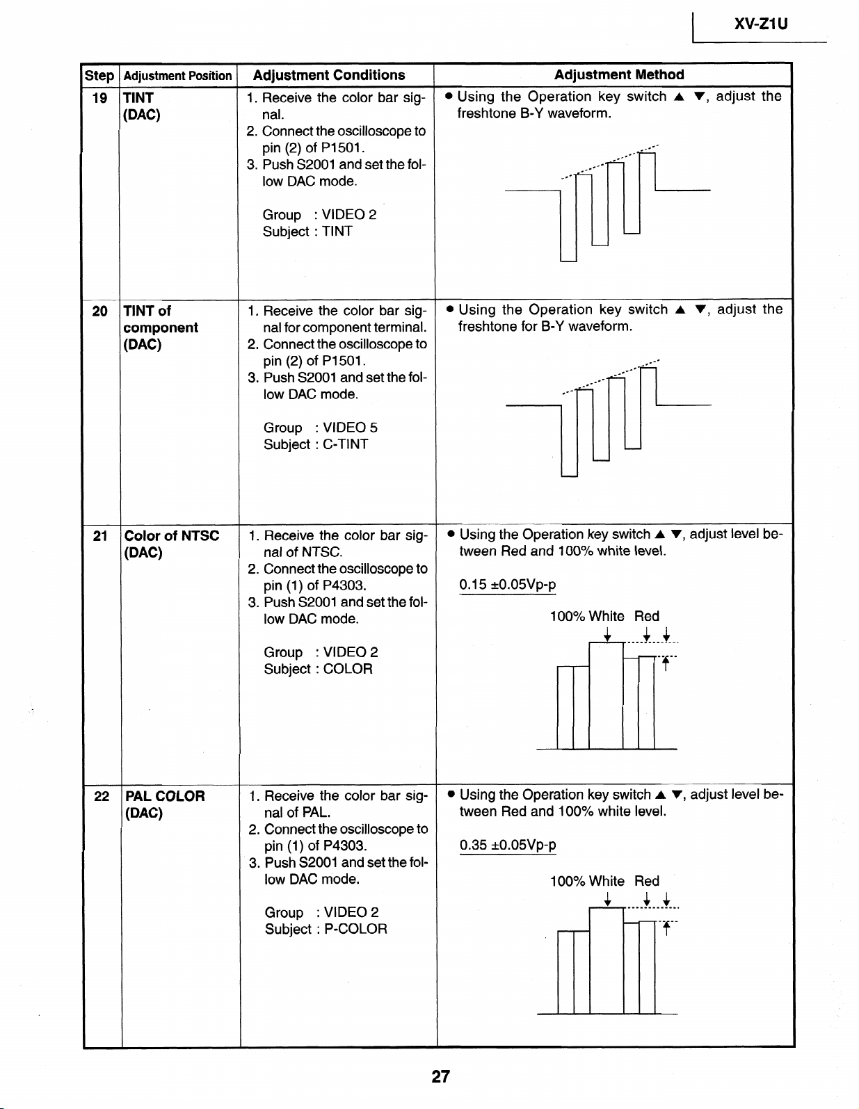
19 TINT
1.
Receive the
color
bar
sig-
l
Using the Operation key switch A
v, adjust the
(DAC)
nal.
freshtone B-Y waveform.
2.
Connect the oscilloscope
to
pin
(2)
of P1501.
3. Push
S2001
and set the fol-
low DAC mode.
Group : VIDEO
2
Subject : TINT
20
TINT of
component
@AC)
1. Receive the
color
bar
sig-
l
Using
the Operation key switch A v,
adjust the
nal for
component terminal.
freshtone for
B-Y waveform.
2.
Connect
the oscilloscope to
pin
(2)
of P1501.
_e--
c
c--
3. Push S2001 and set the fol-
low DAC mode.
Group
: VIDEO 5
Subject : C-TINT
21 Color
of NTSC
1. Receive the color bar sig-
l
Using the Operation key switch A v, adjust level be-
@AC)
nal of NTSC.
tween Red and 100% white level.
2. Connect the oscilloscope to
pin (1) of P4303.
0.15 +o.osvp-p
3. Push S2001 and set the fol-
low DAC mode.
100% White Red
$_ 44
_________M__.
Group
: VIDEO 2
__ -_
Subject : COLOR
-’
*f
22 PAL COLOR
@AC)
1. Receive the color bar sig-
l Using the Operation key switch A v, adjust level be-
nal of PAL.
tween Red and 100% white level.
2. Connect the oscilloscope to
pin (1) of P4303.
0.35 *o.o5vp-p
3. Push S2001 and set the fol-
low DAC mode.
100% White Red
Group
: VIDEO 2
&_ $4
____________.
__ -_
Subject : P-COLOR
- -f
27
xv-z1 u
I
Step Adjustment Position Adjustment Conditions Adjustment Method
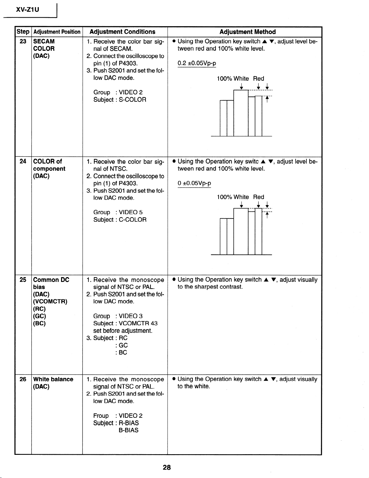
23 SECAM 1. Receive the color bar sig-
l Using the Operation key switch A v, adjust level be-
COLOR nal of SECAM.
tween red and 100% white level.
(DAC)
2. Connect the oscilloscope to
pin (1) of P4303.
0.2 *o.o5vp-p
3. Push S2001 and set the fol-
low DAC mode.
100% White Red
Group
: VIDEO 2
,A $4
____________.
__ __
Subject : S-COLOR
- @f
24 COLOR of
component
@AC)
1. Receive the color bar sig-
l Using the Operation key switc A v, adjust level be-
nal of NTSC.
tween red and 100% white level.
2. Connect the oscilloscope to
pin (1) of P4303.
0 *o.o5vp-p
3. Push S2001 and set the fol-
low DAC mode.
100% White Red
A&
--_
$4
-____.
Group
: VIDEO 5
- ._____
Subject : C-COLOR
t
25 Common DC
bias
(DAC)
(VCOMCTR)
(RC)
(GC)
(BC)
1. Receive the monoscope
l Using the Operation key switch A v, adjust visually
signal of NTSC or PAL.
to the sharpest contrast.
2. Push S2001 and set the fol-
low DAC mode.
Group
: VIDEO 3
Subject : VCOMCTR 43
set before adjustment.
3. Subject : RC
=
.
GC
.
.
BC
26 White balance
(DAC)
1. Receive the monoscope
l Using the Operation key switch A v, adjust visually
signal of NTSC or PAL.
to the white.
2. Push S2001 and set the fol-
low DAC mode.
Froup
: VIDEO 2
Subject : R-BIAS
B-BIAS
28
1
xv-ZlU X’
step Adjustment Position
Adjustment
Conditions Adjustment Method
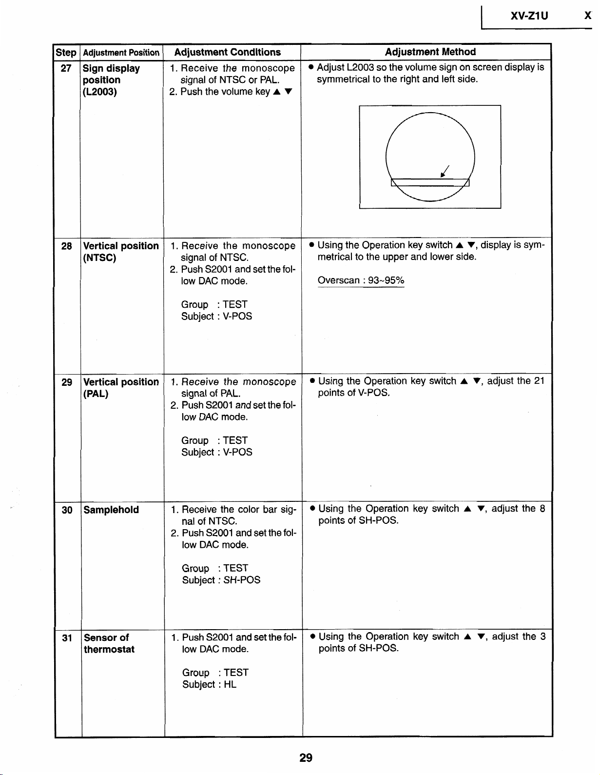
27 Sign display
1. Receive
the
monoscope
l
Adjust L2003
so
the volume sign on screen
display is
position
signal of NTSC or PAL.
symmetrical
to the
right and
left side.
(L2003)
2.
Push the
volume key A
v
28
Vertical
position
1.
Receive the monoscope
l
Using
the
Operation
key switch
A v, display is
sym-
(NTSC)
signal of NTSC.
metrical to the upper
and
lower
side.
2. Push S2001 and set
the fol-
low DAC mode.
Overscan : 93-95%
Group
: TEST
Subject :
V-POS
29
Vertical position
1.
Receive the monoscope
l
Using the Operation key switch A v, adjust the 21
(PAL)
signal of PAL.
points of V-POS.
2. Push S2001 and set the fol-
low DAC mode.
Group :
TEST
Subject : V-POS
30
Samplehold
1, Receive the color bar sig-
l
Using the Operation key switch A v, adjust the
8
nal of NTSC.
points of SH-POS.
2. Push S2001 and set the fol-
low DAC mode.
Group : TEST
Subject : SH-POS
31 Sensor of
thermostat
1. Push S2001 and set the fol-
l
Using the Operation key switch A V, adjust the 3
low DAC mode.
points of SH-POS.
Group : TEST
Subject : HL
Loading...