


24" FLUSH MOUNT DEFLECTOR VENT: SKMD24F0AS
INSTALLATION INSTRUCTIONS
IMPORTANT NOTES TO THE INSTALLER
ÊU Read all of the Installation Manual that is included with
WKH 0LFURZDYH 'UDZHU EHIRUH LQVWDOOLQJ LQ WKH ÁXVK PRXQW FRQÀJXUDWLRQ
ÊU Observe all governing codes, ordinances, and safety instructions.
ÊUÊÊ%H VXUH WR OHDYH WKHVH LQVWUXFWLRQV ZLWK WKH FRQVXPHU
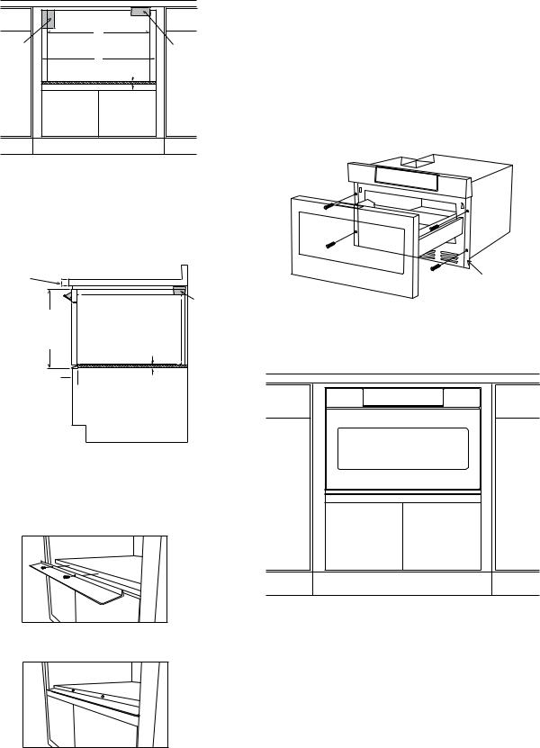
1. Prepare cabinet opening as shown in Figures 1, 2A, 2B, 2C.
Parts includes:
Qty. |
Part number |
PREF-B019MRP0 Flush Mount
1 'HÁHFWRU 9HQW
2
LX-CZB055MRE0
Mounting screws
|
|
|
|
A |
$PP |
|
|
B |
|
|
C |
B. Suggested electrical outlet location |
|
|
|
|
|
|||
|
|
|
|
C. Anti-Tip block |
||
|
|
|
|
E |
||
|
|
|
D |
' PP |
||
|
|
|
|
|||
|
|
|
|
|
( PP |
|
|
G |
F |
|
|
) PP |
|
|
|
|
H |
|||
|
|
|
|
* PP PLQLPXP |
||
|
|
|
|
Note: the face of the shelf must |
||
I |
K |
|
|
|
PP PD[LPXP |
|
|
|
sit 1 3/4" (44.45 mm) back from |
|
|||
|
L |
J |
M |
the face of the cabinet. |
+ PP WR ERWWRP RI |
|
|
|
|
|
|
Anti-Tip block |
|
|
|
|
|
N |
|
|
|
|
|
|
, |
PP |
|
|
|
|
|
shelf face O |
||
|
|
|
|
|
- |
PP PLQLPXP GHSWK |
|
|
|
|
cabinet face |
. PP |
|
|
|
|
|
|
/ PP |
|
|
|
|
|
|
0 PP RSHQLQJ |
|
|
|
|
|
|
1 )ORRU PXVW VXSSRUW OE NJ |
|
|
|
|
|
|
2 PP |
|
Figure 1
Anti-Tip block
A |
Mounting cleat |
Drawer face |
B |
C |
Cabinet |
face |
C L
Top view Note: the mounting surface of the finished cleat must sit 1 1/16" (26.97 mm) back from the face of the cabinet [pushing the face of the drawer out 1/4" (6.35 mm)].
$PP PRXQWLQJ FOHDW RSHQLQJ ZLGWK % PP
& PP
Figure 2A
E 1
TINSEB541MRR2
|
No oven |
Suggested electrical |
A |
|
|
outlet location |
Anti-Tip block |
|
B |
|
C |
Figure 2B |
Front view |
$PP PRXQWLQJ FOHDW RSHQLQJ ZLGWK % PP PLQLPXP
PP PD[LPXP
ÁXVK RSHQLQJ ZLGWK
& PP VKHOI
Move oven location |
|
downward for extended |
|
countertops for better |
|
viewing angle. |
Anti-Tip |
16 7/8" |
block |
|
|
(428.62 mm) |
|
flush opening |
3/4" (19.05 mm) |
height |
|
|
shelf |
Front face of cabinet 
 1 3/4" (44.45 mm) front face of shelf
Figure 2C
Side view
,QVWDOO GHÁHFWRU DV VKRZQ LQ )LJXUH $
Shelf detail showing the deflector vent during installation.
Position deflector vent and mark holes. Pre drill using a 1/16" (1.57 mm) bit before mounting.
Figure 3A
Shelf detail showing the deflector vent installed.
Figure 3B
3.Place the drawer adjacent to the wall or cabinet opening. Plug the power supply cord into the electrical outlet.
4.Carefully guide the drawer into the prepared opening. Avoid contact with the sides of the cutout opening and also pinching the cord between the oven and the wall.
6OLGH WKH GUDZHU DOO WKH ZD\ EDFN XQWLO WKH PRXQWLQJ ÁDQJHV WRXFK WKH FOHDWV PRXQWHG LQ WKH FDELQHW RSHQLQJ
2SHQWKHGUDZHU 8VLQJWKH KROHVRQWKHGUDZHUDVDWHPSODWH SUH GULOO WKH FDELQHW XVLQJ D µ PP ELW 6HH )LJXUH
Mounting flange
Figure 4
7. Secure the drawer with the 4 screws supplied.
E 2
 Loading...