


SJ59MSL1-69WH1
1
SJ-59M
SJ-69M
SERVICE MANUAL
S9334SE68DPU1
SHARP CORPORATION
TABLE OF CONTENTS
page
CAUTIONS AND INFORMATIONS ..................................................................................................................2
SPECIFICATIONS ............................................................................................................................................3
DESIGNATION OF VARIOUS PARTS .............................................................................................................5
LIST OF ELECTRICAL PARTS ........................................................................................................................6
DIMENSIONS ...................................................................................................................................................6
WIRING DIAGRAM...........................................................................................................................................8
FUNCTIONS ...................................................................................................................................................10
ASSEMBLING PROCEDURES OF MAIN PARTS AND CAUTIONS .............................................................13
COOLING UNIT ..............................................................................................................................................21
REPLACEMENT PARTS LIST .......................................................................................................................23
Refrigerant; HFC-134a
Refer to "HFC-134a COOLING UNIT" Service Manual for handling this refrigerant.
DESTINATION ......................... 1
In the interests of user-safety (Required by safety regulations in some
countries) the set should be restored to its original condition and only
parts identical to those specified should be used.
REFRIGERATOR-FREEZER
MODELS
SJ-59M
-SL1/WH1
SJ-69M
-SL1/WH1
2
SJ-59M
SJ-69M
Some household cleaning chemicals may affect the internal
food liner and plastic parts resulting in splitting or cracks
occurring.
When cleaning all plastic parts inside this refrigerator, only
use diluted dishwashing liquid(soapy water). Make sure that
all plastic parts are thoroughly rinsed with water after cleaning.
CAUTIONS AND INFORMATIONS
1. Some foods freezed in the refrigerator compartment.
2. Some plastic parts were cracked or splitted.
Cracking or crunching sound;
Sound produced by expansion and contraction of inner walls and internal parts during cooling.
Squeaking sound;
Sound produced by expansion and contraction of internal parts.
Sound of flowing fluid (gurgling sound, fizzing sound);
Sound of refrigerant flowing in pipes (sound may become louder from time to time).
3. IT IS NORMAL for the refrigerator to produce the following sounds.
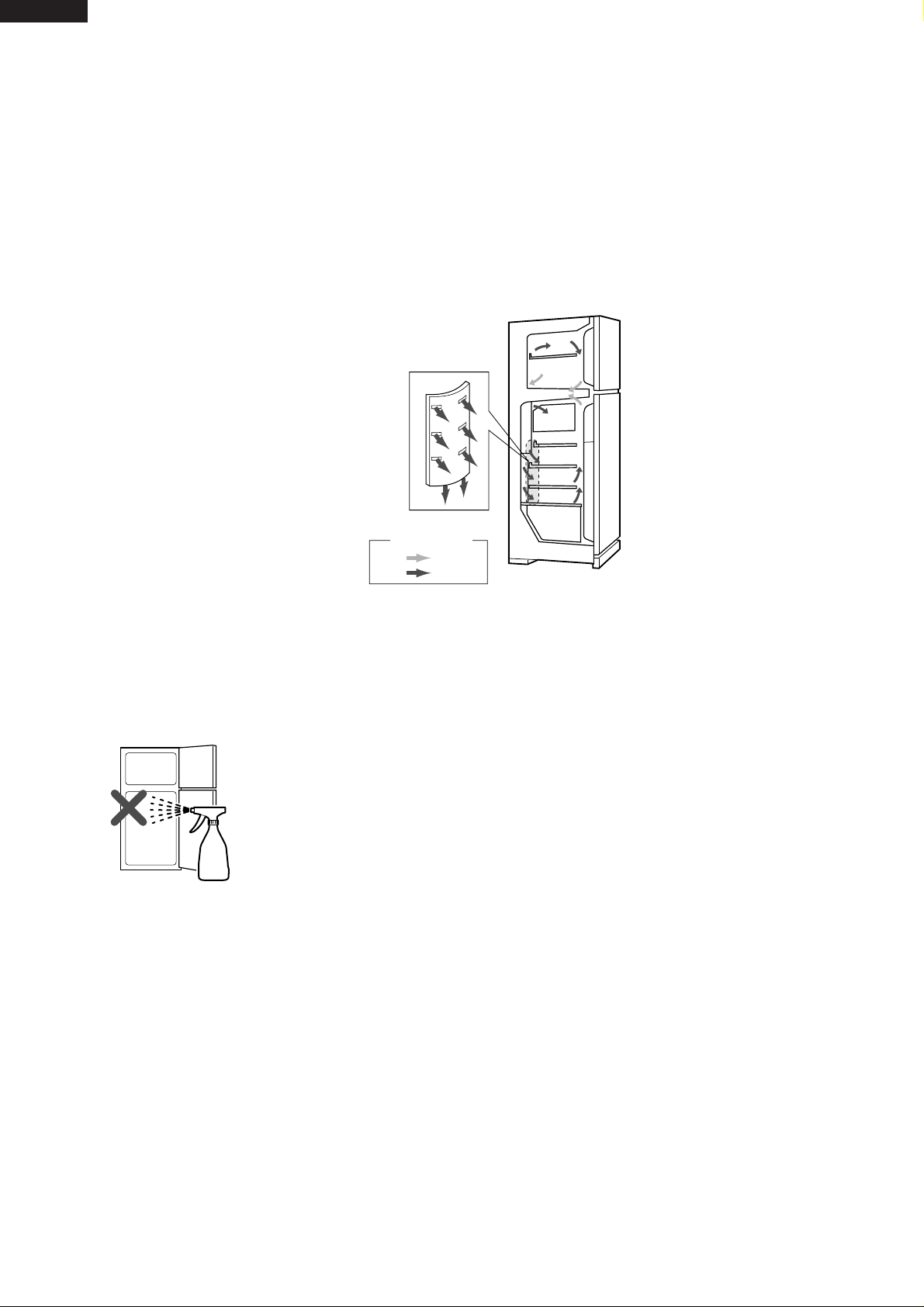
Do not place food directly in front of
cold air outlet.
This may lead to the food freezing.
IN
OUT
cold air flow
In case of following troubles, the cause is not related with the failure of refrigerator.
Please mention the correct way to the customer for the use of refrigerator when the repairing.
3
SJ-59M
SJ-69M
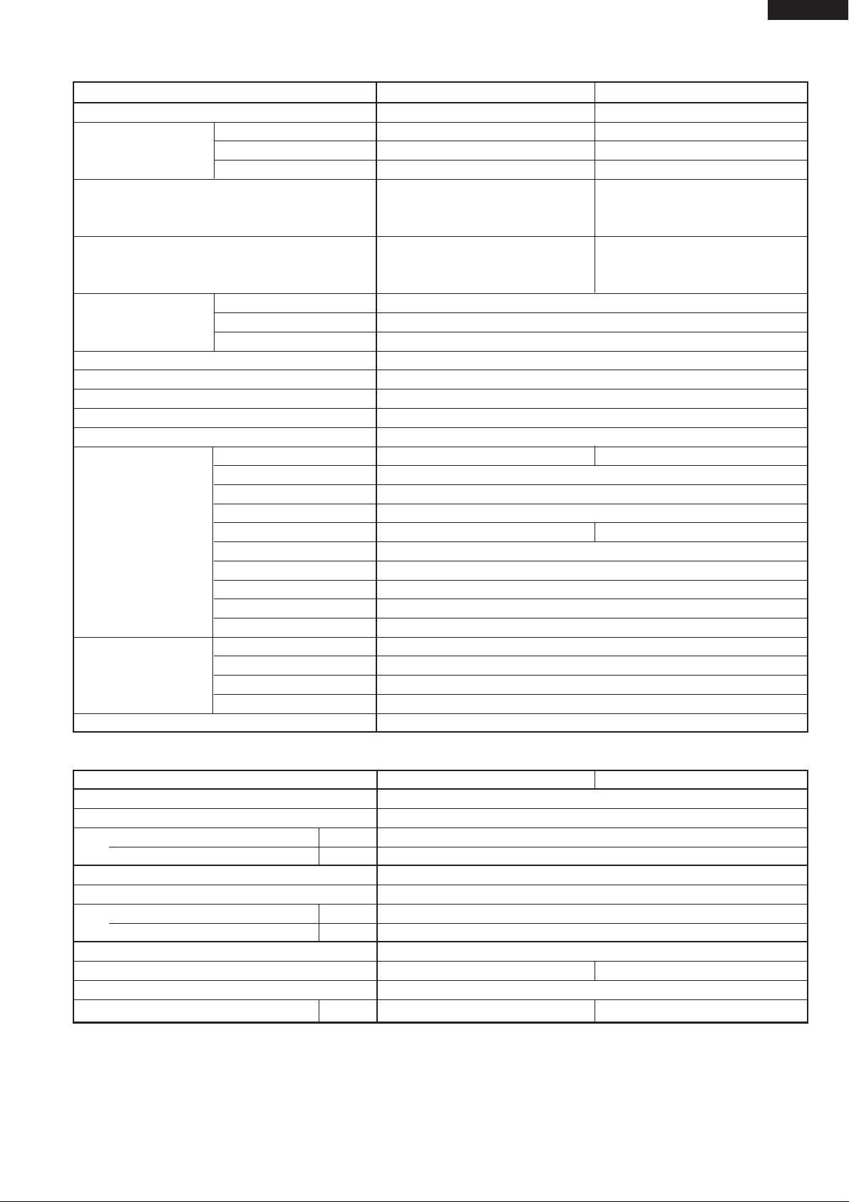
SPECIFICATIONS
Items SJ-59M SJ-69M
Type 2-Door 2-Door
Outer dimensions Height 1620mm(63.8") 1820mm(71.6")
Width 760mm(29.9") 760mm(29.9")
Depth 740mm(29.1") 740mm(29.1")
Rated storage volume 492 liter (17.4 cu.ft) 577 liter (20.4 cu.ft)
(Rated volume) F: 151 liter (5.3 cu.ft) F: 151 liter (5.3 cu.ft)
R: 341 liter(12.1 cu.ft) R: 426 liter
(15.1 cu.ft)
Gross volume 526 liter (18.6 cu.ft) 606 liter (21.4 cu.ft)
F: 177 liter (6.3 cu.ft) F: 177 liter (6.3 cu.ft)
R: 349 liter(12.3 cu.ft) R: 429 liter
(15.1 cu.ft)
Defrosting System Heater system
Start Automatic
Finish Automatic
Temperature control Automatic (Adjustable)
No-frost freezer Yes
Interior lamp 2
Caster 4
Evaporating pan 1
Refrigerator R glass shelf ass'y 2 3
Compartment V glass shelf ass'y 1
Vegetable case 1
V parting plate 1
R door pocket 1 2
Egg tray 2
Bottle pocket 2
Utility case pocket 1
Fresh case 1
Tube stand 2
Freezer Freezer shelf ass'y 1
Compartment Ice cube maker Twin ice cube maker
Ice storage box 1
F door pocket 2
Deodorizing unit 2 (Honeycomb type)
RATING
Items SJ-59M SJ-69M
Rated voltage 110V~
Rated frequency 50Hz
Rated current (A) 2.9
Rated input of heating systems (W) 140
Rated voltage 110-120V~
Rated frequency 60Hz
Rated current (A) 2.9-3.0
Rated input of heating systems (W) 140-165
Climate class ST
Refrigerant (Charging quantity)
[Non-flammable]
HFC-134a(120g) HFC-134a(130g)
Insulation blowing gas
[Flammable]
Cyclo pentane (HC)
Net Weight (kg) 83 90
4
SJ-59M
SJ-69M
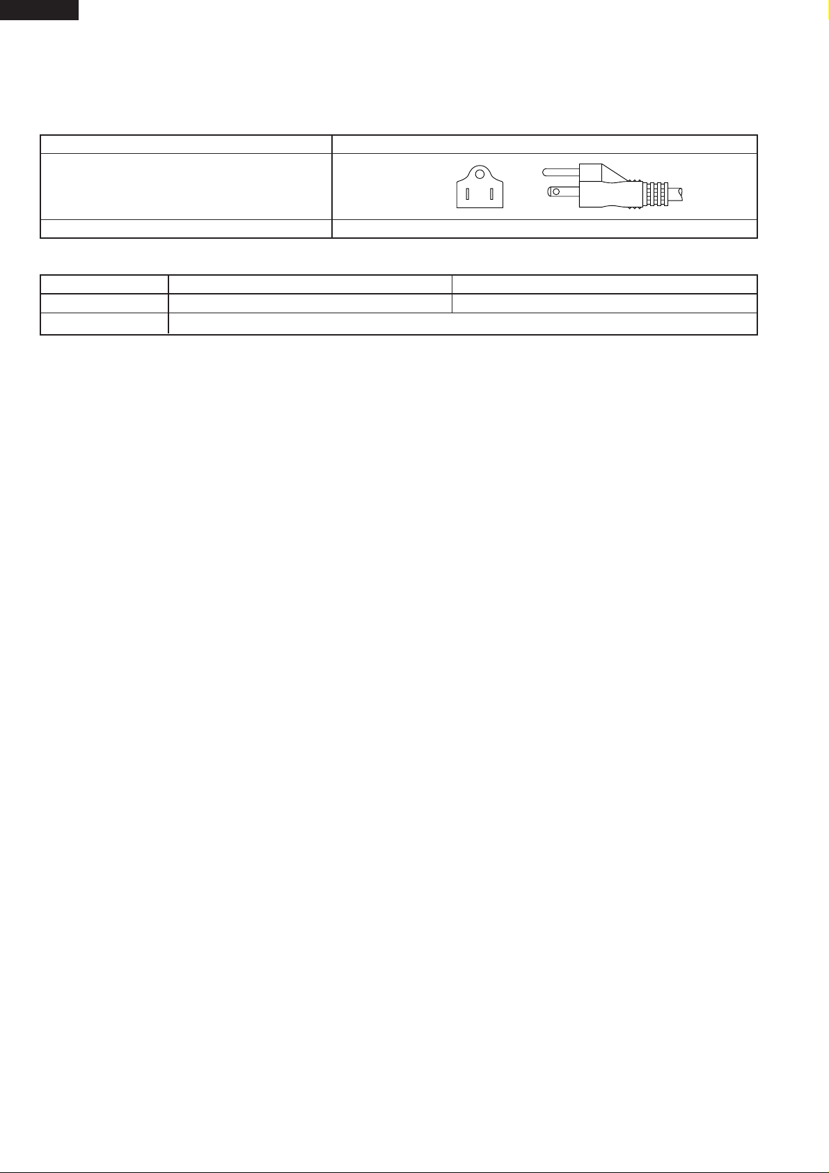
PLUG TYPE
Plug cord 3 pin
Plug type A-2(UL type)
Destination mark 1
COLOR
Items -SL1 -WH1
Outside color Silver White
Inside color White
5
SJ-59M
SJ-69M
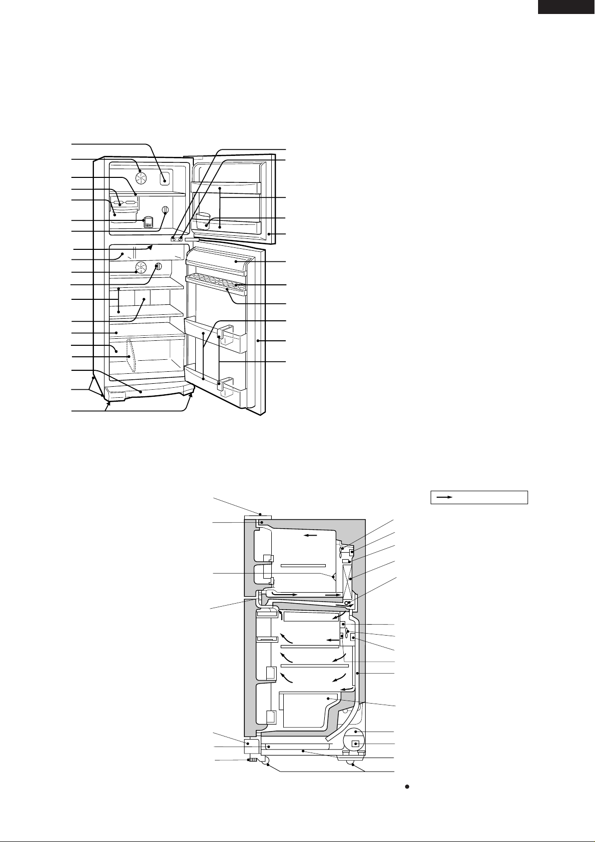
DESIGNATION OF VARIOUS PAR TS
Figure D-1. External Description
Figure D-2. Constructions
This figure shows SJ-59M
The names in parenthesis" [ ]" are the denominations
used in the REPLACEMENT PARTS LIST.
1. Freezer light [Lamp]
2. Freezer fan
3. Freezer shelf [F shelf ass’y]
4. Ice cube maker
5. Ice cube box [Ice storage box]
6. Deodorizing unit
7. Freezer temp. control knob
8. Fresh case [Chilled case]
9. Refrigerator fan
10. Refrigerator temp. control knob
11. Refrigerator shelf [R glass shelf ass’y]
(59 type; 2 shelves, 69 type; 3 shelves)
12. Refrigerator light [Lamp]
13. Shelf [V glass shelf ass’y]
14. Vegetable crispe r[Vegetable case]
15. Separator plate [V parting plate]
16. Evaporating pan & cover
17. Casters
18. Adjustable feet [Adjustable leg ass’y]
19. Fan & light switch for freezer
20. Fan & light switch for refrigerator
21. Freezer pocket [F door pocket]
22. Water supply cup [Water cup]
23. Magnetic door seal [Door packing]
24. Utility case [Utility case pocket]
25. Egg holder [Egg tray]
26. Free pocket[R door pocket]
(59 type; 1 pocket, 69 type; 2 pockets)
27. Bottle pocket
28. Bottle guard [Tube stand]
1
19
20
21
22
23
24
25
26
27
28
3
2
4
5
7
6
6
8
9
10
11
12
13
14
17
18
15
16
23
Upper hinge cover
Hot pipe
Freezer temp. control knob
Hot pipe
Evaporating pan cover
Evaporating pan
Adjustable leg ass’y
Fan motor
Freezer fan
Defrost thermostat
Evaporator
Defrost heater
Damper thermostat
Refrigerator temp. control knob
Drain pipe
Vegetable case
Compressor
Starting relay, Overload relay(Protector)
Caster
Sub condenser
Freezer
compartment
Refrigerator
compartment
Mark: Cold air flow
Timer,R-fan thermo ass’y
Refrigerator fan
6
SJ-59M
SJ-69M
LIST OF ELECTRICAL PARTS
ITEMS TYPE NAME RATING SPECIFICATIONS
Thermostat MM1-8123 125V 6A (At normal notch)
250V 3A ON/OFF : -19/-24˚C
Defrost thermostat S101 250V 8A Open/Close : 10/1˚C
Thermo. fuse SF70E 250V 10A Working temp. : 70˚C
F-fan motor 3R00171 110-120V 60Hz Working with ø100 fan
R-fan motor 3R00122B 100V 50/60Hz Working with ø80 fan
110V 60Hz
(R-fan fuse) 123 250V 2A Cut OFF 130˚C
Defrost heater MM6-4286 110-120V 88.2Ω 150W at 115V
Door switch DSD-5 250V 0.25A 4 terminals push-button type
Damper thermostat MM1-6176 — Open/Close : 2/-3˚C
Defrost timer TMDFX04FB2 110-127V Integration type
50/60Hz Cycle time : 12h / 10h (50/60Hz)
Delay time : 4.8m / 4.0m (50/60Hz)
Lamp socket (F/R) — 250V 1A E-12(Hard plastic body type)
F-lamp — 130V 10W E-12
R-lamp — 130V 15W E-12
R-fan thermo.
R-fan thermo.
S101 250V 8A Open/ Close : 7/15˚C
ass'y
R-fan thermo.heater
RSS2 350V, 2W, 10kΩ 1.1W at 230V
Compressor FGI85HAK 115V/60Hz Cooling capacity : 209kcal/h(60Hz)
Main coil : 1.78 Ω
Aux. coil : 6.8 Ω
(at 25˚C)
Starting relay PTH7M4R7MC1 — 4.7 Ω 20% (at 25˚C) 180V
Overload relay(Protector) 4TM771RFBZZ — Open/ Close : 130˚C / 61˚C
Common
Main coil
Aux. coil
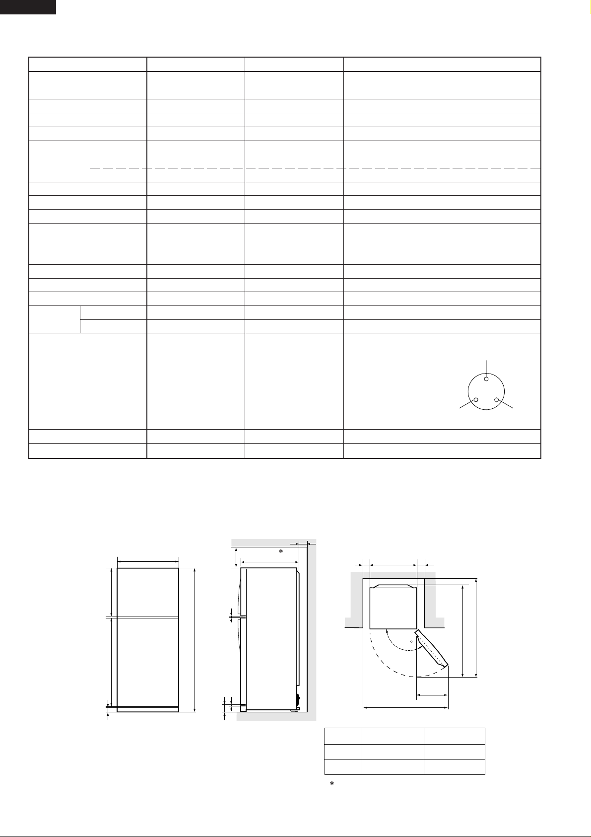
DIMENSIONS
OUTER DIMENSIONS AND CLEARANCE
Fig. E-1
760
760
520
1340
1620
979
1820
1179
740
90
more than
60
more than
60
more than
60
more than
553
9.512
72.5
60.5
A
B
1420
1480
Include the panel/badge. Not include the handle.
A
SJ-59M
SJ-69M
B
1
1
135
( Unit : mm)
–
+
7
SJ-59M
SJ-69M
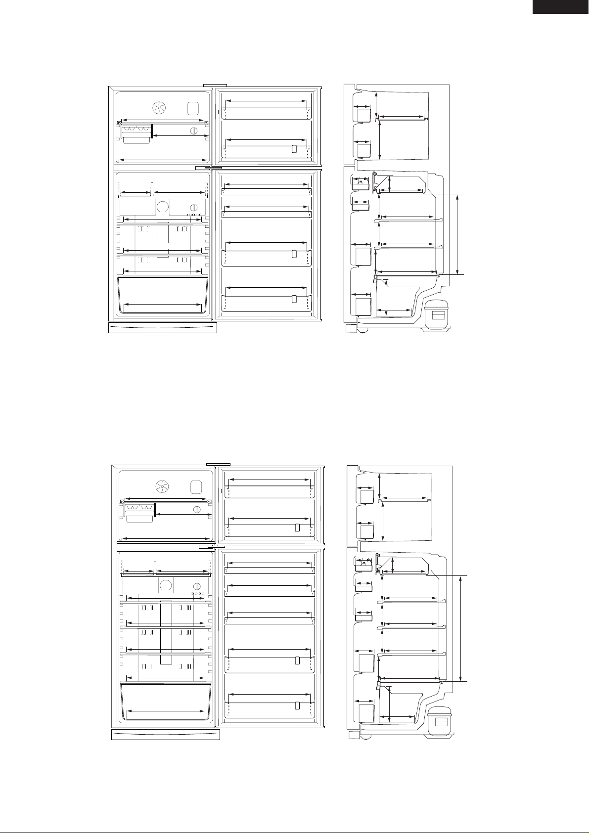
INNER DIMENSIONS
Fig. E-2 (SJ-59M)
Fig. E-3 (SJ-69M)
294
90
90
587
603
450
630
355177
587
615
615
607
607
174
264
125
180
466
135
121
242
110
285
310
310
335
227
133
133
110
615
615
615
600
The dimensions between shelves can be changed
by setting the shelves on the other rails.
( Unit : mm)
The dimensions between shelves can be changed
by setting the shelves on the other rails.
294
587
603
450
630
355177
587
615
615
607
607
174
264
125
180135135
171
666
242
110
110
285
310
310
310
335
227
133
133
110
90
90
615
615
615
600
615
615
( Unit : mm)
8
SJ-59M
SJ-69M
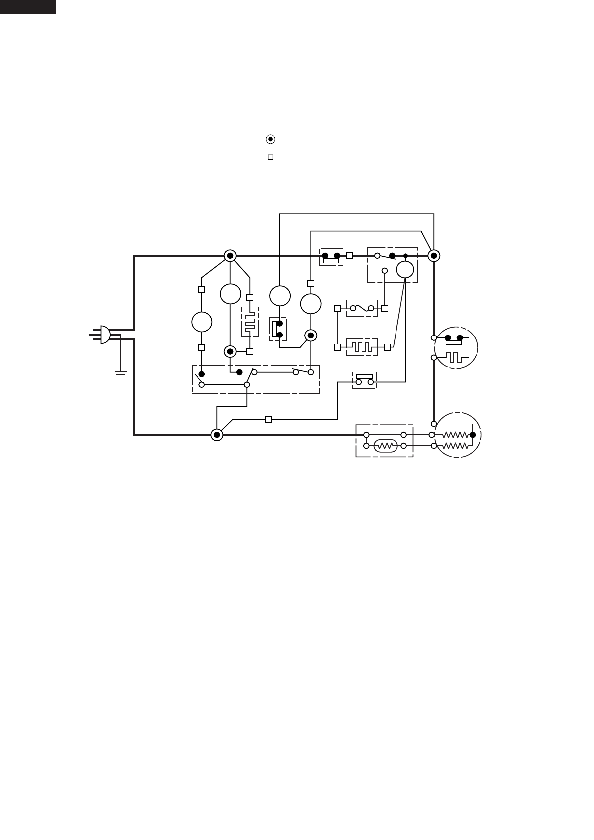
WIRING DIAGRAM
Be sure to replace the electrical parts with specified ones for maintaining the safety and performance of the set.
Figure W-1. Wiring Diagram
Figure W-2. Wiring Diagram (SJ-59M,69M)
CONNECTED IN TERMINAL BOX
CONNECTOR
G
BR
OR
Y
R
P
B
BK
SB
G-Y
W
: GRAY
: BROWN (Live)
: ORANGE
: YELLOW
: RED
: PINK
: BLUE (Neutral)
: BLACK
: SKY-BLUE
: GREEN-YELLOW (Earth)
: WHITE
(Br)
(G)
(B)
3PIN
PLUG/
CORD
C
M
A
FM
FM
L
L
F
DEF. TIMER
THERMOSTAT
DEFROST HEATER
DEFROST THERMO
COMPRESSOR
PROTECTOR
DOOR SWITCH
THERMO.
FUSE
R
TM
R-FM
HEATER
STARTING RELAY
R-FAN
THERMO
(G—Y)
F-LAMP
R-
LAMP
9
SJ-59M
SJ-69M
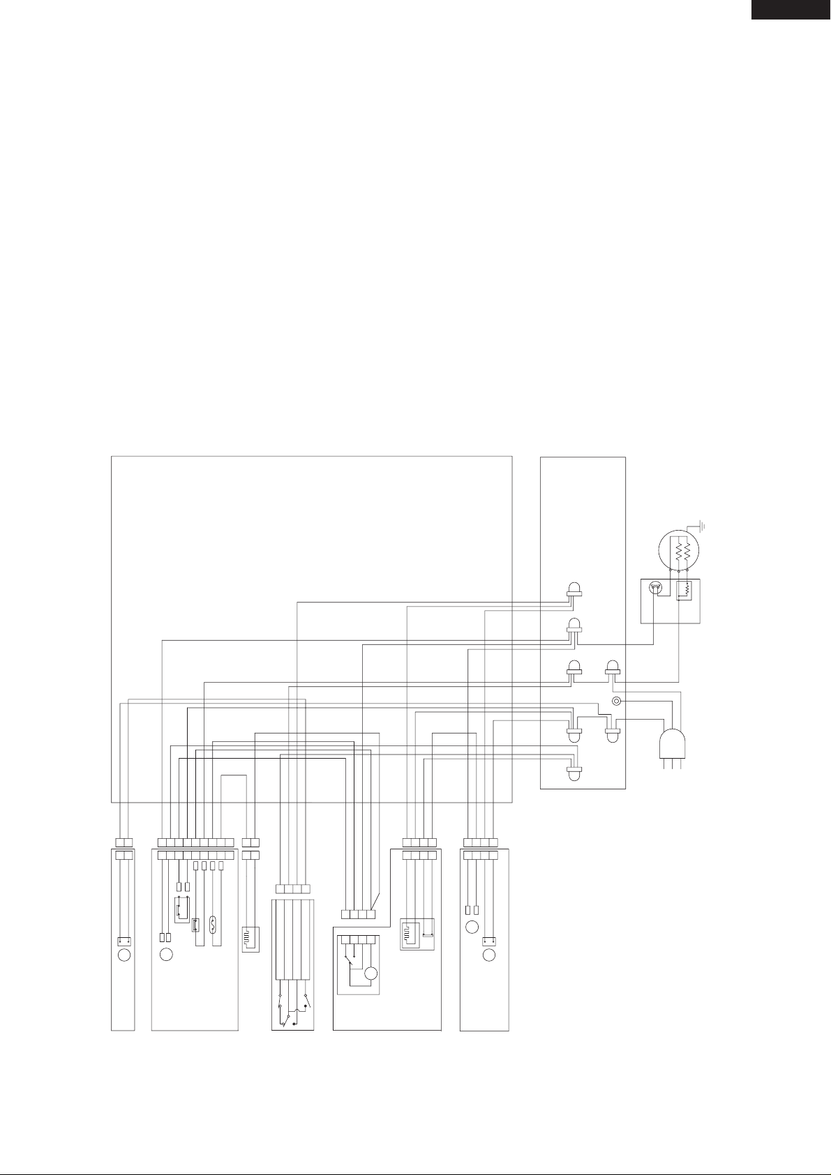
Figure W-2. Electric Accessories Layout
F LAMP BOX ASS’Y
LAMP(10W)
L
LAMP SOCKET
CABINET ASS’Y
E. V. COVER ASS’Y
LEAD EV-COVER ASS’Y
FAN MOTOR
F-THERMOSTAT
DEF. THERMO. ASS’Y
FUSE ASS’Y
FM
DEF. HEATER ASS’Y
DOOR SWITCH
3 (PUSH CLOSE)
1 (NEUTRAL)
4 (PUSH OPEN)
2 (PUSH OPEN)
TM
FM
R CONTROL COV. ASS’Y
DEFROST TIMER
(R-FAN
THERMO. HEATER)
R FAN THERMO.
R LAMP BOX ASS’Y
L
R-FAN MOTOR
R-LAMP (15W)
LAMP SOCKET
BROWN 1
BROWN 2
BLUE 1
GRAY 1
SKY-BLUE
SOURCE CORD
TERMINAL BLOCK
COMPRESSOR
STARTING RELAY
PROTECTOR
3
1
4
2
1
2
1
2
1
2
1
2
1
2
3
4
1
2
3
4
1
2
3
4
1
2
3
4
1
2
3
4
1
2
3
4
1
2
3
4
5
7
6
8
9
1
2
3
4
5
7
6
8
9
GY-1
OR-2
BL-2
SB-1
SB-2
SB-3
BR-3
BR-5
OR-3
OR-2
(OR-4)
(W-2)
OR-1
R-1
BR-2
Y-1
(R-1)
(BK-1)
GY-2
(Y-1)
(Y-2)
BL-1
BK-1
W-1
BR-1
W-2
(W-1)
Y-2
C
M
A
GY-3
BLUE 2
ORANGE
EARTH
TERMINAL BOX
G
BR
OR
Y
R
P
B
BK
SB
G-Y
W
: GRAY
: BROWN (Live)
: ORANGE
: YELLOW
: RED
: PINK
: BLUE (Neutral)
: BLACK
: SKY-BLUE
: GREEN-YELLOW (Earth)
: WHITE
 Loading...