


 Loading...
Sharp TQ-GX30U, TQ-GX30K, TQ-GX30C, TQ-GX30F, TQ-GX30L Service Manual
...CONFIDENTIAL |
GX30 |
SERVICE MANUAL
No. S5409TQGX30/B
DIGITAL MOBILE PHONE
MODEL GX30
(INTERNAL MODEL NAME: TQ-GX30E/G/R/T/S/H/EP/PP/W/B/D/A/Z/Q/L/F/C/K/U)
|
|
|
E : For U.K. |
G : For Germany |
|
|
|
R : For Ireland |
T : For Italy |
|
|
|
S : For Spain |
H : For Netherlands |
|
|
|
||
|
|
|
||
|
|
|
EP: For U.K. (Prepaid) |
PP: For Portugal (Prepaid) |
|
|
|
||
|
|
|
W : For Sweden |
B : For Hungary |
|
|
|
||
|
|
|
D : For Greece |
A : For Australia |
|
|
|
Z : For New Zealand |
Q : For Egypt |
|
|
|
L : For Malta |
F : For France |
|
|
|
C : For Switzerland |
K : For Austria |
|
|
|
U : For Belgium |
|
•In the interests of user-safety the set should be restored to its original condition and only parts identical to those specified should be used.
•Caution
Risk of explosion if battery is replaced by an incorrect type, dispose of used batteries according to the instruction.
CONTENTS
SERVICING CONCERNS |
|
|
CHAPTER 1. GENERAL DESCRIPTION |
|
|
[1] |
Specifications................................................ |
1-1 |
[2] |
Names of parts.............................................. |
1-2 |
[3] |
Operation manual ......................................... |
1-3 |
CHAPTER 2. ADJUSTMENTS, |
|
|
|
PERFORMANCE CHECK, AND |
|
|
FIRMWARE UPGRADE |
|
[1] SHARP Program Support Tool (SPST)......... |
2-1 |
|
[2] |
Test points................................................... |
2-44 |
[3] |
Troubleshooting .......................................... |
2-48 |
CHAPTER 3. DISASSEMBLY AND REASSEMBLY |
||
[1] |
Servicing Concerns....................................... |
3-1 |
[2] |
Disassembly and reassembly ....................... |
3-4 |
CHAPTER 4. DIAGRAMS |
|
|
[1] |
Block diagram................................................ |
4-1 |
CHAPTER 5. SCHEMATIC DIAGRAM AND |
|
|
|
WIRING SIDE OF P.W.BOARD |
|
[1] Notes on schematic diagram......................... |
5-1 |
|
[2] Types of transistor and LED .......................... |
5-1 |
|
[3] |
Waveforms of circuit ...................................... |
5-2 |
[4]Schematic diagram/
|
Wiring side of P.W.Board |
............................. 5-5 |
CHAPTER 6. OTHERS |
|
|
[1] Function table of IC ....................................... |
6-1 |
|
[2] |
Function table of Camera ............................ |
6-27 |
[3] |
Function table of Display ............................. |
6-28 |
Parts Guide
Parts marked with "  " are important for maintaining the safety of the set. Be sure to replace these parts with specified ones for maintaining the safety and performance of the set.
|
|
SHARP CORPORATION |
This document has been published to be used |
for after sales service only. |
|
|
The contents are subject to change without notice. |
GX30 |
CONFIDENTIAL |
SERVICING CONCERNS
1.When requested, back-up user’s handset data using SPST (SHARP Program Support Tool). Otherwise, before servicing, warn the user that data in the memory may be lost during repairs.
2.Upgrade the firmware to the latest version using SPST before returning the handset to the customer.
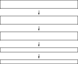
3.After repairs, inspect the handset according to the following flowchart.
Repairs are completed.
(Fixed parts have been checked for proper operation.)
Check IMEI NO./Operator code (Destination)/
Firmware version by Identity function of SPST.
Inspect each device using performance check adjustment function of SPST.
Carry out RF performance check with SPST.
All completed.
4.When storing or transporting a PWB, put it into a conductive bag or wrap it in aluminum foil. (C-MOS IC may be damaged by electrostatic charges.)
5.Do not leave fingerprints, etc. on ornamental parts including a cabinet, especially clear windows for main and sub displays. Wear fingerstalls to avoid this.
Also, ensure not to leave fingerprints on the surface of main and external display panels.
6.To prevent oxidation which causes connection problems, do not touch any terminals on the electric board, microphone, vibrator, earpiece and speaker.
When handling these parts, wear fingerstalls. Should you touch these parts, clean them with a soft dry cloth.
Always wear fingerstalls when handling a shield case on the electric board. Otherwise oxidation may occur causing handset performance deterioration.
7.The FPC is a precision device. Handle it carefully to prevent any damages.
8.Do not expose the moisture sensor to liquids.
If the sheet gets wet, red ink runs. In this case, replace the sheet with a new one. Be careful about your perspiration.
9.Before you disassemble or reassemble handset, make sure to remove the Li-Ion battery.
10.Be sufficiently careful with static electricity of integrated circuits and other circuits. Wear static electricity prevention bands while servicing.
i
CONFIDENTIAL |
GX30 |
CHAPTER 1. GENERAL DESCRIPTION
FOR A COMPLETE DESCRIPTION OF THE OPERATION OF THIS UNIT, PLEASE
REFER TO THE OPERATION MANUAL.
[1] Specifications
General: |
Quad - band (GSM 850 MHz/GSM 900 MHz/ |
|
DCS 1800 MHz/PCS 1900MHz) |
|
GPRS-enabled |
|
WAP, MMS, SMS |
Dimensions |
|
(folded, exclud- |
|
ing the aerial) |
|
(H x W x D): |
95 x 49 x 26 mm |
Weight: |
110 g |
Battery operating |
|
temperature: |
0°C - 40°C |
Main display: |
Display dimensions: 240 x 320 pixels |
|
LCD display: CGS 262,144 colours with back- |
|
light |
|
LCD back light: LED back light white colour LEDs |
External display: |
Display dimensions: 64 x 96 pixels |
|
LCD display: STN 65,536 colours LCD with back |
|
light |
Camera: |
CCD 1M pixels built-in camera |
|
Zoom: Wide and zoom mode |
|
[Supported 20 (when image size is |
|
160 x 120 pixels) x zoom] |
|
Lens: F2.8, f = 3.7 mm |
Powered by JBlendTM Copyright 19972003 Aplix Corporation. All rights reserved. JBlend and all JBlend-based trademarks and logos are trademarks or registered trademarks of Aplix Corporation in Japan and other countries.
Powered by Mascot Capsule R /Micro3D EditionTM
Mascot CapsuleR is a registered trademark of HI Corporation
C 2002-2003 HI Corporation. All Rights Reserved.
Licensed by Inter Digital Technology Corporation under one or more of the following United States Patents and/or their domestic or foreign counterparts and other patents pending, including U.S. Patents: 4,675,863: 4,779,262: 4,785,450 & 4,811,420.
Licensed under U.S. Patent 4,558,302 and foreign counterparts.
Sound: |
40-polyphonic ring melodies |
Mobile light: |
7 colours |
External DC |
|
supply voltage: |
5.2 V |
Battery: |
3.7 V, 780 mAh, Li-Ion |
Standby time: |
100 ~ 250 hours |
Talk time: |
160 ~ 240 min. |
Others: |
Side key |
|
Infrared port 1.2 L/P (maximum distance 20 cm) |
|
Connector for AC charger and data cable |
|
Standard hands free connector (ø2.5) |
Battery running time depends on the battery and SIM card as well as the network conditions and usage
Specifications for this model are subject to change without prior notice.
T9 Text Input is licensed under one or more of the following: U.S. Pat. Nos. 5,818,437, 5,953,541, 5,187,480, 5,945,928, and 6,011,554; Australian Pat. No. 727539; Canadian Pat. No. 1,331,057;United Kingdom Pat. No. 2238414B; Hong Kong Standard Pat. No. HK0940329; Republic of Singapore Pat. No. 51383; Euro. Pat. No. 0 842 463 (96927260.8) DE/DK, FI, FR, IT, NL,PT.ES,SE,GB; Republic of Korea Pat. Nos. KR201211B1 and KR226206B1; and additional patents are pending worldwide.
SD logo  is a trademark.
Bluetooth is a trademark of the Bluetooth SIG, Inc.
The Bluetooth word mark and logos are owned by the Bluetooth SIG, Inc. and any use of such marks by Sharp is under license. Other trademarks and trade names are those of their respective owners.
CP8 PATENT
1 – 1
GX30
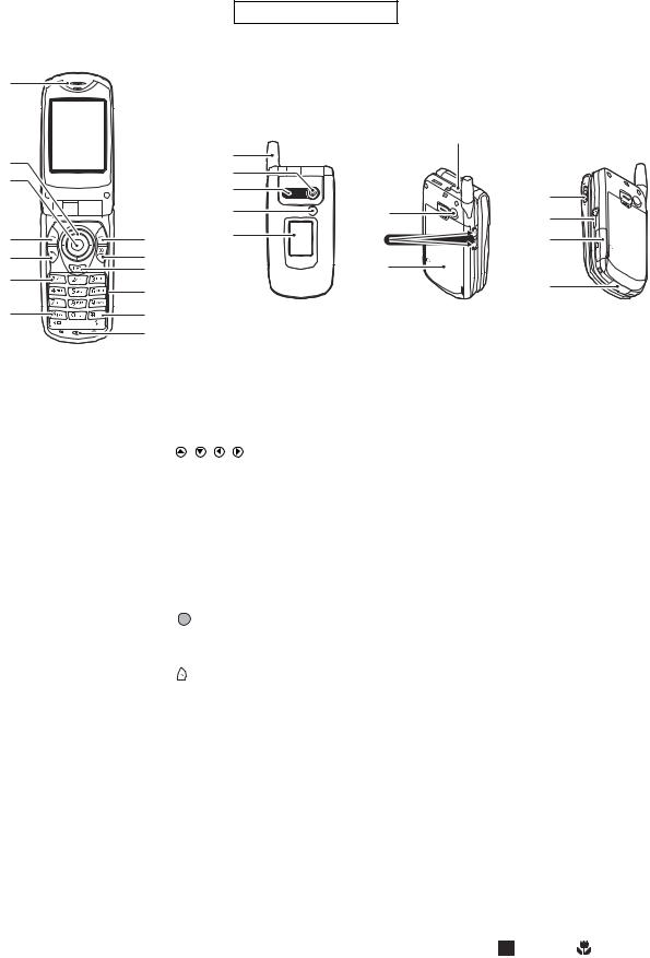
[2] Names of parts
1
 8
8
2
3
4 |
9 |
5 |
10 |
|
11 |
6 |
|
|
12 |
7 |
13 |
|
14 |
CONFIDENTIAL
15 |
16 |
17 |
18 |
19 |
|
20 |
|
24 |
21 |
25 |
|
|
22 |
26 |
23 |
|
|
27 |
1.Earpiece
2.Navigation Keys (Arrow Keys):
|
|
Moves cursor to select |
|
|
menu items, etc. |
|
|
, , , in this |
|
|
manual indicate these keys. |
|
Up/Down arrow keys: |
Displays Contacts List |
|
|
entries in stand-by mode. |
|
Left arrow key: |
Displays list of |
|
|
Applications in stand-by |
|
|
mode. |
|
Right arrow key: |
Displays Pictures screen in |
|
|
stand-by mode. |
3. |
Centre Key: |
Displays Main menu in |
|
|
stand-by mode and |
|
|
executes functions. |
|
|
in this manual indicates |
|
|
this key. |
4. |
Left Soft Key: |
Executes the function at the |
|
|
bottom left of the screen. |
|
|
in this manual indicates |
|
|
this key. |
5. Send Key: |
Makes or accepts calls, |
|
|
|
views the call in stand-by |
|
|
mode. |
6. Voice Mail Key: |
Press and hold this key to |
|
|
|
connect to the Voice mail |
|
|
centre automatically. |
|
|
(Depends on the SIM card.) |
7. |
* /Shift Key, |
|
|
Viewfinder Switch Key: |
|
|
|
Switches character case |
|
|
among four modes: Abc, |
|
|
ABC, 123 and abc. |
Switches viewfinders between main display and external display in digital camera/video camera mode.
8.Main Display
9.Right Soft Key: Executes the function at the
bottom right of the screen.  in this manual indicates this key.
Used to access “Vodafone live!” by opening the browser in stand-by mode.
10.End/Power Key: Ends a call, turns power on/ off.
11.Camera Key: |
Starts the digital camera in |
|
stand-by mode. |
12.Keypad |
|
13.#/Flash light Key: |
Switches symbol screens. |
|
Press and hold this key to |
|
shift text input method |
|
between multi-tap and T9 |
|
mode. |
|
Turns the flash/auxiliary |
|
light on or off in digital |
|
camera/video camera |
|
mode. |
14.Microphone |
|
15.Aerial |
|
16.Camera |
|
17.Speaker |
|
18.Mobile Light: |
Used as a flash or an |
|
auxiliary light in digital |
|
camera/video camera |
|
mode, as a battery charge |
|
indicator, or notification for |
|
incoming calls, data/fax |
|
calls or messages. |
19.External Display |
|
20.Infrared Port: |
Sends and receives data via |
|
infrared. |
21.RF Connector 22.Side-Up/Side-Down Keys:
|
Moves cursor to select |
|
menu items, adjusts |
|
earpiece volume, etc. |
|
In stand-by mode, press |
|
and hold this key to turn the |
|
mobile light on and off. |
|
When the mobile light is |
|
on, press this key to change |
|
the light colour. |
23.Battery Cover |
|
24.Macro Switch: |
Switches between normal |
(Close-up) |
( ) and macro ( ) |
|
position. |
25.Handsfree Kit Connector 26.Memory Card Slot Cover 27.External Connector:
Used to connect either the charger or USB data cable.
1 – 2

CONFIDENTIAL |
GX30 |
[3] Operation manual
(Page numbers refer to the user guide)
[Optional Accessories]
Spare Lithium-ion battery (XN-1BT30)
High capacity Lithium-ion battery (XN-1BT31)
Cigarette lighter charger (XN-1CL30)
USB data cable (USB cable: XN-1DC30)
AC charger (XN-1QC30, XN-1QC31, XN-1QC32) Personal handsfree kit (XN-1ER20)
The above accessories may not be available in all regions.
For details, please contact your dealer.
[Quickstart Guide]
1 – 3

GX30 |
CONFIDENTIAL |
|
|
|
|
|
|
|
|
|
|
Messages |
Games |
Sport |
New |
Download |
News |
1 – 4

CONFIDENTIAL |
GX30 |
7-5 |
1 – 5

GX30
– MEMO –
CONFIDENTIAL
1 – 6
|
CONFIDENTIAL |
|
GX30 |
CHAPTER 2. ADJUSTMENTS, PERFORMANCE CHECK, AND |
FIRMWARE |
||
UPGRADE |
|
||
SPST (SHARP Program Support Tool) allows you to adjust settings, conduct performance checks, and upgrade the firmware.
[1] SHARP Program Support Tool (SPST)
1. System requirements
•IBM PC compatible personal computer (standard COM1 115,200 bps serial port and USB required) Supported OS: Windows 98/98SE/2000/XP (except for Windows 95/ME/NT)
(English, German, Italian, Spanish, French and Chinese versions)
•Data cable
<During RF adjustment>
•GSM tester: CMU200
•GPIB interface: National Instruments USB-GPIB cable (Model No.: NI GPIB-USB-B)
2. Introduction
2.1. Functions
SPST offers seven key functions:
1)Firmware download
2)User data transfer (processes all data at once but not individually.)
3)RF calibration check and test
4)Default setting
5)Identification
6)Performance check and adjustment
7)User password reset
2.2. Installation
1.Use Windows Explorer to execute the “setup.exe” file on the CD-ROM.
2.The SPST GX30 setup wizard appears. Follow the installation instructions.
3.After the installation is complete, shortcuts to SPST are created on the desktop and under the “Start” — “Programs” — “GX30” menu. Start SPST from the shortcuts.
2 – 1

GX30
2.3. Starting up
CONFIDENTIAL
Connect GX30 to an operable serial port of the PC with the supplied data cable. Make sure that the battery is fully charged. Start SPST from the desktop.
1.The Input password dialog box appears. Enter the password, select a port where GX30 is connected from the list box, and click “OK”. If you do not know SPC, click “Cancel” to exit.
Figure 1
2. To change the password, enter the current password in figure 1, and then click “Change Password”.
Figure 2
3.To check the usage status of tools, click “Show Repair Log” in figure 1.
4.Click “Downloader for Emergency”.
Figure 3
The above screen appears. Select a model to use and execute the Downloader. (Use this to initialize the flash, etc.)
2 – 2
CONFIDENTIAL |
GX30 |
5. When the password is correct, a connection is established and the following screen appears.
Refer to the attachment 1
for the destination and
operator name.
Software version: A02-006-0184-GX30
|
|
Figure 4 |
Buttons |
|
|
|
|
|
|
Default Set |
Refer to “4.1. Default setting”. (see page 2-5) |
|
User Data Back-up |
Refer to “4.2. User data back-up”. (see page 2-6) |
|
User Data Restore |
Refer to “4.3. User data restore”. (see page 2-7) |
|
Downloader |
Refer to “4.4. Downloader”. (see page 2-8) |
|
RF Calibration & Check |
Refer to “4.5. RF calibration & check”. (see page 2-19) |
|
RF Test |
Refer to “4.6. RF test tool”. (see page 2-28) |
|
User Password Reset |
Refer to “4.7. Password reset”. (see page 2-34) |
|
Performance check adjustment |
Refer to “4.8. Performance check and adjustment”. (see page 2-35) |
|
**** mode release |
Refer to “4.9. ****mode release”. (see page 2-42) |
|
Exit |
End SPST. |
Attachment 1 Destination and Operator name Chart
No. |
Operator name |
|
Country |
Model name |
01 |
Vodafone UK |
Post-Paid |
UK |
A4TQGX30E |
02 |
Airtel |
Post-Paid |
Spain |
A4TQGX30S |
03 |
SFR |
Post-Paid |
France |
A4TQGX30F |
04 |
Vodafone Omnitel |
Post-Paid |
Italy |
A4TQGX30T |
05 |
D2 |
Post-Paid |
Germany |
A4TQGX30G |
06 |
Vodafone NL |
Post-Paid |
Netherlands (Holland) |
A4TQGX30H |
08 |
Vodafone Ireland |
Post-Paid |
Ireland |
A4TQGX30R |
10 |
Vodafone Greece |
Post-Paid |
Greece |
A4TQGX30D |
11 |
Vodafone Hungary |
Post-Paid |
Hungary |
A4TQGX30B |
12 |
Vodafone Australia |
Post-Paid |
Australia |
A4TQGX30A |
13 |
Vodafone New Zealand |
Post-Paid |
New Zealand |
A4TQGX30Z |
14 |
Vodafone Sweden |
Post-Paid |
Sweden |
A4TQGX30W |
15 |
Vodafone Egypt |
Post-Paid |
Egypt |
A4TQGX30Q |
16 |
Vodafone Malta |
Post-Paid |
Malta |
A4TQGX30L |
17 |
Swisscom |
Post-Paid |
Switzerland |
A4TQGX30C |
18 |
mobilkom austria |
Post-Paid |
Austria |
A4TQGX30K |
19 |
Belgacom mobile |
Post-Paid |
Belgium |
A4TQGX30U |
48 |
Vodafone PT |
Pre-Paid |
Portugal |
A4TQGX30PP |
50 |
Vodafone UK |
Pre-Paid |
UK |
A4TQGX30EP |
2 – 3

GX30
3. Adjustments for GX30
CONFIDENTIAL
1. Adjustments are required after replacing the following parts. (  )
)
Parts |
Temperature |
Temperature |
Main display |
External dis- |
White defect |
Black defect |
|
adjustment |
adjustment |
flicker |
play contrast |
correction |
correction |
|
(Camera) |
(Battery) |
adjustment |
adjustment |
|
|
TH101
TH701
Main display unit
External display unit
Camera unit
When replacing other parts in the RF section, carry out RF calibration. 2. Click the buttons on the SPST screen for adjustments.
RF calibration
To adjust the device, click this button (Performance check adjustment).
Figure 5
3. The following screen appears.
Temperature adjustment (Camera section)
 Temperature adjustment (Battery section)
 Main display flicker adjustment
 External display contrast adjustment
 White defect correction
 Black defect correction
Figure 6
2 – 4
CONFIDENTIAL |
GX30 |
4. Functions
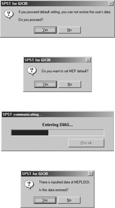
4.1. Default setting
SPST can restore the factory settings.
This function
1.Deletes all user data in the file system;
2.Restores all WAP settings to default; and
3.Restores the values set by the user to default;
(MEP_LOCK settings and the destination and operator name do not change.)
<Operation>
1)Set the COM port on the SPST initial screen and click “Default Set”.
2)Click “Yes” to proceed. Click “No” to exit.
Figure 7
3) Click “Yes” to back-up the MEPLOCK data. Click “No” to restore default settings.
Figure 8
4) Communication starts.
Figure 9
5) The following appears when you select “Yes” in step 3 and MEPLOCK data exists. Click “Yes” to restore the data.
Figure 10
2 – 5
GX30 |
CONFIDENTIAL |
6) After the handset is turned on, the initialization is complete.
Figure 11
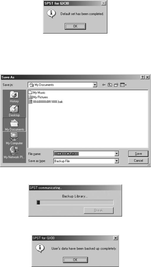
4.2. User data back-up
SPST saves all the data stored on the handset.
1.Set the COM port on the SPST initial screen and click “User Data Back-up”.
2.Specify the file name in the following dialog box and click “Save”.
Figure 12
3. The communicating dialog box appears while processing.
Figure 13
4. When completed, the following message appears. Click “OK”.
Figure 14
2 – 6

CONFIDENTIAL |
GX30 |
4.3. User data restore
SPST completely restores the backed up data.
1.Set the COM port on the SPST initial screen and click “User Data Restore”.
2.Specify the file name in the following dialog box and click “Save”.
Figure 15
3. The communicating dialog box appears while processing.
Figure 16
4. When the restore is complete, click “OK”.
Figure 17
2 – 7
GX30
4.4. Downloader
4.4.1 Introduction
Downloader allows you to upgrade the firmware.
1) Required devices
CONFIDENTIAL
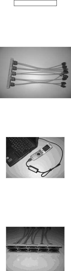
The following devices are required to rewrite MOT files using Communication Box.
Conversion connector (16-pin → 10-pin)
This conversion connector is required to connect GX30 with Communication Box since the cable connector of Communication Box has 16 pins.
Figure 18
2) Connecting handset to a PC
A) Using a cable for upgrading
1.Connect the cable to a PC.
2.Connect the cable to handset.
3.The photo below shows handset connected to a PC.
Figure 19
B) Using Communication Box
1.Connect a PC to Communication Box via a serial cable.
2.Connect the AC charger to Communication Box and then plug it into the outlet. All SET POWER SW on Communication Box must be turned off.
3.Connect the conversion connector to Communication Box Cables. Connect the conversion connector in the following order, label side up. From upper right end: Cable No. 1, 3, 5, 7, and 9.
From lower right end: Cable No. 2, 4, 6, 8, and 10.
Figure 20
2 – 8

CONFIDENTIAL |
GX30 |
4. The photo below shows the conversion connector connected to Communication Box Cable 1.
Figure 21
5. Connect the other end of the conversion connector to handset.
Figure 22
6. The photo below shows handset, Communication Box and a PC (all connected).
Make sure handset and Communication Box Cable 1 are connected via the conversion connector.
Figure 23
[Note]
Handset must be turned off before making any connections.
Press and hold the Power key to turn off handset.
Do not turn off in other ways. Malfunction may occur and the MOT file rewrite operation may fail.
Make sure the handset battery is sufficiently charged.
If the battery is low, the MOT file rewrite operation may fail.
Charge the battery before the operation.
Disconnect the AC charger from a cable for upgrading.
When rewriting MOT files using the upgrading tool, do not connect the AC charger to the cable.
If you connect the cable connected to the AC charger to handset, charging starts and the MOT file rewrite operation is interrupted.
All SET POWER SW on Communication Box must be turned off.
If handset is connected with SET POWER SW turned on, charging starts and the MOT file rewrite operation is interrupted.
Make sure handset and Communication Box Cable 1 are connected via the conversion connector.
(When using Communication Box, the only handset connected to Cable 1 can be operated on the PC.)
2 – 9

GX30
4.4.2 Rewriting MOT files
CONFIDENTIAL
This section describes how to rewrite MOT files using the upgrading tool.
1) Activating Software
1. Double click the shortcut icon on your desktop or click “The GX30 Upgrading Tool” on the Start menu.
Figure 24
2. The upgrading tool is activated.
Figure 25
[Note]
Disable the power saving mode before rewriting MOT files.
If the power saving mode is active, the rewrite operation may fail depending on the PC.
2 – 10
CONFIDENTIAL |
GX30 |
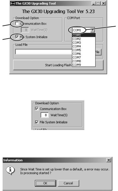
2) Selecting options and COM port
1.Uncheck the check box when using a cable for upgrading. Leave it checked when using Communication Box.
2.To initialize user area, check the File System Initialize check box. (User data will be deleted and the handset status will return to the default.)
3.Click here and in the pull-down list, select a communications port where the cable or Communication Box is connected.
1 |
3 |
2
Figure 26
When using Communication Box, set Wait Time.
Check the Communication Box check box to adjust Wait Time (default: 8 seconds). The time to delete the program data varies between handsets. Handsets wait for the set Wait Time until the whole process is completed. If an error occurs, increase the value.
Figure 27
[Notes for the Wait Time setting]
When the set value is smaller than the default (8), the message on the left appears alerting you a possible error. Click the “OK” button to proceed, and click the “Cancel” button to change the value.
Figure 28
2 – 11
GX30 |
CONFIDENTIAL |
You can shorten time for the MOT file rewrite operation by selecting a smaller value for Wait Time. Example: Time to rewrite two MOT files at a time.
At the default setting (8 seconds), rewrite time is approximately one hour.
If the value is set to 1, the rewrite time will be reduced to approximately 30 minutes. If an error occurs at 1, increase the value.
The error screen will appear on handsets No. 2 to No.10.
If this screen appears, increase Wait Time and retry.
Error screen
Flash Loader 5.02
CORRESPONDENCE_ERROR
Figure 29
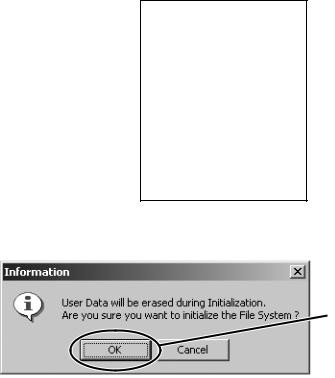
When the File System Initialize check box is checked, a confirmation message appears.
Click the [OK] button.
Figure 30
[Note]
When you check File System Initialize check box and click the “OK” button, handset status returns to the default. In this case, user data is initialized after the MOT file rewrite operation. Uncheck the check box to avoid this.
2 – 12
CONFIDENTIAL |
GX30 |
3) Selecting a MOT file
1.Click the “Select File” button. The Open dialog box appears.
Figure 31
[Open dialog box]
2.Click the “  ” button to open a desired folder.
3.A Motorola file (.mot) in the folder appears. Click a file to write in.
4.Click the “Open” button to open the file.
2
3
4
Figure 32
[Note]
Make sure to select a MOT file.
If the File name field is blank, you cannot rewrite a MOT file.
Use MOT files in the hard disk.
If the selected MOT file is stored in other locations, an error message appears and you cannot complete the rewrite operation.
Figure 33
To use MOT files on CDs or on the network, copy or download them to the hard disk first.
2 – 13

GX30
4) Rewriting a MOT file
CONFIDENTIAL
Click the “Start Loading Flash” button to start rewriting.
Figure 34
1.“Press Power Button” appears. <When using a cable for upgrading>
Hold down the Power key.
<When using the Communication Box>
Turn on handsets from No.10 down to No.1 (turn on only the handsets you are using).
Figure 35
2.“Keep Pressing Power Button” appears. <When using a cable for upgrading>
Hold down the Power key until the “Keep Pressing Power Button” disappears. <When using the Communication Box>
Leave the handsets turned on.
Figure 36
2 – 14

CONFIDENTIAL |
GX30 |
3.The MOT file rewrite operation starts. <When using a cable for upgrading>
When “Keep Pressing Power Button” disappears, release the Power key. <When using the Communication Box>
Leave the handsets turned on.
Figure 37
4. When the rewrite operation starts, handset display screen shows the software version and process of communications with the PC.
Flash Loader 5.02
XXXXXXXCommand
Figure 38
Canceling the ongoing rewrite operation:
Click the “QUIT” button.
To rewrite MOT files later, remove and install the battery first.
[Notes for the use of a cable for upgrading]
1.Disconnect the AC charger from the cable. Otherwise charging starts and the MOT file rewrite operation is interrupted.
2.Make sure the handset battery is sufficiently charged.
If the battery is low, the rewrite operation may fail. Charge the battery before the operation.
3.If the ongoing rewrite operation is canceled, or interrupted by an error, remove and reinstall the battery and retry.
[Notes for the use of the Communication Box]
1.When “Press Power Button!” appears, turn on handsets from No.10 down to No.1. If the handset No.1 is first turned on, the rewrite on handsets No. 2 to No. 10 operation will fail.
2.The time to delete the program data varies between handsets. If the process fails at the default Wait Time (8 seconds), increase the value. Consequently, this will increase the time to complete the rewrite operation.
2 – 15
GX30
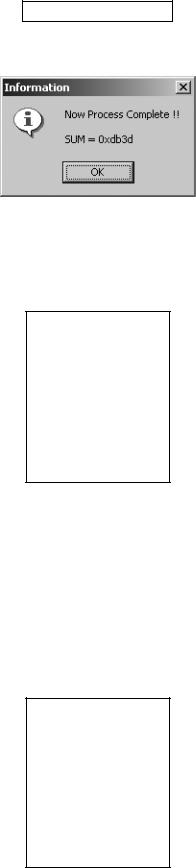
5) Checking the value of SUM
CONFIDENTIAL
When the rewrite operation is completed, a confirmation message appears with SUM.
Figure 39
SUM also appears on handset. <When using a cable for upgrading>
After 8 seconds, SUM disappears. <When using Communication Box>
When SET POWER SW is turned off, SUM disappears.
Flash Loader 5.02
SUM Check End
SUM = 0xdb3d
Figure 40
Make sure SUM is the same between the PC and handset.
The same SUM means that the rewrite operation is completed properly. If the value is different, try again to ensure completion of the operation.
If the MOT file rewrite operation fails, an error message appears on handset.
* The screen shot on the left shows an error in erasing Flash data.
“ADR” and “STR” appear only when an error occurs in the FLASH-related operation. Start over the MOT file rewrite operation.
<When other error messages appear>
Find the message in [4.4.3.2) Error messages for Loading loader (see page 2-18)], and follow the instructions.
Error screen
Flash Loader 5.02
FLASH_ERROR
ERROR_ERASE
ADR = 0x1000000
STR = 0xA0
Figure 41
2 – 16

CONFIDENTIAL |
GX30 |
6) After the operation
Disconnect the cable for upgrading from handset.
When using the Communication Box, turn off SET POWER SW and then disconnect the cable from handset.
7) Initializing only the file system
Follow the instructions below to initialize only the file system.
(User data will be deleted and the handset status will return to the default.)
* Perform this procedure when the handset does not turn on.
1.Check the File System Initialize check box.
2.Leave the Load File text box blank.
3.Click the “Start Loading Flash” button.
1
2
3
Figure 42
For further operations, refer to [4.4.2.4) Rewriting a MOT file (see page 2-14)] or [4.4.2.5) Checking the value of SUM (see page 2-16)].
2 – 17
GX30 |
CONFIDENTIAL |
4.4.3 Error message list |
|
Below is the list of error messages for the upgrading tool (on the PC side) and Loading loader (on the handset side).
1) Error messages for the upgrading tool (on the PC side)
No. |
Message |
Descriptions/Instructions |
1 |
Select a file for Downloading or check the box of Initializing. |
Load File is not set. |
|
|
Select a MOT file. |
2 |
Unable to open file. |
Failed to open the MOT file. |
|
|
Start over the rewrite operation. |
3 |
You need to set the Wait Time! |
WaitTime (S) is not set. |
|
|
Set WaitTime (S) value. |
4 |
The file you selected is unsuitable for Upgrading. |
The selected file cannot be rewritten for upgrading. |
|
|
Select an appropriate MOT file. |
5 |
Cannot Setup COM port. |
The selected COM port does not exist or is used for other opera- |
|
|
tions. |
|
|
Select a COM port connected to the PC cable. |
6 |
RAM Loader not responding to Commands. |
No response from Loading loader. |
|
|
Start over the rewrite operation. |
7 |
RAM Loader responding Parameter Error. |
Information sent from the PC is illegal. |
|
|
Reinstall the upgrading tool. |
|
|
Start over the rewrite operation. |
8 |
RAM Loader responding Flash Error (XXXX). |
Failed to initialize FLASH ROM in (XXXX). |
|
|
Start over the rewrite operation. |
9 |
Correspondence Error. |
Undefined response from Loading loader. |
|
|
Start over the rewrite operation. |
2) Error messages for Loading loader (on the handset side)
No. |
Message |
Descriptions/Instructions |
1 |
FLASH_ERROR |
An error in Flash Rom. |
|
|
Start over the rewrite operation. |
2 |
ERROR_PARAM |
The upgrading tool is damaged. |
|
|
Uninstall and reinstall the upgrading tool, and start over the rewrite |
|
|
operation. |
3 |
ERROR_WPROTECT |
Flash Rom is protected. |
|
|
Battery may be too low. |
|
|
Use a sufficiently charged battery and start over the rewrite opera- |
|
|
tion. |
4 |
ERROR_READ |
Failed to read Flash Rom data and the operation was aborted. |
|
|
Start over the rewrite operation. |
5 |
ERROR_WRITE |
Failed to write to Flash Rom and the operation was aborted. |
|
|
Start over the rewrite operation. |
6 |
ERROR_ERASE |
Failed to erase Flash Rom data and the operation was aborted. |
|
|
Start over the rewrite operation. |
7 |
ERROR_VERIFY |
The rewrite operation was aborted since there was a mismatch |
|
|
between data written to Flash Rom and that written to handset. |
|
|
Start over the rewrite operation. |
8 |
ERROR_RWE_TMOUT |
Communication was terminated since there was no response from |
|
|
Flash Rom for a certain period of time. |
|
|
Start over the rewrite operation. |
9 |
CORRESPONDENCE_ERROR |
Communication was terminated since serial data communication |
|
|
failed. |
|
|
Start over the rewrite operation. |
10 |
ADR = XXXXXXXX |
Indicates the address of Flash (the error source). |
11 |
STR =XX |
Indicates the status of Flash (the error source). |
*When No.1 occurs, handset screen shows error messages for No.2 to No.8 as well as the address (No.10) and status (No.11) of the error source at the same time.
2 – 18

CONFIDENTIAL |
GX30 |
4.5. RF calibration & check
Stabilized power supply |
RF cable |
|
|
Handset |
GSM tester |
|
Test battery
Data cable
PC
Figure 43
4.5.1 Preparation
•Connect PC and GSM tester with a GPIB cable.
•Connect PC and handset with a Data cable. (Use a test battery or one close.)
•Connect a RF cable of GSM tester to handset.
GPIB cable
2 – 19

GX30
4.5.2 Default setting for the program.
•Activate the program and set defaults.
CONFIDENTIAL
1)Select the COM port.
2)Set the GPIB No.

 3) Select the test instrument.
 4) Set the GPIB address.
5) Set the "Cable Offset" values. For cables with connector QCNWK0138AFZZ/ QCNWK0136AFZZ, set the values as follows:
GSM 900: 0.60
DCS 1800: 0.95
PCS 1900: 0.96
GSM 850: 0.60
6)Auto Dial Setting
When the Auto Dial check box is checked, an entered number is automatically dialed for performance check.
7)Number Setting
Enter a number for Auto Dial.
Figure 44
2 – 20

CONFIDENTIAL |
GX30 |
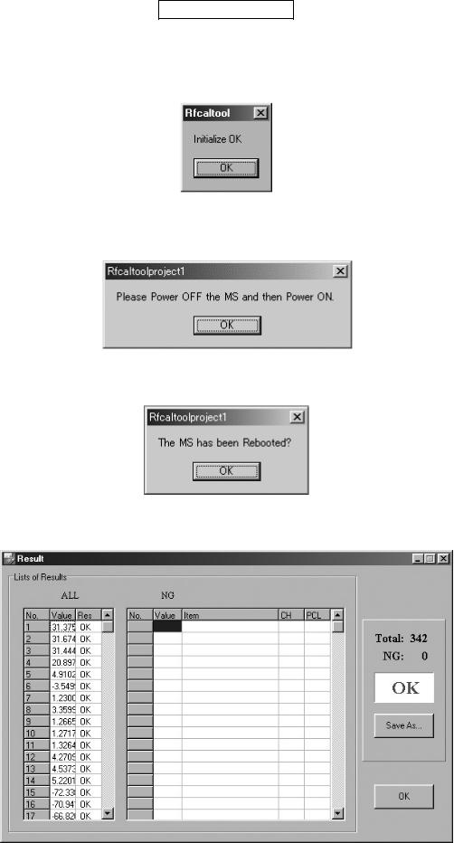
4.5.3 RF calibration
1.Apply 4 V using a stabilized power supply and turn on the handset.
2.Start “RF calibration & check” on SPST and click “Calibration”.
3.When initialization is complete, click “OK”.
Figure 45
4. Apply 4 V using a stabilized power supply and turn on the handset. After the handset enters Standby mode, lower the voltage to 3.7 V, click “OK”.
Figure 46
5.Make sure the handset is on and click “OK”. (Adjustment starts.)
Figure 47
6. Click “OK”.
Figure 48
7. The initial screen returns.
<Note>
The following appears when the handset software (mot) is outdated. Upgrade to a new version.
Figure 49
2 – 21
GX30
4.5.4 RF performance check
CONFIDENTIAL
1.Apply 4 V using a stabilized power supply and turn on the handset.
2.Start “RF calibration & check” on SPST and click “Check”.
3.When initialization is complete, click “OK”.
Figure 50
4.Apply 4 V using a stabilized power supply and turn on the handset. After the handset enters Standby mode, lower the voltage to 3.7 V, enter the PIN code and click “OK”.
Figure 51
5. Make sure the handset is in the idle mode and click “OK”.
Figure 52
6. RF performance check is complete. Click “Save As...” and name the file to save the result. Click “OK” to exit.
Figure 53
2 – 22
Loading...