


SJ-40J-GY/ BE
SJ-W40J-GY/ BE
SJ-36J-GY/ BE
SJ-W36J-GY/ BE


 SERVICE MANUAL
SX885SE39JPZL
REFRIGERATOR-FREEZER
MODELS SJ-40J-GY/BE
SJ-36J-GY/BE
SJ-W40J-GY/BE
SJ-40J |
SJ-W40J |
SJ-W36J-GY/BE |
|
|
|
|
|
In the interests of user-safety (Required by safety regulations in some |
|
|
countries) the set should be restored to its original condition and only |
|
|
parts identical to those specified should be used. |
DESTINATION ................ |
L |
SJ-36J SJ-W36J
Refrigerant; HFC-134a
Refer to "HFC-134a COOLING UNIT" Service Manual for handling this refrigerant.
TABLE OF CONTENTS |
|
|
page |
SPECIFICATIONS ...................................................................................................................................... |
2 |
DESIGNATION OF VARIOUS PARTS ........................................................................................................ |
3 |
LIST OF ELECTRICAL PARTS ................................................................................................................... |
4 |
WIRING DIAGRAM ..................................................................................................................................... |
5 |
FUNCTIONS ............................................................................................................................................... |
7 |
ASSEMBLING PROCEDURES OF MAIN PARTS AND CAUTIONS .......................................................... |
14 |
COOLING UNIT .......................................................................................................................................... |
21 |
REPLACEMENT PARTS LIST .................................................................................................................... |
22 |
SHARP CORPORATION
1

SJ-40J-GY/ BE
SJ-W40J-GY/ BE
SJ-36J-GY/ BE
SJ-W36J-GY/ BE
SPECIFICATIONS
|
|
Items |
|
|
SJ-40J |
SJ-W40J |
SJ-36J |
|
SJ-W36J |
|
|
|
|
|
Type |
|
|
2-Door |
|
2-Door |
|
|
|
||
|
|
Outer dimensions |
|
Height |
1725mm(67.9") |
|
1585mm(62.4") |
|
|
|
||
|
|
(Including spacer) |
|
Width |
590mm(23.2") |
|
590mm(23.2") |
|
|
|
||
|
|
|
|
|
|
|
|
|
|
|
||
|
|
|
|
Depth |
695mm(27.4") |
|
695mm(27.4") |
|
|
|
||
|
|
Rated storage volume |
|
|
368 liter(13.0 cu.ft) |
330 liter(11.7 cu.ft) |
|
|
||||
|
|
|
|
|
|
F: 96 liter (3.4 cu.ft) |
F: 96 liter(3.4 cu.ft) |
|
|
|||
|
|
|
|
|
|
R: 272 liter(9.6 cu.ft) |
R: 234 liter(8.3 cu.ft) |
|
|
|||
|
|
|
|
|
|
|
|
|
|
|
|
|
|
|
Defrosting |
|
System |
Heater system |
|
|
|
|
|
|
|
|
|
|
|
Start |
Automatic |
|
|
|
|
|
|
|
|
|
|
|
Finish |
Automatic |
|
|
|
|
|
|
|
|
|
Temperature control |
|
|
Automatic (Adjustable) |
|
|
|
|
|
||
|
|
No-frost freezer |
|
|
Yes |
|
|
|
|
|
|
|
|
|
Interior lamp |
|
|
1 |
|
|
|
|
|
|
|
|
|
|
|
|
|
|
|
|
|
|
|
|
|
|
Evaporating pan |
|
|
1 |
|
|
|
|
|
|
|
|
|
Refrigerator |
|
R tray |
3 |
|
2 |
|
|
|
|
|
|
|
Compartment |
|
Fresh case |
1 |
|
1 |
|
|
|
|
|
|
|
|
|
Vegetable case |
1 |
|
1 |
|
|
|
|
|
|
|
|
|
Door pocket |
3 |
|
2 |
|
|
|
|
|
|
|
|
|
Egg tray |
1 |
|
1 |
|
|
|
|
|
|
|
|
|
Bottle pocket |
1 |
|
1 |
|
|
|
|
|
|
|
Freezer |
|
Ice cube maker |
1 |
|
1 |
|
|
|
|
|
|
|
Compartment |
|
Freezer case |
1 |
|
1 |
|
|
|
|
|
|
|
|
|
Freezing case |
1 |
|
1 |
|
|
|
|
|
|
|
Deodorizing system |
|
|
No |
|
|
|
|
|
|
|
|
|
R&L door / Dual Swing Door |
No |
Yes |
No |
|
Yes |
|
|
|||
|
|
COLOR |
|
|
|
|
|
|
|
|
|
|
|
|
Items |
|
SJ-40J/ W40J/ 36J/ W36J-GY |
SJ-40J/ W40J/ 36J/ W36J -BE |
|
|
|
||||
|
|
Outside color |
|
Gray |
|
Beige |
|
|
|
|
|
|
|
|
Inside color |
|
White |
|
White |
|
|
|
|
|
|
|
|
RATING |
|
|
|
|
|
|
|
|
|
|
|
|
Items |
|
|
SJ-40J |
SJ-W40J |
SJ-36J |
|
SJ-W36J |
|
|
|
|
|
Rated voltage |
|
(V) |
220-240 |
|
|
|
|
|
|
|
|
|
Rated frequency |
|
(Hz) |
50 |
|
|
|
|
|
|
|
|
|
Climate class |
|
|
T |
|
|
|
|
|
|
|
|
|
Rated input of motors |
|
(W) |
160-166 |
|
|
|
|
|
|
|
|
|
Rated input of heaters |
|
(W) |
133-158 |
|
|
|
|
|
|
|
|
|
Refrigerant (Charging quantity) |
HFC-134a(110g) |
HFC-134a(110g) |
|
|
|
|||||
|
|
Net Weight |
|
(kg) |
66 |
69 |
62 |
|
65 |
|
|
|
2

SJ-40J-GY/ BE
SJ-W40J-GY/ BE
SJ-36J-GY/ BE
SJ-W36J-GY/ BE
DESIGNATION OF VARIOUS PARTS
The names in parenthesis are the denominations used in the Replacement Parts List.
SJ-40J / W40J |
|
SJ-36J / W36J |
|
|
9 |
|
|
1 |
10 |
|
|
11 |
|
||
2 |
1 |
||
|
|||
10 |
|
||
|
2 |
||
|
|
||
3 |
|
3 |
|
|
4 |
||
4 |
|
||
|
5 |
||
5 |
12 |
||
|
|||
|
|
||
6 |
10 |
6 |
|
|
|
||
7 |
17 |
7 |
|
|
|||
|
|
||
8 |
|
8 |
|
|
|
Figure D-1. External Description
9 |
11 |
10 |
12 |
10 |
17 |
13 |
14 |
15 |
16 |
17 |
1.Light [Lamp]
Use a 10W lamp bulb with E12 base when replacing the lamp bulb . Do use bulbs other than the specified voltage(see affixed label by the bulb)
2.Refrigerator shelf [R tray]
3.Refrigerator temp. control knob 
[R-temp. control knob]
4. Chilled case [Fresh case]
5. Lever [V-case shelf lever]
6.Fruit and vegetable crisper [Vegetable case]
7.Evaporating pan [Evaporating pan)
8.Adjustable feet [Adjustable leg ass’y]
9.Light switch [Door switch]
10.Free pocket [R door pocket]
11.Egg holder [Egg tray]
12.Bottle pocket [Bottle pocket]
13.Freezer temp. control knob[F-temp. dial ass’y]
14.Ice cube maker [Ice cube maker]
15.Stainless steel freezer case [Freezer case ass'y]
16.Freezer case [Freezing case]
17.Magnetic door seal [R-door packing/ F-door packing]
Mark: Cold air flow
Lamp |
Door switch |
|
Damper thermostat
Defrost timer
V-heater
F-thermostat
Fan motor
Defrost thermostat 

Fuse ass'y
Def. heater ass'y
Compressor
Protector
Starting relay
Figure D-2. Constructions
3
SJ-40J-GY/ BE
SJ-W40J-GY/ BE
SJ-36J-GY/ BE
SJ-W36J-GY/ BE
LIST OF ELECTRICAL PARTS
ITEMS |
TYPE NAME |
|
RATING |
SPECIFICATIONS |
|
R-door switch |
PS 102-S |
125V-1A,250V-0.5A |
2 terminals type push-button |
|
|
F-Thermostat |
MM1-8109 |
125V-6A,250V-3A |
ON : -15˚C , OFF : -20˚C |
|
|
Defrost heater |
— |
220-240V |
378Ω |
|
|
Damper thermostat |
MM1-6164 |
— |
|
Open : Max -0.5˚C , Close : -5˚C |
|
|
|
|
|
|
|
Defrost timer |
TMDF704FD2 |
220-240V |
Integration type |
|
|
|
|
50/ 60Hz |
Cycle time : 8h48m/7h20m(50/60Hz) |
||
|
|
|
|
Delay time : 4m50s/4m2s(50/60Hz) |
|
Lamp socket |
— |
250V |
1A |
E-12 |
|
Lamp |
— |
240V |
10W |
E-12 |
|
Defrost thermostat |
US602S |
125V |
15A |
Open : 10˚C , Close : 1˚C |
|
Thermo. fuse |
— |
250V |
10A |
Cut off temperature : 70˚C or 72˚C |
|
Fan motor |
3R00044B |
220-240V/ 50Hz |
|
|
|
Compressor |
GLY-70AA |
220-240V/ 50Hz |
Main : 13.9 Ω (20˚C) |
*1 |
|
|
|
|
|
Aux : 17.9 Ω (20˚C ) |
|
Starting relay |
3003-7 |
— |
|
14Ω |
|
Protector |
4TM-308NFB-YY |
— |
|
120˚C / 65˚C |
|
V-heater |
A202 |
220-240V 8000Ω |
|
|
|
|
|
6.0-7.2W |
|
|
|
C-thermostat |
US602S |
250V |
8A |
Open : 25˚C , Close : 17˚C |
|
A018 / A133 / A043
*1 COIL POSITION OF COMP.
Common
Aux. coil |
Main coil |
4
SJ-40J-GY/ BE
SJ-W40J-GY/ BE
SJ-36J-GY/ BE
SJ-W36J-GY/ BE
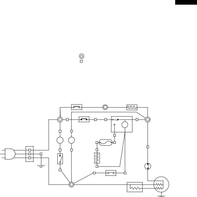
WIRING DIAGRAM
Be sure to replace the electrical parts with specified ones for maintaining the safety and performance of the set.
G : GRAY |
CONNECTED IN TERMINAL BOX |
|||
Br : BROWN(live) |
||||
YG : YELLOWISHGREEN |
CONNECTOR |
|
||
Y |
YELLOW |
|
|
|
R |
: RED |
|
|
|
P |
: PINK |
|
|
|
B |
: BLUE(neutral) |
|
|
|
Bk : BLACK |
|
|
|
|
S-B : SKY-BLUE |
|
|
|
|
G-Y : GREEN-YELLOW(earth) |
|
|
|
|
W : WHITE |
|
|
|
|
O : ORANGE |
|
|
|
|
|
|
C-thermostat |
(O) |
V-heater |
Terminal block
E
Source cord
(BR) |
F-thermostat |
(R) |
Defrost timer |
|
|
(G) |
|
|
|
|
|
|
|
|
TM |
Lamp |
FM Fan motor |
Thermo.fuse |
|
|
|
L |
|
|
|
|
|
(S-B) |
(O) |
(W) |
(BK) |
|
|
|
|
|
Defrost heater |
|
|
Door |
|
|
(Y) |
|
Protector |
|
|
|
|
||
switch |
|
|
|
|
|
|
|
|
Defrost thermostat |
|
Compressor |
|
|
|
Starting relay |
C |
|
|
|
|
|
||
|
|
|
|
M |
|
|
|
|
|
|
|
|
(B) |
|
|
|
A |
|
|
|
|
|
|
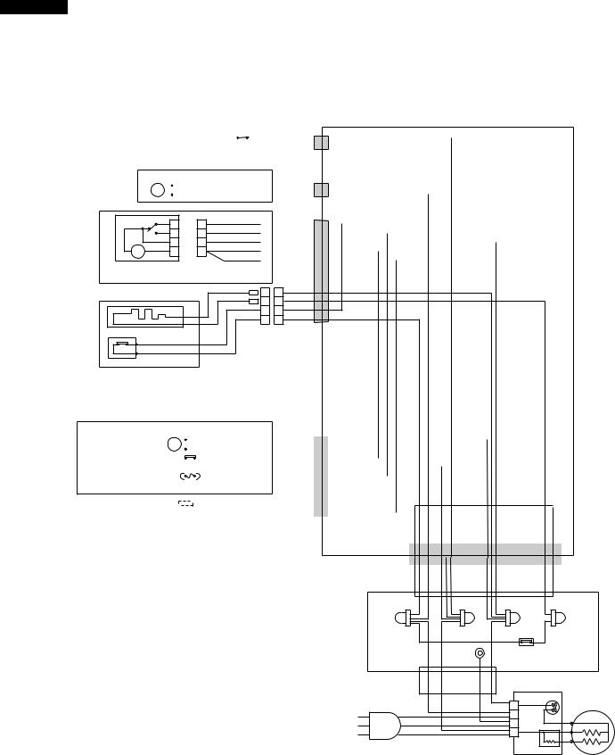
Figure W-1. Wiring Diagram
5
SJ-40J-GY/ BE
SJ-W40J-GY/ BE
SJ-36J-GY/ BE
SJ-W36J-GY/ BE
Cabinet ass'y
R-door switch |
|
|
|
|
1 |
|
1 |
B-1 |
|
|||
|
|
|
|
2 |
|
2 |
S-B-1 |
|
||||
Multi-louver ass'y |
|
|
|
|
|
|||||||
Lamp |
Socket ass'y |
|
|
|
(S-B-1) |
|
||||||
L |
|
|
|
|
|
|
|
1 |
|
1 |
|
|
|
|
|
|
|
|
|
Br-1 |
|
||||
|
|
|
|
|
|
|
2 |
|
2 |
|
||
|
|
|
|
|
|
|
|
|
|
|||
|
|
|
|
|
|
|
|
|
|
|
||
|
3 |
TM |
4 2 |
1 |
Defrost timer RC box ass'y
1 4 2 3
D timer lead ass'y
1 |
|
1 |
R-1 |
|
|
|
|
Bk-1 |
|
|
|||||
2 |
|
2 |
|
|
|||
G-1 |
|
|
|||||
3 |
|
3 |
|
|
|||
|
|
|
|||||
4 |
|
4 |
Y-1 |
|
|
|
|
Y-2 |
|
|
|||||
5 |
|
5 |
|
|
|||
|
|
|
|
|
|||
6 |
|
6 |
|
|
|
|
|
11 G-3
22 O-1
33 (R-1)
44 Br-2
V heater
Lead wire
FC-box ass'y
F-thermostat
C-partition ass'y
EV-cover ass'y
|
|
|
|
|
|
|
Lead wire |
|
|
|
|
|
|
|
|
|
|
|
|
|
|
|||
|
|
|
|
|
|
|
EV-cover ass'y |
|
|
|
G-2 |
|
|
|
|
|
|
|
|
|
||||
Fan motor |
|
FM |
|
1 |
|
1 |
|
|
|
|
|
|
|
|
|
|
||||||||
|
|
|
|
|
|
B-2 |
|
|
|
|
|
|
|
|
|
|||||||||
2 |
|
2 |
|
|
|
|
|
|
|
|||||||||||||||
Def. thermo. ass'y |
|
|
|
|
|
|
|
|
|
|
3 |
|
3 |
(Y-1) |
|
|
|
|
|
|
|
|
|
|
|
|
|
|
|
|
|
|
|
|
4 |
|
4 |
B-3 |
|
|
|
|
|
|
|
|
|
||
|
|
|
|
|
|
|
|
|
|
|
|
|
|
|
|
|
|
|||||||
|
|
|
|
|
|
|
|
|
|
|
|
(Bk-1) |
|
|
|
|
|
|
|
|
|
|
||
|
|
|
|
|
|
|
|
|
|
|
|
|
|
|
|
|
|
|
|
|
|
|||
Fuse ass'y |
|
|
|
|
|
|
|
|
|
|
5 |
|
5 |
|
|
|
|
|
|
|
|
|
||
|
|
|
|
|
|
|
|
|
|
6 |
|
6 |
W-1 |
|
|
|
|
|
|
|
|
|
|
|
|
|
|
|
|
|
|
|
|
|
|
|
|
|
(W-1) |
|
|
|
|
|
|
|
|
|
|
Def. heater ass'y |
|
|
|
|
|
|
|
|
|
1 |
|
1 |
(Y-2) |
|
|
|
|
|
|
|
|
|
|
|
|
|
|
|
|
|
|
2 |
|
2 |
|
|
|
|
|
|
|
|
|
||||||
|
|
|
|
|
|
|
|
|
|
|
|
|
|
|
|
|
|
|
|
|
|
|
||
|
|
|
|
|
|
|
|
|
|
|
3 |
|
3 |
|
|
|
|
|
|
|
|
|
|
|
|
|
|
|
|
|
|
|
|
|
|
4 |
|
4 |
|
|
|
|
|
|
|
|
|
|
|
|
|
|
|
|
|
|
|
|
|
|
|
|
|
|
|
|
|
|
|
|
|
|
|
|
|
|
|
|
|
|
|
|
|
|
|
|
|
|
|
|
|
|
|
|
|
|
|
|
|
|
|
|
|
|
|
|
|
|
|
|
|
|
|
|
|
|
|
|
|
|
|
|
|
|
|
|
|
|
Terminal box |
G : GRAY |
Brown |
Blue |
Gray |
Orange |
Br : BROWN(live) |
|
|
|
|
O : ORANGE |
|
|
|
|
Y : YELLOW |
|
Earth |
C-thermostat |
|
R : RED |
|
|||
|
|
|
|
|
B : BLUE(neutral) |
|
|
|
|
Bk : BLACK |
|
|
|
Protector |
S-B: SKY-BLUE |
|
|
|
|
|
|
1 |
Compressor |
|
G-Y: GREEN-YELLOW(earth) |
|
|
L |
C |
|
|
E |
||
|
|
|
|
|
W : WHITE |
|
|
N |
M |
Source cord |
|
A |
||
|
|
Starting relay |
||
|
|
|
||
|
|
|
Terminal block |
|
Figure W-2. Electric Accessories Layout
6
SJ-40J-GY/ BE
SJ-W40J-GY/ BE
SJ-36J-GY/ BE
SJ-W36J-GY/ BE
FUNCTIONS
1. ADJUSTABLE TEMPERATURE CONTROL
(1) Temperature control of freezer
 Thermostat (senses freezer temperature) operates on ON/OFF switchover to control the compressor and allows the freezer temperature to keep at a suitable temperature.
 However adjust the freezer temp. control knob as follows depending upon the storing condition of foods.
|
FREEZER TEMP. CONTROL |
|
KNOB |
PURPOSE |
|||
|
|
||||||
|
|
SETTING |
|
||||
|
MIN |
|
|
|
MAX |
|
|
|
|
|
|
|
|||
|
|
|
2 |
7(MAX) |
For making ice rapidly or fast freezing. |
||
5 |
4 |
3 |
|
||||
|
4(MED) |
For normal freezing. |
|||||
|
|
|
|
|
|
||
|
|
|
|
|
|
|
|
|
|
|
|
|
|
1(MIN) |
When frozen food or ice cream is not stored. |
|
|
|
|
|
|
|
|
Figure F-1.
(2) Temperature control of refrigerator
 Damper-thermostat senses temperature of the refrigerator and changes the opening angle of the damper automatically.
However, as the Damper-thermostat has no function to switch on or off the compressor and cool air circulating fan, the freezer temperature control causes temperature in the refrigerator to vary to some extent.
 However, adjust the refrigerator temp. control knob as follows depending upon the cooling condition.
|
|
|
MED |
|
|
||||
|
|
|
KNOB |
PURPOSE |
|||||
|
|
|
4 |
5 |
|||||
3 |
|
|
|
SETTING |
|
||||
|
|
|
|
|
|||||
|
|
|
|
|
|
|
|
|
|
2 |
|
|
|
6 |
7(Coldest) |
For keeping foods fresher tasting. |
|||
|
|
|
|
|
|
CHILLED |
|
When the refrigerator does not provide sufficient cooling. |
|
|
|
MIN 1 |
|
|
|
ZONE |
|
||
|
|
|
|
|
7 Coldest |
|
|
||
4(MED) |
For normal operation. |
||||||||
|
|
REFRIGERATOR |
|||||||
|
|
TEMP.CONTROL |
1(MIN) |
When the refrigerator provides excessive cooling. |
|||||
|
|
|
|
|
|
|
|||
|
|
Figure F-2. |
|
|
|||||
|
|
|
|
||||||
NOTE: |
The refrigerator temperature is affected also by the freezer temperature. If the freezer temp. |
||||||||
|
|
|
control knob is set at the position "MAX", the temperature tends to be lower than the following |
||||||
|
|
|
values, and if set at near the position "MIN", temperature tends to be higher. |
||||||
 If the refrigerator is operated for a long time with the freezer temperature control sets the "MAX" position, foods stored in the refrigerator compartment may also freeze.
 When refrigerator temperature control sets to the "Coldest", some foods stored may freeze. In this case adjust control set back to the "MED" position.
 When refrigerator temperature control sets to the "Coldest", some foods stored in fresh cases may also become frozen.
(3) Reference value of temperature
SETTING OF |
7(MAX) |
4(MED) |
1(MIN) |
FREEZER TEMP. |
|||
CONTROL KNOB |
|
|
|
Freezer |
Approx. |
Approx. |
Approx. |
temperature |
-21˚C |
-18˚C |
-15˚C |
|
|
|
|
SETTING OF |
|
|
|
REFRIGERATOR TEMP. |
7(Coldest) |
4(MED) |
1(MIN) |
CONTROL KNOB |
|
|
|
Refrigerator |
Approx. |
Approx. |
Approx. |
temperature |
0˚c |
3˚c |
6˚c |
|
|
|
|
The values shown above refer to the case where the freezer temp. control knob is set at "MED".
The values shown above refer to the measurement carried out center area and 1/3 of overall height from the bottom at each of the refrigerator and the freezer after machine has been operated at an ambient temperature of 30˚C with no food stored and the door closed until the temperature is stabilized.
The values vary depending upon frequency of opening and closing the door, ambient temperature, amount of stored foods and manner of storing foods.
7
SJ-40J-GY/ BE SJ-W40J-GY/ BE SJ-36J-GY/ BE SJ-W36J-GY/ BE
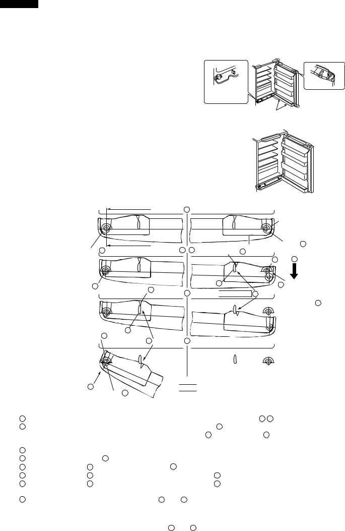
2. R & L DOOR / DUAL SWING DOOR
(1). Structure
Note
 Do not destroy or damage the refrigerator body's structure or internal structure intentionally.
 Do not put any objects on the lower hinge or lower hinge pin.
 Please pay attention to the lower hinge pin and the cam, do not let them get stuck.
 Do not add oil to the refrigerator body, pulley, lower hinge, since the plastic components will be influenced by different kinds of oil.
Do not open the door of the refrigerator compartment forcibly, the door may fall off or cause the personal injury.
If the door can not be opened, please check the part shown on the right figure to see if it is got stuck by the foreign objects.
|
I |
1 |
|
L |
|
Door cam projection |
A' |
2 3 |
Groove D |
Door cam projection B' |
|
|
3 |
|
|
|
|
Hinge projection b' |
|
|
Hinge projection |
a' |
|
The explanation of the operation manual
R&L structure of the |
R&L structure of |
|
refrigerator body |
||
the door |
||
|
||
Cam |
|
|
(hinge projection) |
(Positioned at the |
|
|
||
Lower hinge pin |
four corners of the door) |
|
Lower hinge |
|
|
Pulley |
|
Figure F-3
Figure F-4
|
Hinge pin |
|
|
Door cam Door cam projection A |
|
Door cam projection B |
|
|
|
Groove C |
2 |
Hinge |
|
|
projection b |
3 |
-1 |
|
||

 approx. 2mm 3 -2
 Hinge projection a
3 -3 |
3 |
3 -4
Door cam projection A'
 means the part of the main body side.
Figure F-5
1 The hinge pins on both right and left sides are supported with the projection A A'of the door cam.
2When the door is pulled, the hinge pin is guided to the groove C and the door is moved approx. 2 mm sideward. When the hinge pin is engaged with the “J shaped” groove D of the projection A'of the door cam on the opposite side, the door will be locked.
3According to the opening degree of the door,
3 |
-1: Hinge pin and groove C |
|
3 |
-2: Hinge projection |
b and door cam projection B |
3 |
-3: Hinge projection |
b' on the opposite side and the projection A'of the door cam |
3 |
-4: Hinge projection |
a' on the opposite side and the projection A'of the door cam |
Any one of the above guides keeps the stage in which the door is moved approx. 2 mm sideward.
4 When the door is closed, the procedure of 1 |
thru 3 is reversed. |
|
|
|
|
|
Even if the left and right doors are opened at the same time, both doors do not get off since the |
|
|
width dimension between the projections |
A and A' of the door cam is small than that between the |
|
left and right hinge pins. |
|
|
|
|
8
SJ-40J-GY/ BE
SJ-W40J-GY/ BE
SJ-36J-GY/ BE
SJ-W36J-GY/ BE
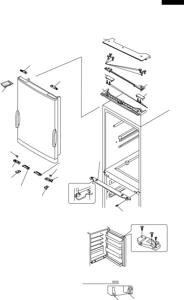
(2)Disassembly, assembly and adjustment of R & L door 1List of parts concerned with R & L door
Top hinge cover
Door cam tr |
Special screw |
|
Hinge cam tl |
|
cam tl |
|
Top hinge ass' |
|
Table support |
Silicon grease |
Hinge cam tr |
(Before replacing door, |
|
also prepare silicon grease. |
|
|
Special screw |
Door cam support
Bottom hinge |
Body |
ass'y |
|
Roller r ass'y
Door cam bl
R-door stopper l 
Door cam support
Door cam br |
Hinge pin
Roller l ass'y
R-door stopper l
Hinge projection
Screw
Figure F-6
2Installation and removal of R & L door
(1)Open the door.
(2)Remove the door cam. (3 screws)
(3)Close the door, and open its opposite side.
In this time, hold the door with both hands to prevent the door from falling.
NOTE  When replacing the door with the new one, coat grease on the slide surface. (Grease all door arms on the four corners.)
(4)Pull off the door upward.
(5)For installation, reverse the above procedure.
The door cam tr is shown here.
Figure F-7
Greasing surface
The door cam tr is shown here.
All around the |
All around the side |
side surface |
surface, and bottom |
|
surface |
Figure F-8
9
SJ-40J-GY/ BE
SJ-W40J-GY/ BE
SJ-36J-GY/ BE
SJ-W36J-GY/ BE
3Removal and installation of Bottom hinge ass'y and Top hinge ass'y
Remove the relevant screws.
NOTE |
After replacement, adjust the position relationship of the door. (Refer to the next item.) |
|
Proper climbing width of roller: 1 to 1.5 mm |
|
Tolerance of climbing width of left and right rollers: within 0.5 mm |
4Adjusting method of R&L door
If any heaviness is felt during opening/closing of the R&L door, any different weight is felt between leftward/ rightward openings, any large drop of the roller felt or any other abnormality is felt, adjust the following.
NOTE |
It must not be skipped or forgot to install any concerned part. Otherwise, it will cause the door to get off. |
|
CAUSE 1. The floor surface is not horizontal. Not level. |
—> The refrigerator is twisted. |
|
2.The climbing width of the roller of the R&L door is larger or smaller than specified. (Proper climbing width: 1 to 1.5 mm)
(1) CAUSE 1; Adjust the adjustable legs as shown in the right.(Figure F-9)
If it can not be adjusted with the adjustable legs, proceed with the following work.
Left side is |
|
|
|
|
|
|
|
Right side is |
|||||||||||||||||||
heavy. |
|
|
|
|
|
|
|
heavy. |
|||||||||||||||||||
|
|
|
|
|
|
|
|
|
|
|
Project the right |
Project the left |
|
|
|
|
|
|
|
|
|
|
|
||||
|
|
|
|
|
|
|
|
|
|
|
adjustable leg. |
adjustable leg. |
|
|
|
|
|
|
|
|
|
|
|
||||
|
|
|
|
|
|
|
|
|
|
|
|
|
|
|
|
|
|
|
|
|
|
|
|
|
|
|
|
|
|
|
|
|
|
|
|
|
|
|
|
|
|
|
|
|
|
|
|
|
|
|
|
|
|
|
|
|
|
|
|
|
|
|
|
|
|
|
|
|
|
|
|
|
|
|
|
|
|
|
|
|
|
|
|
|
|
|
|
|
|
|
|
|
|
|
|
|
|
|
|
|
|
|
|
|
|
|
|
|
|
|
|
|
|
|
|
|
|
|
|
|
|
|
|
|
|
|
|
|
|
|
|
|
|
|
|
|
|
|
|
Figure F-9
(2) CAUSE 2; Check the climbing width of the roller.Check the left and right rollers as a pair. The service kit (CSOG-C803CBK0) is necessary.
Procedure outline (Cause 2)
|
|
Smaller |
|
|
||
(2) Check the climbing |
|
|
(3) -1 |
Insert the spacer |
|
|
|
|
|
||||
width of the roller. |
|
|
|
into the roller assembly. |
||
(1 to 1.5 mm as proper) |
Larger |
|
|
|||
|
|
|
|
|||
|
|
|
(3) -2 |
Insert the spacer |
||
|
|
|
||||
under the door cam.
(4) Check the door opening/closing. (Opening/closing weight, self-closing force, climbing
width of roller and left/right balance)
(5) Adjust the upper hinge.
(If the clearance on the hinge is smaller, insert the spacer.)
(The difference between the climbing widths of the left and right rollers is 0.5 mm or less.)
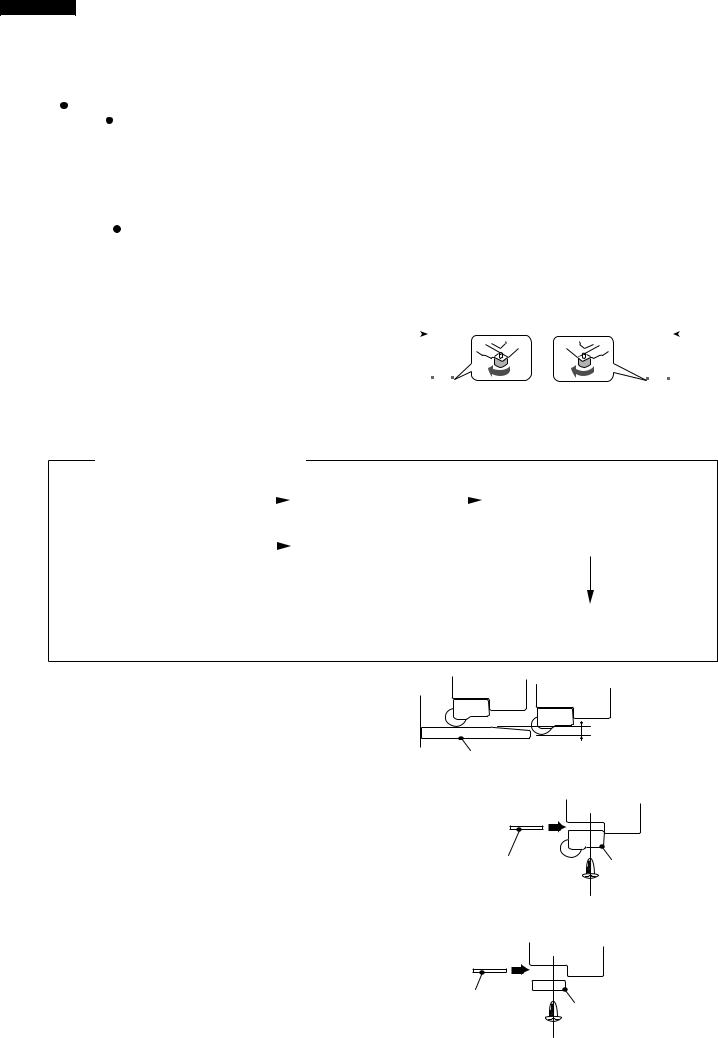
(3)-1 The climbing width is smaller.
Insert the roller spacer between the roller assembly and door.(Insert plural spacers according to the climbing width.)
R & L door
1 ~ 1.5mm
Lower hinge ass'y
Figure F-10
R & L door
(3)-2 The climbing width is larger.
Insert the door cam spacer between the door cam bottom and door. (Insert plural spacers according to the climbing width.)
[Note] • Don’t tighten any M3 flush screw strongly. Otherwise, the screw will become idle.
Roller spacer |
Roller assembly |
(0.5 mm thick Left and |
|
right as symmetric) |
|
Figure F-11 |
|
R & L door |
|
Door cam spacer |
Door cam bottom |
|
(Align the door to |
||
|
||
0.5 mm thick corner R.) |
|
Figure F-12
10
 Loading...