SGS Thomson Microelectronics BZW50-82B, BZW50-47, BZW50-39B, BZW50-39, BZW50-33B Datasheet
...
® |
BZW50-10,B/180,B |
|
|
|
|
TRANSILTM
FEATURES
■PEAK PULSE POWER : 5000 W (10/1000μs)
■STAND-OFF VOLTAGE RANGE :
From 10V to 180V
■UNI AND BIDIRECTIONAL TYPES
■LOW CLAMPING FACTOR
■FAST RESPONSE TIME
■UL RECOGNIZED
DESCRIPTION |
|
Transil diodes provide high overvoltage protection |
R6 |
by clamping action. Their instantaneous response |
|
to transient overvoltages makes them particu- |
|
larly suited to protect voltage sensitive devices |
|
such as MOS Technology and low voltage sup- |
|
plied IC’s.
ABSOLUTE MAXIMUM RATINGS (Tamb = 25°C)
Symbol |
Parameter |
|
Value |
Unit |
|
|
|
|
|
PPP |
Peak pulse power dissipation (see note 1) |
Tj initial = Tamb |
5000 |
W |
|
|
|
|
|
P |
Power dissipation on infinite heatsink |
Tamb = 75°C |
6.5 |
W |
|
|
|
|
|
IFSM |
Non repetitive surge peak forward current |
tp = 10ms |
500 |
A |
|
for unidirectional types |
Tj initial = Tamb |
|
|
Tstg |
Storage temperature range |
|
- 65 to + 175 |
°C |
Tj |
Maximum junction temperature |
|
175 |
°C |
TL |
Maximum lead temperature for soldering during 10s at 5mm |
230 |
°C |
|
|
from case |
|
|
|
|
|
|
|
|
Note 1 : For a surge greater than the maximum values, the diode will fail in short-circuit.
THERMAL RESISTANCES
Symbol |
Parameter |
Value |
Unit |
|
|
|
|
Rth (j-l) |
Junction to leads |
15 |
°C/W |
Rth (j-a) |
Junction to ambient on printed circuit. Llead = 10 mm |
65 |
°C/W |
February 2003Ed : 4A |
1/5 |

BZW50-10,B/180,B
ELECTRICAL CHARACTERISTICS (Tamb = 25°C) |
|
|
|
|
I |
|
|
|
|
|
||||||||||
Symbol |
|
|
Parameter |
|
|
|
|
|
|
|
|
IF |
|
|
|
|
|
|||
|
|
|
|
|
|
|
|
|
|
|
|
|
|
|
|
|||||
|
|
|
|
|
|
|
|
|
|
|
|
|
|
|
|
|
|
|
|
|
VRM |
|
Stand-off voltage |
|
|
|
|
|
|
|
|
|
|
|
|
|
|
|
|||
|
|
|
|
|
|
|
|
|
|
|
VCL |
VBR |
|
|
|
|
|
|
||
VBR |
|
Breakdown voltage |
|
|
|
|
|
|
|
|
|
|
|
|||||||
|
|
|
|
|
|
|
|
VRM |
|
|
V F |
|
|
|
||||||
|
|
|
|
|
|
|
|
|
|
|
|
|
|
|
|
|
|
|||
VCL |
|
Clamping voltage |
|
|
|
|
|
|
|
|
|
|
V |
|||||||
|
|
|
|
|
|
|
|
|
|
|
|
|
|
|
||||||
|
|
|
|
|
|
|
|
|
|
|
|
|
|
|
|
I RM |
|
|
||
IRM |
|
Leakage current @ VRM |
|
|
|
|
|
|
|
|
|
|
|
|||||||
|
|
|
|
|
|
|
|
|
|
|
|
|
||||||||
|
|
|
|
|
|
|
|
|
|
|
|
|
|
|
||||||
IPP |
|
Peak pulse current |
|
|
|
|
|
|
|
|
|
|
|
|
|
|
|
|||
|
|
|
|
|
|
|
|
|
|
|
|
|
|
|
|
|
|
|
|
|
αT |
|
Voltage temperature coefficient |
|
|
|
|
|
|
|
|
|
|
|
|
|
|||||
|
|
|
|
|
|
|
|
|
|
|
|
|
|
|
|
I PP |
|
|
|
|
VF |
|
Forward voltage drop |
|
|
|
|
|
|
|
|
|
|
|
|
|
|||||
|
|
|
|
|
|
|
|
|
|
|
|
|
|
|
|
|
|
|
|
|
|
|
|
|
|
|
|
|
|
|
|
|
|
|
|||||||
Types |
IRM @ VRM |
VBR |
@ IR |
VCL @ IPP |
|
VCL @ IPP |
αT |
C |
||||||||||||
|
|
|
|
max |
|
min |
|
|
|
max |
|
|
max |
|
|
max |
typ |
|||
|
|
|
|
|
|
|
note2 |
10/1000μs |
|
8/20μs |
note3 |
note4 |
||||||||
|
|
|
|
|
|
|
|
|
|
|
|
|
|
|
|
|
|
|||
Unidirectional |
|
Bidirectional |
μA |
|
V |
V |
|
|
mA |
V |
A |
|
V |
|
A |
10-4/ °C |
pF |
|||
BZW50-10 |
|
BZW50-10B |
5 |
|
10 |
11.1 |
|
1 |
18.8 |
|
266 |
|
23.4 |
|
2564 |
7.8 |
|
24000 |
||
BZW50-12 |
|
BZW50-12B |
5 |
|
12 |
13.3 |
|
1 |
22 |
|
227 |
|
28 |
|
2143 |
8.4 |
|
18500 |
||
BZW50-15 |
|
BZW50-15B |
5 |
|
15 |
16.6 |
|
1 |
26.9 |
|
186 |
|
35 |
|
1714 |
8.8 |
|
13500 |
||
BZW50-18 |
|
BZW50-18B |
5 |
|
18 |
20 |
|
1 |
32.2 |
|
155 |
|
41.5 |
|
1446 |
9.2 |
|
11500 |
||
BZW50-22 |
|
BZW50-22B |
5 |
|
22 |
24.4 |
|
1 |
39.4 |
|
127 |
|
51 |
|
1177 |
9.6 |
|
8500 |
||
BZW50-27 |
|
BZW50-27B |
5 |
|
27 |
30 |
|
1 |
48.3 |
|
103 |
|
62 |
|
968 |
9.8 |
|
7000 |
||
BZW50-33 |
|
BZW50-33B |
5 |
|
33 |
36.6 |
|
1 |
59 |
|
85 |
|
76 |
|
789 |
10 |
|
5750 |
||
BZW50-39 |
|
BZW50-39B |
5 |
|
39 |
43.3 |
|
1 |
69.4 |
|
72 |
|
90 |
|
667 |
10.1 |
|
4800 |
||
BZW50-47 |
|
BZW50-47B |
5 |
|
47 |
52 |
|
1 |
83.2 |
|
60.1 |
|
108 |
|
556 |
10.3 |
|
4100 |
||
BZW50-56 |
|
BZW50-56B |
5 |
|
56 |
62.2 |
|
1 |
99.6 |
|
50 |
|
129 |
|
465 |
10.4 |
|
3400 |
||
BZW50-68 |
|
BZW50-68B |
5 |
|
68 |
75.6 |
|
1 |
121 |
|
41 |
|
157 |
|
382 |
10.5 |
|
3000 |
||
BZW50-82 |
|
BZW50-82B |
5 |
|
82 |
91 |
|
1 |
145 |
|
34 |
|
189 |
|
317 |
10.6 |
|
2600 |
||
BZW50-100 |
|
BZW50-100B |
5 |
|
100 |
111 |
|
1 |
179 |
|
28 |
|
228 |
|
263 |
10.7 |
|
2300 |
||
BZW50-120 |
|
BZW50-120B |
5 |
|
120 |
133 |
|
1 |
215 |
|
23 |
|
274 |
|
219 |
10.8 |
|
1900 |
||
BZW50-150 |
|
BZW50-150B |
5 |
|
150 |
166 |
|
1 |
269 |
|
19 |
|
343 |
|
175 |
10.8 |
|
1700 |
||
BZW50-180 |
|
BZW50-180B |
5 |
|
180 |
200 |
|
1 |
322 |
|
16 |
|
410 |
|
146 |
10.8 |
|
1500 |
||
|
|
|
|
|
|
|
|
|
|
|
|
|
|
|
|
|
|
|
|
|
|
% I PP |
|
100 |
|
10 s |
|
|
|
PULSE WAVEFORM 10/1000 s
s
50
0  t
t
1000
 s
s
Note 2 : Pulse test: tp < 50 ms.
Note 3 : VBR = αT * (Tamb - 25) * VBR(25°C)
Note 4 : VR = 0 V, F = 1 MHz. For bidirectional types, capacitance value is divided by 2.
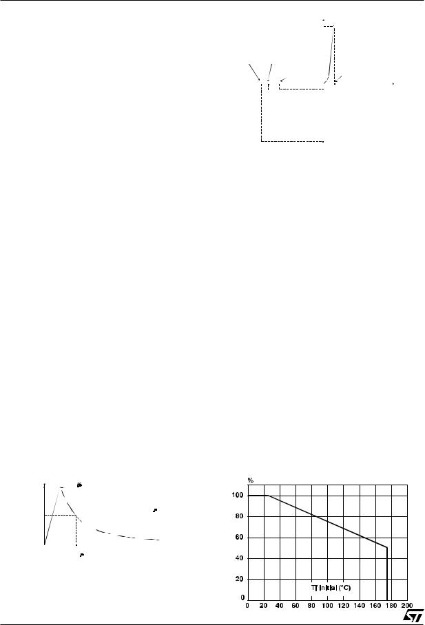
Fig. 1: Peak pulse power dissipation versus initial junction temperature (printed circuit board).
2/5
 Loading...