SGS Thomson Microelectronics BF259, BF258, BF257 Datasheet

BF257
BF258-BF259
HIGH VOLTAGE VIDEO AMPLIFIERS
DESCRIPTION
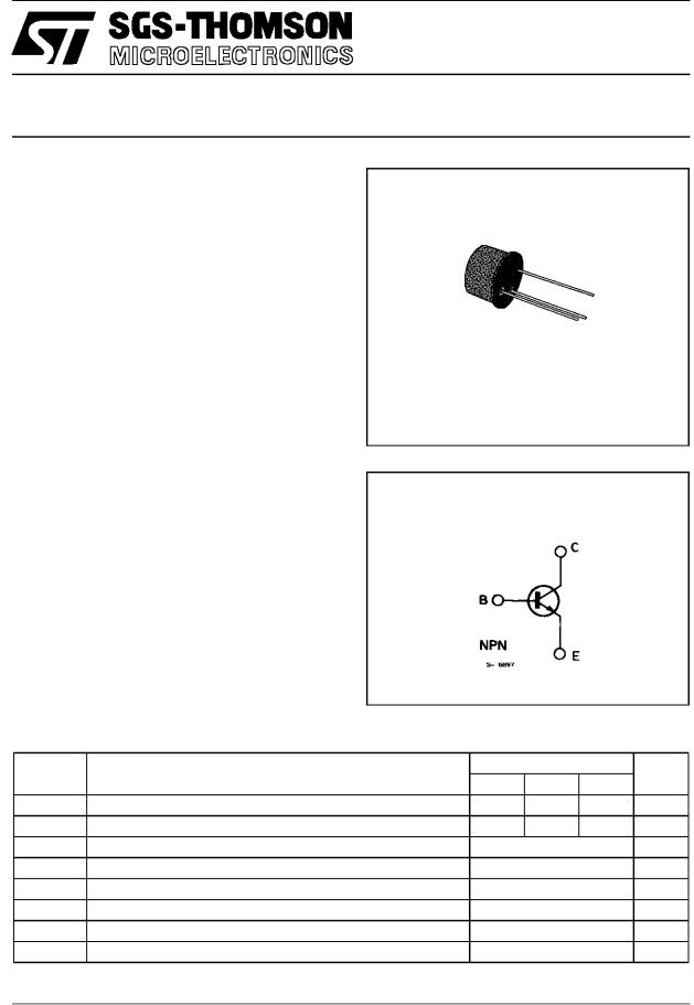
The BF257, BF258 and BF259 are silicon planar epitaxial NPN transistors in Jedec TO-39 metal case. They are particularly designed for videooutput stages in CTV and MTV sets, class A audio output stages and drivers for horizontal deflection circuits.
TO-39
INTERNAL SCHEMATIC DIAGRAM
ABSOLUTE MAXIMUM RATINGS
Symbol |
Parameter |
|
Value |
|
Unit |
|
BF 257 BF258 BF25 9 |
||||||
|
|
|
||||
VCBO |
Collector-base Voltage (IE = 0) |
160 |
250 |
300 |
V |
|
VCEO |
Collector-emitter Voltage (IB = 0) |
160 |
250 |
300 |
V |
|
VE BO |
Emitter-base Voltage (IC = 0) |
|
5 |
|
V |
|
IC |
Collector Current |
|
100 |
|
mA |
|
ICM |
Collector Peak Current |
|
200 |
|
mA |
|
Pt o t |
Total Power Dissipation at Tamb ≤ 50 °C |
|
5 |
|
W |
|
T s t g |
Storage Temperature |
|
± 55 to 200 |
|
°C |
|
T j |
Junction Temperature |
|
200 |
|
°C |
|
October 1988 |
1/5 |

BF257-BF258-BF259
THERMAL DATA
Rt h j- cas e |
Thermal Resistance Junction-case |
Max |
30 |
°C/W |
Rt h j-amb |
Thermal Resistance Junction-ambient |
Max |
175 |
°C/W |
ELECTRICAL CHARACTERISTICS (Tamb = 25 °C unless otherwise specified)
Symbol
ICB O
V(BR) CB O
V( BR) CEO *
V(BR) EB O
Parameter |
Test Conditions |
Min. |
Typ. Max. |
Unit |
|
Collector Cutoff Current |
for BF257 |
VCB = 100 V |
|
50 |
nA |
(I E = 0) |
for BF258 |
VCB = 200 V |
|
50 |
nA |
|
for BF259 |
VCB = 250 V |
|
50 |
nA |
Collector-base |
IC = 100 μA |
for BF257 |
160 |
|
V |
Breakdown Voltage |
for BF258 |
250 |
|
V |
|
(I E = 0) |
|
for BF259 |
300 |
|
V |
Collector-emitter |
|
for BF257 |
160 |
|
V |
Breakdown Voltage |
IC = 10 mA |
for BF258 |
250 |
|
V |
(I B = 0) |
|
for BF259 |
300 |
|
V |
Emittter-base |
IE = 100 μA |
|
|
|
|
Breakdown Voltage |
|
5 |
|
V |
|
(I C = 0)
VCE (s at )* Collector-emitter |
IC = 30 mA |
|
|
Saturation Voltage |
|
|
|
|
h FE* |
DC Current Gain |
IC = 30 mA |
fT |
Transition Frequency |
IC = 15 mA |
Cr e |
Reverse Capacitance |
IC = 0 |
|
|
f = 1 MHz |
* Pulsed : pulse duration = 300 μs, duty cycle = 1 %.
IB = 6 mA |
|
1 |
V |
VCE = 10 V |
25 |
|
|
VCE = 10 V |
90 |
|
MHz |
VCE = 30 V |
3 |
|
pF |
|
|
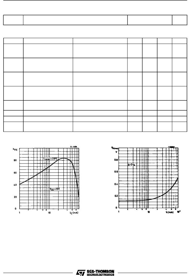
DC Current Gain.
2/5
 Loading...