


BYT60P-400
1/7
BYT60P-400
BYT260PIV-400 / BYT261PIV-400
May 2000 - Ed: 4D
FAST RECOVERY RECTIFIER DIODES
These rectifierdevicesaresuited for free-wheeling
function in converters and motor controlcircuits.
Packaged in ISOTOP or SOD93, they are
intended for use in Switch Mode Power Supplies.
DESCRIPTION
n VERY LOW REVERSE RECOVERY TIME
n VERY LOW SWITCHING LOSSES
n LOW NOISE TURN-OFF SWITCHING
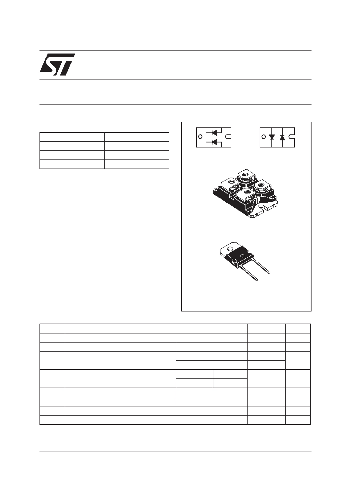
n INSULATED PACKAGE: ISOTOP
Insulation voltage: 2500 V
RMS
Capacitance = 45 pF
Inductance < 5nH
FEATURES ANDBENEFITS
Symbol Parameter Value Unit
V
RRM
Repetitive peakreverse voltage
400 V
I
FRM
Repetitive peakforward current tp=5 µs F=1kHz
1000 A
I
F(RMS)
RMS forward current ISOTOP
140 A
SOD93
100
I
F(AV)
Average forward current δ = 0.5 Tc = 70°C ISOTOP
60 A
Tc = 80°C SOD93
I
FSM
Surge non repetitive forward current
tp = 10 ms Sinusoidal
ISOTOP
600 A
SOD93
550
T
stg
Storage temperaturerange
- 40 to + 150 °C
Tj
Maximum operating junction temperature
150 °C
ABSOLUTE RATINGS (limiting values, per diode)
I
F(AV)
2 x 60 A
V
RRM
400 V
V
F
(max) 1.4 V
trr (max) 50 ns
MAIN PRODUCT CHARACTERISTICS
ISOTOP
TM
(Plastic)
K2 A2
A1K1
BYT261PIV-400
A2 K1
A1K2
BYT260PIV-400
TM: ISOTOP is aregistered trademark of STMicroelectronics.
K
A
SOD93
(Plastic)

BYT60P-400 / BYT260PIV-400 / BYT261PIV-400
2/7
Symbol Parameter Test Conditions Min. Typ. Max. Unit
V
F
*
Forward voltage drop Tj = 25°CI
F
=60A
1.5 V
Tj = 100°C
1.4
I
R
**
Reverse leakage cur-
rent
Tj = 25°CV
R
=V
RRM
60 µA
Tj = 100°C
6mA
Pulse test : * tp = 380 µs, δ <2%
** tp = 5 ms, δ <2%
STATIC ELECTRICAL CHARACTERISTICS (per diode)
Symbol Parameter Value Unit
R
th(j-c)
Junction to case ISOTOP Per diode
Total
0.8
0.45
°C/W
SOD93 Total
0.7
R
th(c)
Coupling
0.1 °C/W
When the diodes 1 and 2 are used simultaneously :
∆ Tj(diode 1)= P(diode) x R
th(j-c)
(Per diode) + P(diode 2) x R
th(c)
THERMAL RESISTANCES
To evaluatethe conduction losses use the following equation:
P = 1.1 x I
F(AV)
+0.0045 I
F
2
(RMS)
Symbol Test Conditions Min. Typ. Max. Unit
t
rr
Tj = 25°CI
F
=1A V
R
= 30V dI
F
/dt = - 15A/µs
100 ns
I
F
= 0.5A I
R
=1A I
rr
= 0.25A
50
RECOVERY CHARACTERISTICS (per diode)
Symbol Parameter Test Conditions Min. Typ. Max. Unit
t
IRM
Maximum reverse
recovery time
dI
F
/dt = - 240 A/µsV
CC
= 200 V
I
F
=60A
L
p
0.05 µH
Tj = 100°C
(see fig. 13)
75 ns
dI
F
/dt = - 480 A/µs
50
I
RM
Maximum reverse
recovery current
dI
F
/dt = - 240 A/µs
18 A
dI
F
/dt = - 480 A/µs
24
C=
V
V
RP
CC
Turn-off overvol t age
coeff icient
Tj = 100°CV
CC
= 120V I
F
=I
F(AV)
dI
F
/dt = - 60A/µsL
p
= 0.8µH
(see fig. 14)
3.3 4 /
TURN-OFF SWITCHING CHARACTERISTICS
BYT60P-400 / BYT260PIV-400 / BYT261PIV-400
3/7
0 1020304050607080
0
10
20
30
40
50
60
70
80
90
100
110
IF(av)(A)
PF(av)(W)
δ =1
δ= 0.5
δ = 0.2
δ= 0.1
δ = 0.05
T
δ
=tp/T tp
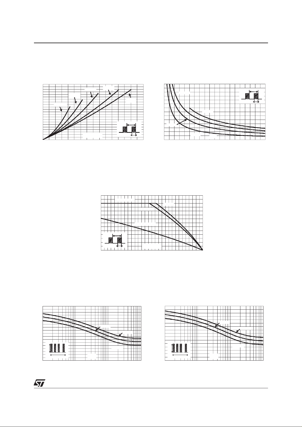
Fig. 1: Average forward power dissipation versus
average forward current (per diode, for ISOTOP).
0.0 0.1 0.2 0.3 0.4 0.5 0.6 0.7 0.8 0.9 1.0
0
50
100
150
200
250
300
350
IM(A)
δ
P=100W
P=75W
P=25W
P=50W
T
δ
=tp/T
tp
Fig. 2: Peak current versus form factor (per diode,
for ISOTOP).
0 25 50 75 100 125 150
0
10
20
30
40
50
60
70
Tamb(°C)
IF(av)(A)
Rth(j-a)=2.5°C/W
Rth(j-a)=Rth(j-c)
ISOTOP
SOD93
T
δ
=tp/T
tp
Fig. 3: Average forward current versus ambient
temperature (δ=0.5, per diode for ISOTOP).
1E-3 1E-2 1E-1 1E+0
0
50
100
150
200
250
300
350
400
450
t(s)
IM(A)
Tc=75°C
Tc=50°C
Tc=25°C
IM
t
δ=0.5
Fig. 4-1:Non repetitivesurge peak forward current
versus overload duration (SOD93).
1E-3 1E-2 1E-1 1E+0
0
50
100
150
200
250
300
350
400
Tc=75°C
Tc=50°C
Tc=25°C
t(s)
IM(A)
IM
t
δ=0.5
Fig. 4-2: Non repetitivesurge peak forward current
versus overload duration (per diode, for ISOTOP).
 Loading...