


SGS Thomson Microelectronics BTB24-800CW, BTB24-800BW, BTA25-800BW, BTA25-800B, BTA25-600CW Datasheet
...
|
|
BTA/BTB24, BTA25, BTA26 |
||
|
|
|
|
and T25 Series |
SNUBBERLESS & STANDARD |
|
|
25A TRIACS |
|
MAIN FEATURES: |
|
|
|
A2 |
Symbol |
Value |
Unit |
A2 |
A2 |
IT(RMS) |
25 |
A |
|
G |
VDRM/VRRM |
600 and 800 |
V |
|
A1 |
A1 |
A1 |
|||
|
|
|
A2 |
A2 |
IGT (Q ) |
35 to 50 |
mA |
G |
G |
|
|
|||
1 |
|
|
TO-220AB |
A2 TO-220AB |
|
|
|
||
DESCRIPTION |
|
|
Insulated |
(BTB24) |
|
|
(BTA24) |
|
|
|
|
|
|
|
Available either in through-hole of surface and T25 mount packages, the BTA/BTB24-25-26 triac series is suitable for general purpose AC power switching. They can be used as an ON/OFF function in applications such as static relays, heating regulation, water heaters, induction motor starting circuits...or for phase control operation in high power motor speed controllers, soft start circuits...The snubberless versions (BTA/BTB...W and T25 series) are specially recommended for use on inductive loads, thanks to their high commutation performances.
By using an internal ceramic pad, the BTA series provides voltage insulated tab (rated at 2500V RMS) complying with UL standards (File ref.: E81734).
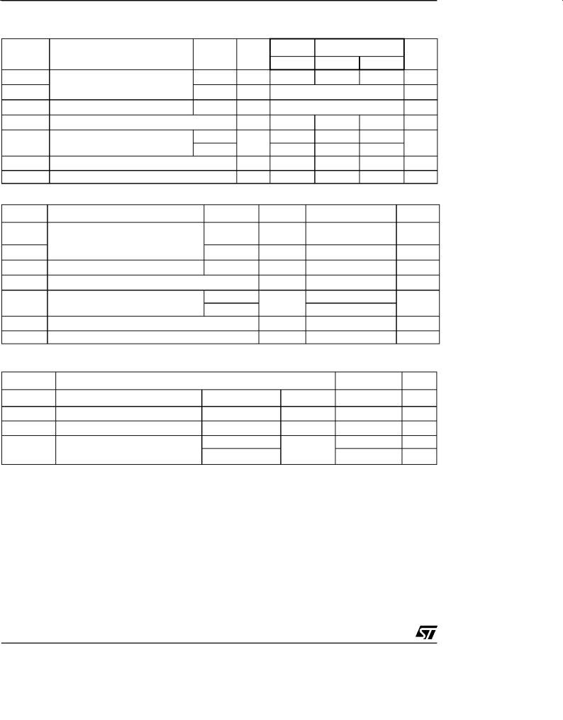
ABSOLUTE MAXIMUM RATINGS
A1 |
A2 |
|
G |
|
|
D2PAK |
|
|
A1 |
(T25G) |
|
|
|
|
|
G |
A2 |
|
|
|
|
A1 A2 |
G |
|
|
|
|
|
RD91 |
TOP3 |
|
|
(BTA25) |
Insulated |
|
|
|
(BTA26) |
|
Symbol
IT(RMS)
ITSM
I t
dI/dt
VDSM/VRSM
IGM
PG(AV)
Tstg
Tj
Parameter
RMS on-state current (full sine wave)
Non repetitive surge peak on-state current (full cycle, Tj initial = 25°C)
I t Value for fusing
Critical rate of rise of on-state current IG = 2 x IGT , tr ≤ 100 ns
Non repetitive surge peak off-state voltage
Peak gate current
Average gate power dissipation
Storage junction temperature range Operating junction temperature range
D PAK |
Tc = 100°C |
|
TO-220AB |
||
|
||
RD91 |
Tc = 90°C |
|
TOP3 Ins. |
||
|
||
TO-220AB Ins. |
Tc = 75°C |
|
F = 60 Hz |
t = 16.7 ms |
|
F = 50 Hz |
t = 20 ms |
|
tp = 10 ms |
||
F = 120 Hz |
Tj = 125°C |
|
tp = 10 ms |
Tj = 25°C |
|
tp = 20 μs |
Tj = 125°C |
|
|
Tj = 125°C |
|
September 2000 - Ed: 3
Value |
Unit |
|
|
A |
|
25 |
|
|
260 |
A |
|
250 |
|
|
450 |
A s |
|
50 |
A/μs |
|
VDRM/VRRM |
V |
|
+ 100 |
||
|
||
4 |
A |
|
1 |
W |
|
- 40 to + 150 |
°C |
|
- 40 to + 125 |
||
|
1/9
BTA/BTB24, BTA25, BTA26 and T25 Series
ELECTRICAL CHARACTERISTICS (Tj = 25°C, unless otherwise specified)
■ SNUBBERLESS (3 Quadrants) T25-G, BTA/BTB24...W, BTA25...W, BTA26...W
Symbol |
Test Conditions |
Quadrant |
T25 |
BTA/BTB |
Unit
IGT (1)
VGT
VGD
IH (2)
IL
dV/dt (2)
(dI/dt)c (2)
VD = 12 V |
RL = 33 Ω |
I - II - III |
|
I - II - III |
|||
|
|
||
VD = VDRM |
RL = 3.3 kΩ |
Tj = 125°C I - II - III |
|
IT = 500 mA |
|
|
|
IG = 1.2 IGT |
|
I - III |
|
|
|
II |
|
VD = 67 % VDRM gate open Tj = 125°C |
|||
Without snubber |
Tj = 125°C |
||
|
T2535 |
CW |
BW |
|
MAX. |
35 |
35 |
50 |
mA |
MAX. |
|
1.3 |
|
V |
MIN. |
|
0.2 |
|
V |
MAX. |
50 |
50 |
75 |
mA |
MAX. |
70 |
70 |
80 |
mA |
|
80 |
80 |
100 |
|
MIN. |
500 |
500 |
1000 |
V/μs |
MIN. |
13 |
13 |
22 |
A/ms |
■ STANDARD (4 Quadrants): BTA25...B, BTA26...B
Symbol |
|
Test Condit ions |
|
Quadrant |
|
Value |
Unit |
|
IGT (1) |
|
|
|
I - II - III |
MAX. |
50 |
mA |
|
|
|
VD = 12 V |
RL = 33 Ω |
|
IV |
100 |
|
|
VGT |
|
|
|
|||||
|
|
|
ALL |
MAX. |
1.3 |
V |
||
V |
GD |
VD = VDRM |
Ω |
° |
ALL |
MIN. |
0.2 |
V |
|
RL = 3.3 k Tj = 125 C |
|
|
|||||
IH (2) |
IT = 500 mA |
|
|
|
MAX. |
80 |
mA |
|
IL |
IG = 1.2 IGT |
|
|
I - III - IV |
MAX. |
70 |
mA |
|
|
|
|
|
|
II |
|
160 |
|
dV/dt (2) |
VD = 67 % VDRM gate open |
Tj = 125°C |
|
MIN. |
500 |
V/μs |
||
(dV/dt)c (2) |
(dI/dt)c = 13.3 A/ms |
Tj = 125°C |
|
MIN. |
10 |
V/μs |
||
STATIC CHARACTERISTICS
Symbol |
|
|
Test Conditions |
|
Value |
Unit |
|||
VTM (2) |
ITM = 35 A |
tp = 380 μs |
Tj = 25°C |
MAX. |
1.55 |
V |
|||
V |
to |
(2) |
Threshold voltage |
° |
MAX. |
0.85 |
V |
||
|
|
Tj = 125 C |
|||||||
R |
(2) |
Dynamic resistance |
° |
MAX. |
16 |
m |
Ω |
||
|
d |
|
Tj = 125 C |
|
|||||
IDRM |
VDRM = VRRM |
|
Tj = 25°C |
MAX. |
5 |
μA |
|||
IRRM |
|
|
Tj = 125°C |
3 |
mA |
||||
|
|
|
|||||||
Note 1: minimum IGT is guaranted at 5% of IGT max.
Note 2: for both polarities of A2 referenced to A1
2/9
BTA/BTB24, BTA25, BTA26 and T25 Series
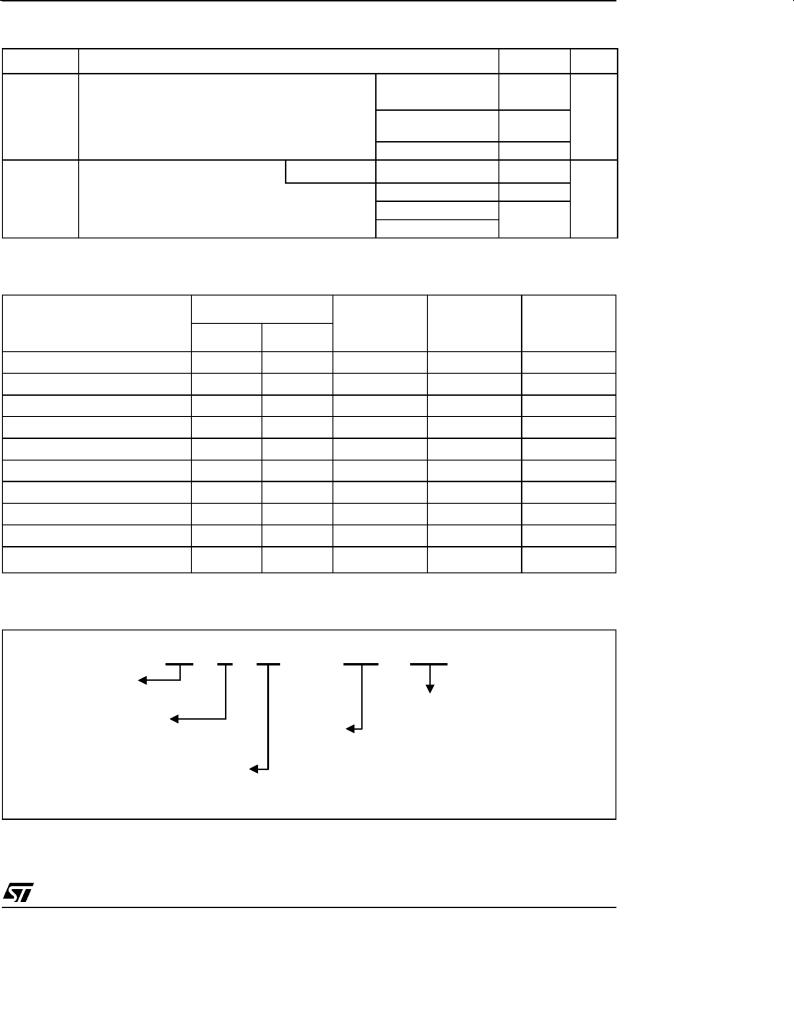
THERMAL RESISTANCES
Symbol |
|
Parameter |
|
Value |
Unit |
Rth(j-c) |
Junction to case (AC) |
|
D PAK |
0.8 |
°C/W |
|
|
|
TO-220AB |
|
|
|
|
|
|
|
|
|
|
|
RD91 (Insulated) |
1.1 |
|
|
|
|
TOP3 Insulated |
|
|
|
|
|
|
|
|
|
|
|
TO-220AB Insulated |
1.7 |
|
Rth(j-a) |
Junction to ambient |
S = 1 cm |
D PAK |
45 |
°C/W |
|
|
|
TOP3 Insulated |
50 |
|
|
|
|
TO-220AB |
60 |
|
|
|
|
TO-220AB Insulated |
|
|
|
|
|
|
|
|
S: Copper surface under tab |
|
|
|
|
|
PRODUCT SELECTOR
|
Voltage (xxx) |
|
|
|
||
Part Number |
600 |
V |
800 V |
Sensitivity |
Type |
Package |
|
|
|
|
|||
BTB24-xxxB |
X |
|
X |
50 mA |
Standard |
TO-220AB |
BTA/BTB24-xxxBW |
X |
|
X |
50 mA |
Snubberless |
TO-220AB |
BTA/BTB24-xxxCW |
X |
|
X |
35 mA |
Snubberless |
TO-220AB |
BTA25-xxxB |
X |
|
X |
50 mA |
Standard |
RD-91 |
BTA25-xxxBW |
X |
|
X |
50 mA |
Snubberless |
RD-91 |
BTA25-xxxCW |
X |
|
X |
35 mA |
Snubberless |
RD-91 |
BTA26-xxxB |
X |
|
X |
50 mA |
Standard |
TOP3 Ins. |
BTA26-xxxBW |
X |
|
X |
50 mA |
Snubberless |
TOP3 Ins. |
BTA26-xxxCW |
X |
|
X |
35 mA |
Snubberless |
TOP3 Ins. |
T2535-xxxG |
X |
|
X |
35 mA |
Snubberless |
D PAK |
BTB: Non insulated TO-220AB package
ORDERING INFORMATION
BT |
A 24 - |
600 |
BW |
TRIAC |
|
|
|
SERIES |
|
|
SENSITIVITY & TYPE |
|
|
|
|
INSULATION: |
|
|
B: 50mA STANDARD |
A: insulated |
VOLTAGE: |
|
BW: 50mA SNUBBERLESS |
B: non insulated |
600: 600V |
|
CW: 35mA SNUBBERLESS |
|
800: 800V |
|
|
CURRENT:
24:25A in TO-220AB
25:25A in Rd91
26:25A in TOP3
3/9
 Loading...