


DIGITAL LASER PRINTER
ML-2855 Series
ML-2855ND
SERVICE Manual 
DIGITAL LASER PRINTER |
|
The keynote of Product |
|
Smallest Duplex Built-in |
|
|
||
|
Mono Laser Printer (Low Noise) |
|
|
- 28ppm(A4) / 30ppm(Ltr) |
|
|
- PCL6, PS3, 1,200x1,200dpi |
|
|
- 400MHz processor |
|
|
- USB 2.0, N/W |
|
|
- 64MB (Max.192MB) |
|
|
- 2K Standard, 5K High Yield |
|
|
- Paper Input: 250sh CST + 50sh MP |
|
|
- Standard Duplex Printing |
|
|
- Options: 250sh SCF |
|
ML-2855ND |
|
|
|
|
|
|
|
|

Contents
1.Precautions
1.1Safety Warning••••••••••••••••••••••••••••••••••••••••••••••••••••••••1-1
1.2Caution for safety•••••••••••••••••••••••••••••••••••••••••••••••••••••1-2
1.3ESD Precautions••••••••••••••••••••••••••••••••••••••••••••••••••••••1-5
2.Product spec and feature
2.1Product Specifications•••••••••••••••••••••••••••••••••••••••••••••••2-1
2.1.1Product Overview••••••••••••••••••••••••••••••••••••••••••••••••2-1
2.1.2Specifications•••••••••••••••••••••••••••••••••••••••••••••••••••••2-1
2.1.3Model Comparison Table•••••••••••••••••••••••••••••••••••••••2-6
2.2Summary of Product••••••••••••••••••••••••••••••••••••••••••••••••••2-8
2.2.1Printer Components•••••••••••••••••••••••••••••••••••••••••••••2-8
2.2.2System Layout•••••••••••••••••••••••••••••••••••••••••••••••••2-10
2.2.3Engine H/W Specifications••••••••••••••••••••••••••••••••••2-15
2.2.4S/W Descriptions••••••••••••••••••••••••••••••••••••••••••••••2-25
3.Disassembly and Reassembly
3.1Disassembly and Reassemblyons on Disassembly••••••••••••3-1
3.1.1Screws used in the printer••••••••••••••••••••••••••••••••••••••3-2
3.2General Disassembly•••••••••••••••••••••••••••••••••••••••••••••••••3-3
3.2.1Cover Unit••••••••••••••••••••••••••••••••••••••••••••••••••••••••••3-3
3.2.2Fuser Unit •••••••••••••••••••••••••••••••••••••••••••••••••••••••••3-5
3.2.3LSU Unit •••••••••••••••••••••••••••••••••••••••••••••••••••••••••••3-6
3.2.4Main PBA/ SMPS/ HVPS•••••••••••••••••••••••••••••••••••••••3-7
3.2.5Transfer Roller••••••••••••••••••••••••••••••••••••••••••••••••••••3-8
3.2.6Drive Unit••••••••••••••••••••••••••••••••••••••••••••••••••••••••••3-9
3.2.7Holder-Pad•••••••••••••••••••••••••••••••••••••••••••••••••••••••••3-9
3.2.8OPE PBA•••••••••••••••••••••••••••••••••••••••••••••••••••••••••3-10

Continued
4.Alignment & Troubleshooting
4.1Alignment and Adjustments•••••••••••••••••••••••••••••••••••••••••4-1
4.1.1Control Panel overview•••••••••••••••••••••••••••••••••••••••••4-1
4.1.2Understanding The Status LED•••••••••••••••••••••••••••••••4-2
4.1.3Clearing JAM•••••••••••••••••••••••••••••••••••••••••••••••••••••4-3
4.1.4Menu Map•••••••••••••••••••••••••••••••••••••••••••••••••••••••••4-8
4.1.5Printing a test page••••••••••••••••••••••••••••••••••••••••••••4-10
4.1.6EDC Mode••••••••••••••••••••••••••••••••••••••••••••••••••••••4-12
4.1.7Abnormal Image Printing and Defective Roller••••••••••4-15
4.1.8Error Message•••••••••••••••••••••••••••••••••••••••••••••••••4-16
4.2Troubleshooting•••••••••••••••••••••••••••••••••••••••••••••••••••••4-18
4.2.1Procedure of Checking the Symptoms••••••••••••••••••••4-18
4.2.2The cause and solution of Bad image•••••••••••••••••••••4-19
4.2.3The cause and solution of the bad discharge••••••••••••4-34
4.2.4The cause and solution of the malfunction•••••••••••••••4-42
4.2.5The cause and solutions of
bad environment of the software•••••••••••••••••••••••••••4-51
5.System Diagram
5.1Block Diagram•••••••••••••••••••••••••••••••••••••••••••••••••••••••••5-1
5.2Connection Diagram••••••••••••••••••••••••••••••••••••••••••••••••••5-2
6.Reference Information
6.1Tool for Troubleshooting•••••••••••••••••••••••••••••••••••••••••••••6-1
6.2Acronyms and Abbreviations••••••••••••••••••••••••••••••••••••••••6-2
6.2.1Acronyms••••••••••••••••••••••••••••••••••••••••••••••••••••••••••6-2
6.2.2Service Parts•••••••••••••••••••••••••••••••••••••••••••••••••••••6-4
6.3The Sample Pattern for the Test•••••••••••••••••••••••••••••••••••6-8

Continued
6.4 Selecting a location•••••••••••••••••••••••••••••••••••••••••••••••••••6-9
Parts Catalog
Power Cord•••••••••••••••••••••••••••••••••••••••••••••••••••••••••••••••••••• 2 Thumbnail ••••••••••••••••••••••••••••••••••••••••••••••••••••••••••••••••••••• 3
1.Main••••••••••••••••••••••••••••••••••••••••••••••••••••••••••••••••••••••••• 4
2.Top Cover••••••••••••••••••••••••••••••••••••••••••••••••••••••••••••••••••• 6
3.Cover Ass’y••••••••••••••••••••••••••••••••••••••••••••••••••••••••••••••••• 8
4.Front Cover••••••••••••••••••••••••••••••••••••••••••••••••••••••••••••••••10
5.Rear Cover•••••••••••••••••••••••••••••••••••••••••••••••••••••••••••••••••12
6.Frame•••••••••••••••••••••••••••••••••••••••••••••••••••••••••••••••••••••••14
7.Main Drive••••••••••••••••••••••••••••••••••••••••••••••••••••••••••••••••••18
8.Rear Guide•••••••••••••••••••••••••••••••••••••••••••••••••••••••••••••••••20
9.Fuser••••••••••••••••••••••••••••••••••••••••••••••••••••••••••••••••••••••••22
10.Duplex Unit ••••••••••••••••••••••••••••••••••••••••••••••••••••••••••••••24
11.Cassette ••••••••••••••••••••••••••••••••••••••••••••••••••••••••••••••••••26
12.SCF •••••••••••••••••••••••••••••••••••••••••••••••••••••••••••••••••••••••28

Precautions
1. Precautions
In order to prevent accidents and to prevent damage to the equipment please read the precautions listed below carefully before servicing the printer and follow them closely.
1.1 Safety Warning
(1)Only to be serviced by appropriately qualified service engineers.
High voltages and lasers inside this product are dangerous. This printer should only be serviced by a suitably trained and qualified service engineer.
(2)Use only Samsung replacement parts
There are no user serviceable parts inside the printer. Do not make any unauthorized changes or additions to the printer, these could cause the printer to malfunction and create electric shock or fire hazards.
(3)Laser Safety Statement
The Printer is certified in the U.S. to conform to the requirements of DHHS 21 CFR, chapter 1 Subchapter J for Class 1(1) laser products, and elsewhere, it is certified as a Class I laser product con-forming to the requirements of IEC 825. Class I laser products are not considered to be hazardous. The laser system and printer are designed so there is never any human access to laser radiation above a Class I level during normal operation, user maintenance, or prescribed service condition.
Warning >> Never operate or service the printer with the protective cover removed from Laser/
Scanner assembly. The reflected beam, although invisible, can damage your eyes. When using this product, these basic safety pre-cautions should always be followed to reduce risk of fire, electric shock, and injury to persons.
Service Manual |
1-1 |
Samsung Electronics |
|

Precautions
1.2 Caution for safety
1.2.1 Toxic material
This product contains toxic materials that could cause illness if ingested.
(1)If the LCD control panel is damaged it is possible for the liquid inside to leak. This liquid is toxic. Contact with the skin should be avoided, wash any splashes from eyes or skin immediately and contact your doctor. If the liquid gets into the mouth or is swallowed see a doctor immediately.
(2)Please keep Drum cartridge and Toner Cartridge away from children. The toner powder contained in the Drum cartridge and Toner Cartridge may be harmful and if swallowed you should contact a doctor.
1.2.2 Electric Shock and Fire Safety Precautions
Failure to follow the following instructions could cause electric shock or potentially cause a fire.
(1)Use only the correct voltage, failure to do so could damage the printer and potentially cause a fire or electric shock.
(2)Use only the power cable supplied with the printer. Use of an incorrectly specified cable could cause the cable to overheat and potentially cause a fire.
(3)Do not overload the power socket, this could lead to overheating of the cables inside the wall and could lead to a fire.
(4)Do not allow water or other liquids to spill into the printer, this can cause electric shock. Do not allow paper clips, pins or other foreign objects to fall into the printer these could cause a short circuit leading to an electric shock or fire hazard.
(5)Never touch the plugs on either end of the power cable with wet hands, this can cause electric shock.
When servicing the printer remove the power plug from the wall socket.
(6)Use caution when inserting or removing the power connector. The power connector must be inserted completely otherwise a poor contact could cause overheating possibly leading to a fire. When removing the power connector grip it firmly and pull.
(7)Take care of the power cable. Do not allow it to become twisted, bent sharply round corners or other wise damaged. Do not place objects on top of the power cable. If the power cable is damaged it could overheat and cause a fire or exposed cables could cause an electric shock. Replace a damaged power cable immediately, do not reuse or repair the damaged cable. Some chemicals can attack the coating on the power cable, weakening the cover or exposing cables causing fire and shock risks.
(8)Ensure that the power sockets and plugs are not cracked or broken in any way. Any such defects should be repaired immediately. Take care not to cut or damage the power cable or plugs when moving the machine.
(9)Use caution during thunder or lightening storms. Samsung recommend that this machine be disconnected from the power source when such weather conditions are expected. Do not touch the machine or the power cord if it is still connected to the wall socket in these weather conditions.
(10)Avoid damp or dusty areas, install the printer in a clean well ventilated location. Do not position the machine near a humidifier. Damp and dust build up inside the machine can lead to overheating and cause a fire.
(11)Do not position the printer in direct sunlight. This will cause the temperature inside the printer to rise possibly leading to the printer failing to work properly and in extreme conditions could lead to a fire.
(12)Do not insert any metal objects into the machine through the ventilator fan or other part of the casing, it could make contact with a high voltage conductor inside the machine and cause an electric shock.
Service Manual |
1-2 |
Samsung Electronics |
|

Precautions
1.2.3 Handling Precautions
The following instructions are for your own personal safety, to avoid injury and so as not to damage the printer
(1)Ensure the printer is installed on a level surface, capable of supporting its weight. Failure to do so could cause the printer to tip or fall.
(2)The printer contains many rollers, gears and fans. Take great care to ensure that you do not catch your fingers, hair or clothing in any of these rotating devices.
(3)Do not place any small metal objects, containers of water, chemicals or other liquids close to the printer which if spilled could get into the machine and cause damage or a shock or fire hazard.
(4)Do not install the machine in areas with high dust or moisture levels, beside on open window or close to a humidifier or heater. Damage could be caused to the printer in such areas.
(5)Do not place candles, burning cigarettes, etc on the printer, These could cause a fire.
1.2.4 Assembly / Disassembly Precautions
Replace parts carefully, always use Samsung parts. Take care to note the exact location of parts and also cable routing before dismantling any part of the machine. Ensure all parts and cables are replaced correctly. Please carry out the following procedures before dismantling the printer or replacing any parts.
(1)Check the contents of the machine memory and make a note of any user settings. These will be erased if the mainboard or network card is replaced.
(2)Ensure that power is disconnected before servicing or replacing any electrical parts.
(3)Disconnect printer interface cables and power cables.
(4)Only use approved spare parts. Ensure that part number, product name, any voltage, current or temperature rating are correct.
(5)When removing or re-fitting any parts do not use excessive force, especially when fitting screws into plastic.
(6)Take care not to drop any small parts into the machine.
(7)Handling of the OPC Drum
-The OPC Drum can be irreparably damaged if it exposed to light.
Take care not to expose the OPC Drum either to direct sunlight or to fluorescent or incandescent room lighting. Exposure for as little as 5 mins can damage the surface? photoconductive properties and will result in print quality degradation. Take extra care when servicing the printer. Remove the OPC Drum and store it in a black bag or other lightproof container. Take care when working with the covers(especially the top cover) open as light is admitted to the OPC area and can damage the OPC
Drum.
-Take care not to scratch the green surface of OPC Drum Unit.
If the green surface of the Drum Cartridge is scratched or touched the print quality will be compromised.
Service Manual |
1-3 |
Samsung Electronics |
|

Precautions
1.2.5 Disregarding this warning may cause bodily injury
(1)Be careful with the high temperature part.
The fuser unit works at a high temperature. Use caution when working on the printer. Wait for the fuser to cool down before disassembly.
(2)Do not put finger or hair into the rotating parts.
When operating a printer, do not put hand or hair into the rotating parts (Paper feeding entrance, motor, fan, etc.). If do, you can get harm.
(3)When you move the printer.
This printer weighs 9.26kg (20.41 lbs) including toner cartridge and cassette. Use safe lifting and handling techniques. Use the lifting handles located on each side of the machine. Back injury could be caused if you do not lift carefully.
(4)Ensure the printer is installed safely.
The printer weighs 9.26kg (20.41 lbs), ensure the printer is installed on a level surface, capable of supporting its weight. Failure to do so could cause the printer to tip or fall possibly causing personal injury or damaging the printer.
(5)Do not install the printer on a sloping or unstable surface. After installation, double check that the printer is stable.
Service Manual |
1-4 |
Samsung Electronics |
|

Precautions
1.3 ESD Precautions
Certain semiconductor devices can be easily damaged by static electricity. Such components are commonly called “Electrostatically Sensitive (ES) Devices” or ESDs. Examples of typical ESDs are: integrated circuits, some field effect transistors, and semiconductor “chip” components.
The techniques outlined below should be followed to help reduce the incidence of component damage caused by static electricity.
Caution >>Be sure no power is applied to the chassis or circuit, and observe all other safety precautions.
1.Immediately before handling a semiconductor component or semiconductor-equipped assembly, drain off any electrostatic charge on your body by touching a known earth ground. Alternatively, employ a
commercially available wrist strap device, which should be removed for your personal safety reasons prior to applying power to the unit under test.
2.After removing an electrical assembly equipped with ESDs, place the assembly on a conductive surface, such as aluminum or copper foil, or conductive foam, to prevent electrostatic charge buildup in the vicinity of the assembly.
3.Use only a grounded tip soldering iron to solder or desolder ESDs.
4.Use only an “anti-static” solder removal device. Some solder removal devices not classified as “anti-static” can generate electrical charges sufficient to damage ESDs.
5.Do not use Freon-propelled chemicals. When sprayed, these can generate electrical charges sufficient to damage ESDs.
6.Do not remove a replacement ESD from its protective packaging until immediately before installing it. Most replacement ESDs are packaged with all leads shorted together by conductive foam, aluminum foil, or a comparable conductive material.
7.Immediately before removing the protective shorting material from the leads of a replacement ESD, touch the protective material to the chassis or circuit assembly into which the device will be installed.
8.Maintain continuous electrical contact between the ESD and the assembly into which it will be installed, until completely plugged or soldered into the circuit.
9.Minimize bodily motions when handling unpackaged replacement ESDs. Normal motions, such as the brushing together of clothing fabric and lifting one’s foot from a carpeted floor, can generate static electricity sufficient to damage an ESD.
Service Manual |
1-5 |
Samsung Electronics |
|

Product spec and feature
2. Product spec and feature
2.1 Product Specifications
2.1.1 Product Overview
•28ppm(A4) / 30ppm(Ltr)
•PCL6, PS3, 1,200x1,200dpi
•400MHz processor
•USB 2.0, N/W
•64MB(Max.192MB)
•2K Standard, 5K High Yield
•Paper Input: 250 CST + 50 MP
•Standard Duplex Printing (World Smallest)
•Options:
-250 sh SCF
2.1.2 Specifications
• Product Specifications are subject to change without notice. See below for product specifications.
2.1.2.1 General Print Engine
|
Items |
ML-2855ND |
|
Engine Speed |
|
Simplex |
Up to 28 ppm in A4 (30 ppm in Letter) |
|
|
|
|
|
|
Duplex |
Up to 14 ipm in A4 (14.5 ipm in Letter) |
|
|
|
|
Warmup time |
|
From Sleep |
15 sec |
|
|
|
|
FPOT |
|
From Ready |
8.5 sec |
|
|
|
|
|
|
From Sleep |
less than 23.5 sec |
|
|
|
|
Resolution |
|
- |
Up to 1,200 x 1,200 dpi effective output |
|
|
|
|
Service Manual |
2-1 |
Samsung Electronics |
|
Product spec and feature
2.1.2.2 Controller & S/W
|
|
Items |
ML-2855ND |
|
|
|
Processor |
|
|
Samsung 400 MHz |
|
|
|
|
|
|
|
|
Memory |
|
Std. |
64MB |
|
|
|
|
|
|
|
|
|
|
Max. |
192MB (128 MB Option Memory) |
|
|
|
|
|
|
|
|
Printer Languages |
|
- |
PostScript3, PCL6, SPL, IBM ProPrinter, EPSON |
|
|
|
|
|
|
|
|
Fonts |
|
- |
45 scalable, 1 bitmap, 136 PostScript3 fonts |
|
|
|
|
|
|
|
|
Driver |
|
Default Driver |
SPL |
|
|
|
|
|
|
|
|
|
|
Install |
SPL, PCL6, PS3 |
|
|
|
|
|
|
|
|
|
|
Supporting OS |
Windows 2000/XP(32/64bits)/Vista(32/64bits)/2003 Server(32/64bits) |
|
|
|
|
|
|
|
|
|
|
|
Various Linux OS: |
|
|
|
|
|
- Red Hat 8~9, |
|
|
|
|
|
- Fedora Core 1~4 |
|
|
|
|
|
- Mandrake 9.2~10.1 |
|
|
|
|
|
- SuSE 8.2~9.2 |
|
|
|
|
|
|
|
|
|
|
|
Mac OS 8.6~9.2 / 10.1~10.4 |
|
|
|
|
|
|
|
|
|
|
WHQL |
Windows 2000, XP, 2003 Server, Vista(32/64bits) |
|
|
|
|
|
|
|
|
|
|
Compatibility |
SPL & PCL6 : Win 2000/XP(32/64bits)/2003 server/Vista(32/64bits) |
|
|
|
|
|
PS3 : Win 2000/XP(32/64bits)/Vista(32/64bits)/2003 PPD, |
|
|
|
|
|
Mac PPD, Linux PPD |
|
|
|
|
|
|
|
|
Wired Network |
|
Protocol |
SPX/IPX, TCP/IP, Ethertalk, SNMP, HTTP 1.1 |
|
|
|
|
|
|
|
|
|
|
Supporting OS |
Windows NT4.0/2000/XP(32/64bits)/2003 Server/Vista(32/64bits) |
|
|
|
|
|
NetWare 5.x, 6.x |
|
|
|
|
|
Mac OS 8.6~9.2, 10.1~10.4 |
|
|
|
|
|
Various Linux OS including Red Hat 8~9, Fedora Core 1~4, |
|
|
|
|
|
Mandrake 9.2~10.1, and SuSE 8.2~9.2Unix HP-UX |
|
|
|
|
|
|
|
|
Wireless Network |
|
Protocol |
N/A |
|
|
|
|
|
|
|
|
|
|
Supporting OS |
N/A |
|
|
|
|
|
|
|
|
Application |
|
Smart Panel |
SmartPanel for Windows/ Macintosh/LINUX |
|
|
|
|
|
|
|
|
|
|
Printer Setting |
PSU for Windows/ Macintosh/LINUX |
|
|
|
|
|
|
|
|
|
|
Network Management |
SyncThru Web Admin Service 4.0 |
|
|
|
|
|
|
|
|
|
|
IP Setting |
SetIP |
|
|
|
|
|
|
|
|
Interface |
|
|
|
|
|
Parallel |
|
- |
N/A |
|
|
|
|
|
|
|
|
USB |
|
- |
Hi-Speed USB 2.0 |
|
|
|
|
|
|
|
|
Wired Network |
|
- |
Ethernet 10/100 Base TX (Internal) |
|
|
|
|
|
|
|
|
Wireless Network |
|
- |
N/A |
|
|
|
|
|
|
|
|
User Interface |
|
|
|
|
|
LCD |
|
- |
2 Line-LCD |
|
|
|
|
|
|
|
|
LED |
|
- |
1-Status LED |
|
|
|
|
|
|
|
|
Key |
|
- |
2 Keys (Main, Stop) |
|
|
|
|
|
|
|
Service Manual |
|
|
2-2 |
Samsung Electronics |
|
|
|
|
|||

Product spec and feature
2.1.2.3 Paper Handling
|
|
Items |
ML-2855ND |
|
|
|
Standard Capacity |
|
- |
250-sheet Cassette Tray, 1-sheet Multi Purpose Tray @80g/ |
|
|
|
|
|
|
|
|
Max. Capacity |
|
- |
550 sheets @ 80g/ |
|
|
|
|
|
|
|
|
Printing |
|
Max. Size |
216 x 356 mm (8.5" x 14") |
|
|
|
|
|
|
|
|
|
|
Min. Size |
76 x 127 mm (3.0" x 5.0") |
|
|
|
|
|
|
|
|
Multi-purpose tray |
|
|
||
|
Capacity |
|
Plain Paper |
50 sheets @ 80g/ |
|
|
|
|
|
|
|
|
|
|
Envelope |
5 sheets @75g/ |
|
|
|
|
|
|
|
|
Media sizes |
|
- |
A4, A5, A6, Letter, Legal, Folio, Oficio, Executive,ISO B5, JIS B5, |
|
|
|
|
|
3”x5”, Monarch, No.10, DL, C5, C6 |
|
|
|
|
|
|
|
|
Media type |
|
- |
Plain Paper, Transparency, Envelope, Labels, Post Card, Card stock |
|
|
|
|
|
|
|
|
Media weight |
|
- |
16~43lb (60 to 163g/ ) |
|
|
|
|
|
|
|
|
Sensing |
|
- |
Paper empty sensor |
|
|
|
|
|
|
|
|
Standard Cassette Tray |
|
|
||
|
Capacity |
|
- |
250 sheets @ 80g/ |
|
|
|
|
|
|
|
|
Media sizes |
|
- |
A4, A5, Letter, Legal, Executive, Folio, Oficio, ISO B5, JIS B5 |
|
|
|
|
|
|
|
|
Media types |
|
- |
Plain paper |
|
|
|
|
|
|
|
|
Media weight |
|
- |
16~28lb (60 to 105g/ ) |
|
|
|
|
|
|
|
|
Sensing |
|
- |
Paper empty sensor |
|
|
|
|
|
|
|
|
Optional Cassette Tray |
|
|
||
|
Capacity |
|
- |
250 sheets @ 80g/ |
|
|
|
|
|
|
|
|
Media sizes |
|
- |
A4, A5, Letter, Legal, Executive, Folio, Oficio, ISO B5, JIS B5 |
|
|
|
|
|
|
|
|
Media types |
|
- |
Plain paper |
|
|
|
|
|
|
|
|
Media weight |
|
- |
16~28lb (60 to 105g/ ) |
|
|
|
|
|
|
|
|
Sensing |
|
- |
Paper empty sensor |
|
|
|
|
|
|
|
|
Output Stacking |
|
|
|
|
|
Capacity |
|
Face-Down |
150 sheets @ 75g/ |
|
|
|
|
|
(Baseline paper : samsung premium/Xerox 4200) NN condition |
|
|
|
|
|
|
|
|
|
|
Face-Up |
N/A |
|
|
|
|
|
|
|
|
Output Full sensing |
|
- |
N/A |
|
|
|
|
|
|
|
|
Duplex |
|
|
|
|
|
Supporting |
|
- |
Built-in |
|
|
|
|
|
|
|
|
Media sizes |
|
- |
A4, Letter, Legal, Folio, Oficio |
|
|
|
|
|
|
|
|
Media types |
|
- |
Plain Paper |
|
|
|
|
|
|
|
|
Media weight |
|
- |
20~24lb (75 to 90g/ ) |
|
|
|
|
|
|
|
|
Printable Area |
|
|
|
|
|
Non-Printable Area |
|
Envelope |
10mm(0.4") from edge(Top, Bottom, Left, Right) |
|
|
|
|
|
|
|
|
|
|
Other Media |
4mm(0.16") from edge(Top, Bottom, Left, Right) |
|
|
|
|
|
|
|
Service Manual |
|
|
2-3 |
Samsung Electronics |
|
|
|
|
|||

Product spec and feature
2.1.2.4 Consumables
|
Items |
ML-2855ND |
|
Toner |
|
Black |
Standard: Average Cartridge Yield 2K standard pages. |
|
|
|
High Yield: Average cartridge Yield 5K standard pages. |
|
|
|
Declared cartridge yield in accordance with ISO/IEC 19752. |
|
|
|
|
|
|
Key |
Electronic key(CRUM) Only |
|
|
|
|
|
|
Life detect |
Toner gauge sensor by dot count |
|
|
|
|
Drum |
|
Yield |
N/A |
|
|
|
|
2.1.2.5 Reliability & Service
|
Items |
ML-2855ND |
|
Max. Monthly Duty |
|
- |
30,000 sheets |
|
|
|
|
MPBF |
|
- |
35,000 sheets |
|
|
|
|
MTTR |
|
- |
30 min. |
|
|
|
|
SET Life Cycle |
|
- |
100,000 sheets or 5 years (whichever comes first) |
|
|
|
|
RDS |
|
Comm. Mode |
Yes |
|
|
|
|
|
|
Operation |
Yes |
|
|
|
|
2.1.2.6 Environment
Items |
ML-2855ND |
|
Operating |
Temperature |
10C to 32C |
|
|
|
Environment |
Humidity |
20% to 80% |
|
|
|
Acoustic Noise |
Printing |
Less than 50dBA |
|
|
|
Level(Sound |
Standby |
Less than 26.0 dBA |
|
|
|
Power/Pressure) |
Sleep |
Back Ground Level |
|
|
|
Power Consumption |
Ready |
Less than 60W |
|
|
|
|
AVG. |
Less than 400W |
|
|
|
|
Sleep / Power Off |
Less than 8W / Less than 0.4W (Conformity to EPA) |
|
|
|
Dimension |
SET |
391 x 370 x 235 mm |
(W x D x H) |
|
(15.4 x 14.6 x 9.3 inches) without optional tray |
|
|
|
Weight |
SET |
9.26Kg (20.41 lbs) |
(with Consumables) |
|
|
|
|
|
Service Manual |
2-4 |
Samsung Electronics |
|
Product spec and feature
2.1.2.7 Packing & Accessory
|
Items |
ML-2855ND |
|
In-Box |
|
- |
Driver & Network Install CD-ROM |
|
|
|
Power Cable |
|
|
|
USB Cable (CIS/China/Korea/India) |
|
|
|
Quick Install Guide |
|
|
|
Warranty Registration Card |
|
|
|
User’s Manual (PDF File) |
|
|
|
|
2.1.2.8 Options
|
Items |
ML-2855ND |
|
Memory |
|
- |
Factory option (128MB) |
|
|
|
|
Second Cassette |
|
- |
250-sheet Cassette Tray |
|
|
|
|
Wired Network |
|
- |
N/A (Built-in) |
|
|
|
|
Wireless Network |
|
- |
N/A |
|
|
|
|
Hard Disk |
|
- |
N/A |
|
|
|
|
Duplex Unit |
|
- |
Standard |
|
|
|
|
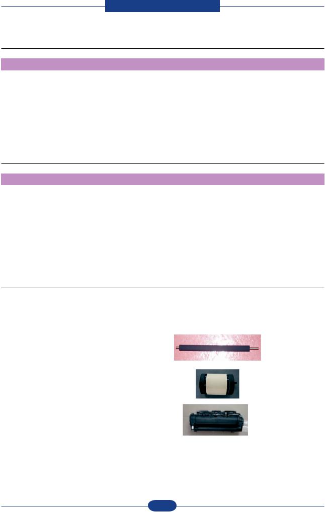
2.1.2.9 Reliability & Service
* Periodic Replacing Parts
NoNo. . |
Parts Parts |
CodeCode |
Fig. |
Yield (pages) |
|
|
|
|
|
1 |
Transfer Roller |
JC66-01218A |
|
50,000 |
|
|
|
|
|
2 |
Pick-up Roller |
JC97-03062A |
|
50,000 |
|
|
|
|
|
3 |
Fuser Unit |
JC96-04717A(220V) |
|
50,000 |
JC96-04718A(110V) |
|
|||
|
|
|
|
|
|
|
|
|
|
Service Manual |
2-5 |
Samsung Electronics |
|
Product spec and feature
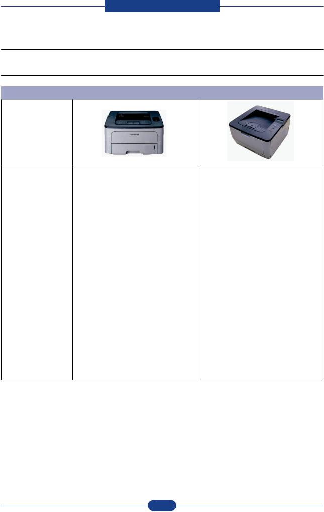
2.1.3 Model Comparison Table
2.1.3.1 SEC Model
|
Plover (ML-2851ND) |
Plover-P(ML-2855ND) |
|
|
|
Image
Speed(A4) |
28 ppm (A4) |
28 ppm (A4) |
|
|
|
|
|
Resolution |
1,200 x 1,200 dpi |
1,200 x 1,200 dpi |
|
|
|
|
|
Warm-up |
15 sec |
15 sec |
|
|
|
|
|
FPOT |
8.5 sec (from ready) |
8.5 sec (from ready) |
|
15.5 sec (from sleep) |
15.5 sec (from sleep) |
||
|
|||
|
|
|
|
Memory |
32 MB (Max.160 MB) |
64 MB (Max.192 MB) |
|
|
|
|
|
Interface |
N/W, USB 2.0 |
N/W, USB 2.0 |
|
|
|
|
|
User Interface |
2 LED, 1Key |
2-Line LCD + New Design key |
|
|
|
|
|
Duplex |
Standard |
Standard |
|
|
|
|
|
Paper Capacity |
250 CST, 1 MP |
250 CST, 50 MP |
|
250 SCF x 1 (Max. 501 sh) |
250 SCF x 1 (Max. 550 sh) |
||
|
|||
|
|
|
|
Toner |
STD : 2K |
STD : 2K |
|
Max : 5K |
Max : 5K |
||
|
|||
|
|
|
|
Max.Duty |
50,000 |
50,000 |
|
|
|
|
|
Set life |
100,000 |
100,000 |
|
|
|
|
|
Max.Duty |
50,000 |
50,000 |
|
|
|
|
|
Set life |
100,000 |
100,000 |
Service Manual |
2-6 |
Samsung Electronics |
|

Product spec and feature
2.1.3.2 Competitor Model
|
Samsung |
Brother |
Lexmark |
|
ML-2855ND |
HL-5240 |
E250D |
|
|
|
|
Image
Print Speed |
28 ppm/A4 |
30 ppm/Ltr |
30 ppm/Ltr |
|
|
|
|
|
|
Resolution |
1,200 dpi class |
1,200 dpi class |
600 x 600 dpi |
|
|
|
|
|
|
Processor |
400 MHz |
264 MHz |
300 MHz |
|
|
|
|
|
|
Memory (Max.) |
64 MB (192 MB) |
16 MB (16 MB) |
64 MB (576 MB) |
|
|
|
|
|
|
Emulation |
PCL6, PS3 |
PCL6, PS3 |
PCL6, PS3 |
|
|
|
|
|
|
Interface |
USB 2.0, N/W |
USB 2.0, N/W |
USB 2.0, N/W |
|
|
|
|
|
|
Paper Input |
250 CST |
250 OT |
250 CST |
|
|
|
|
|
|
FPOT (C/M) |
30 sec/8.5 sec |
20 sec |
N/A |
|
|
|
|
|
|
Noise |
50 dBA |
47 dBA |
N/A |
|
|
|
|
|
|
Toner |
2K/5K |
2K/2.5K |
1K/2K |
|
|
|
|
|
|
Dim. (WDH) |
391 x 370 x 235 mm |
407 x 453 x 370mm |
420 x 424 x 432mm |
|
|
|
|
|
|
Options |
250 SCF, |
250 SCF |
250/500 SCF, |
|
128MB Memory |
Memory |
|||
|
|
Service Manual |
2-7 |
Samsung Electronics |
|

Product spec and feature
2.2 Summary of Product
This chapter describes the functions and operating principal of the main component.
2.2.1 Printer Components
2.2.1.1 Front View
|
1 |
Output tray |
|
7 |
Multi-purpose tray paper extension |
|
2 |
Control panel |
|
8 |
Output support |
|
3 |
Control board cover |
|
9 |
Optional tray 2a |
|
4 |
Front cover |
|
10 |
Tray 1 |
|
5 |
Paper level indicator |
|
11 |
Multi-purpose tray |
|
6 |
Multi-purpose tray paper width guides |
|
|
|
a.Optional device. |
|
|
|
||
Service Manual |
2-8 |
Samsung Electronics |
|||
|
|
||||

Product spec and feature
2.2.1.2 Rear View
1 |
Power-switch |
5 |
Rear cover |
2 |
Power receptacle |
6 |
Optional tray 2 cable connector |
3 |
Duplex unit |
7 |
USB port |
4 |
Tray rear cover |
|
|
Service Manual |
2-9 |
Samsung Electronics |
|

Product spec and feature
2.2.2 System Layout
|
LSU |
FUSER |
DEVE |
|
Duplex Unit
CASSETTE
Service Manual |
2-10 |
Samsung Electronics |
|

Product spec and feature
2.2.2.1 Feeding
It is consists of a basic cassette, an MP tray for supplying different types of media (envelope, label, special paper) duplex unit, and parts related to paper transferring.
1) Separation method
Separate it from the friction pad mounted to the center of the cassette.
2) Basic cassette
It takes a center loading method and applies ‘friction pad separating method.’
Both the side guide and the rear guide can be adjusted for for various types of papers from A5 to legal size paper.
It has a paper existence sensing function (Capacity: 250 sheets of general paper), paper arranging function, various size papers accepting function, SCF paper path function, and displaying function of paper remaining amount.
In the front side, there is a paper level indicator.
3) Pick-up roller
It has functions such as a paper pickup function, driving control function, paper feeding function, and removing electronic static function.
4) Registration roller
It has a paper arranging function, paper transferring function, paper detecting function, jam removing function, and so on.
5) MP tray
It has a paper arranging function, paper transferring function, jam removing function, and so on. It uses rubbing pad method to feed 50 sheets of general papers and 5 envelops.
6) Duplex unit
It has paper transferring function, paper guide function, jam removing function, paper sensing function, and main board supporting function.
It is designed for basic attachment, and the duplex feeding takes a side feeding method. Usable papers are A4, letter, and legal size paper.
For removing a jam occurred in a front part, it is designed to open a cassette and a guide. It is designed to open a rear cover to remove a jam in a rear part.
7) SCF (Second Cassette Feeder)
It is the same method with the main cassette, and the capacity is 250 sheets.
It has a separate driving mechanism. It is designed for a common use with a main cassette.
Service Manual |
2-11 |
Samsung Electronics |
|
Product spec and feature
2.2.2.2 Transfer
A transfer roller transfers toner on an OPC drum to the paper.
Life span: Print over 50,000 sheets (In 16~27 )
2.2.2.3 Driver Ass’y
By driving the motor, the system takes power. It consists of a main motor for feeding fuser and duplex reverse turn.
- Main Motor : DC 24V, Rated RPM : 2170rpm
2.2.2.4 Fuser
It is consisted of a heat lamp, heat roller, pressure roller, thermistor and thermostat. It sticks the toner on a paper by heat and pressure to complete the printing job.
- Halogen lamp : 750 Watt ±5%
1)Thermostat
When a heat lamp is overheated, a Thermostat cuts off the main power to prevent over-heating.
-Non-Cotact type Thermostat
2)Heat roller
The heat roller transfers the heat from the lamp to apply a heat on the paper. The surface of a heat roller is coated with Teflon, so toner does not stick to the surface.
3)Pressure roller
A pressure roller mounted under a heat roller is made of a silicon resin, and the surface also is coated with Teflon. When a paper passes between a heat roller and a pressure roller, toner adheres to the surface of a paper permanently.
4)Items for safety
Protecting device for overheating
-1st protection device: Hardware cuts off when overheated
-2nd protection device: Software cuts off when overheated
-3rd protection device: Thermostat cuts off main power. Safety device
-A fuser power is cut off when a front cover is opened
-Maintain a temperature of fuser cover’s surface under 80(C for user, and attach a caution label at where customer can see easily when customer open a rear cover.
Service Manual |
2-12 |
Samsung Electronics |
|
Product spec and feature
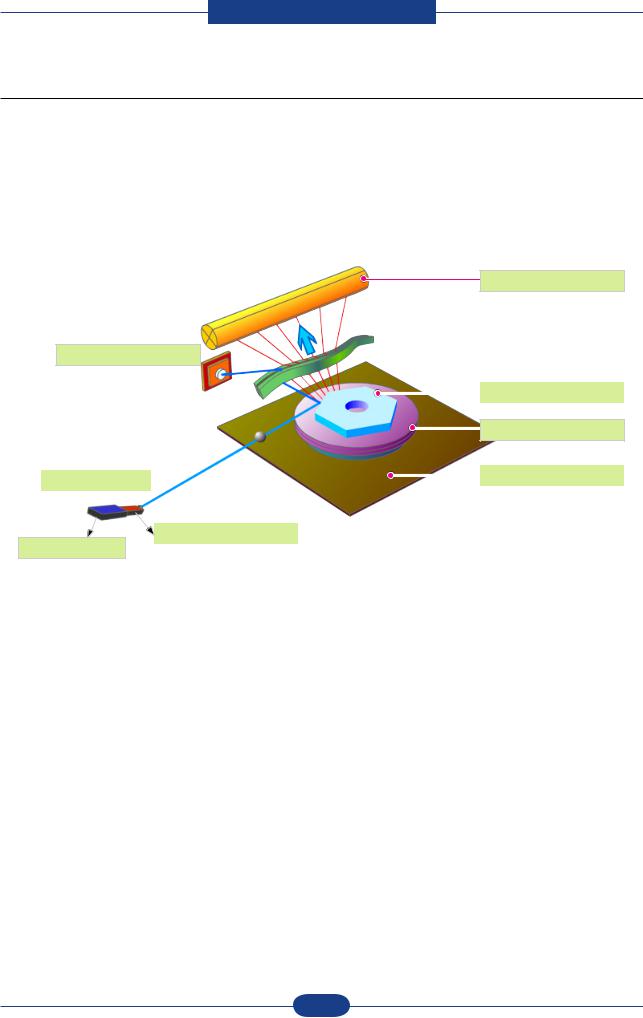
2.2.2.5 LSU (Laser Scanner Unit)
It is the core part of the LBP which switches from the video data received to the controller to the electrostatic latent image on the OPC drum by controlling laser beam, exposing OPC drum, and turning principle of polygon mirror. The OPC drum is turned with the paper feeding speed. The /HSYNC signal is created when the laser beam from LSU reaches the end of the polygon mirror, and the signal is sent to the controller. The controller detects the /HSYNC signal to adjust the vertical line of the image on paper. In other words, after the /HSYNC signal is detected, the image data is sent to the LSU to adjust the left margin on paper. The one side of the polygon mirror is one line for scanning.
OPC Drum
Photo Diode
|
|
|
|
|
|
|
|
|
|
|
Polygon Mirror |
|
|
|
|
|
|
|
|
|
|||
|
|
|
|
|
|
|
|
|
|
|
|
|
|
|
|
|
|
|
|
|
|
|
Polygon Motor |
|
|
|
|
|
|
|
|
|
|
|
|
|
|
|
|
|
|
|
|
|
|
|
|
|
LD Driver circit |
|
|
|
|
|
|
|
|
Motor Driver |
|
|
|
|
|
|
|
|
|
|
|
|
|
|
|
|
|
|
|
|
|
|
|
|
|
|
|
|
|
LD(Laser Diode) |
|
|
|
|
|
|
|
Protector panel |
|
|
|
|
|
|
|
|
|
||
|
|
|
|
|
|
|
|
|
|||
Service Manual |
2-13 |
Samsung Electronics |
|

Product spec and feature
2.2.2.6 Print Cartridge
By using the electronic photo process, it creates a visual image. In the print cartridge, the OPC unit and the toner cartridge unit are in a body. The OPC unit has OPC drum and charging roller, and the toner cartridge unit has toner, supply roller, developing roller, and blade (Doctor blade)
-Developing Method : Non-contacting method
-Toner : Non magnetic 1 component pulverized type toner
-The life span of toner : 2,000 or 5,000 pages (LSA Pattern/A4 standard)
-Toner remaining amount detecting sensor : Yes
-OPC Cleaning : Cleaning blade type
-Management of disusable toner : Collect the toner by using Cleaning Blade
-OPC Drum protecting Shutter : No
-Classifying device for toner cartridge : ID is classified by CRUM. except for initial cartridge.
2 Cleaning Roller
|
0.32mW |
|
|
|
|
4 |
|
|
|
- |
+ |
-1.25KV ~ -1.45KV |
|
-750V |
-250V |
|
|
-130V |
|
1 |
|
|
|
8 Cleaning Blade |
|
3 |
|
|
6 |
|
|
|
VD = -430V |
|
|
|
|
|
5 


VS = -680V

 +4.2kV
7 


Service Manual |
2-14 |
Samsung Electronics |
|

Product spec and feature
2.2.3 Engine H/W Specifications
2.2.3.1 Main Board
The Engine Board and the Controller Board are in one united board, and it is consisted of CPU part and print part in functional aspect. The CPU is functioned as the bus control, I/O handling, drivers, and PC interface. The main board sends the Current Image of Video data to the LSU and manages the conduct of Electrophotography for printing. It is consisted of the circuits of the motor (paper feed, pass) driving, clutch driving, pre-transfer lamp driving, current driving, and fan driving.
The signals from the paper feed jam sensor and paper empty sensor are directly inputted to the main board.
HVPS CN4
( 24V : 13 14 24VS : 9 10 )
LCD/OPE
EEPROM
U3, U4
SMPS CN10
( 24V : 4 6 8 10 5V : 12 14 16 )
DC to DC Converter (3.3V) U15
DC to DC Converter (1.3V) U5
MP Sensor /
Actuator
SDRAM
U6, U7
Option Memory Slot
ASIC
U8
Network
Interface & IC
USB
Port & IC
NOR Flash
U17, U18
Service Manual |
2-15 |
Samsung Electronics |
|

Product spec and feature
2.2.3.1(a) Asic(CHRUS3)
•CPU Core : ARM1020E
-32KB instruction cache and 32KB data cache
•Operating Frequency
-CPU Core : over 300MHz
-System Bus : 100MHz
•SDRAMC
-32Bits Only, 100MHz
-5 Banks (Up to 128MB per Bank)
•ROMC
-4 Banks (Up to 16MB per Bank)
•IOC
-6 Banks (Up to 16MB per Bank
•DMAC
-4 Channels
•HPVC
-Dual/Single Beam
-LVDS Pad(VDO, HSYNC)
•UART
-5 Channels (1 Channels Supports DMA Operation)
•PCI Controller
-32Bits, 33/66MHz
-PCI Local Bus Specification rev2.2 Complaint
-Host / Agent Mode (Support 4 Devices in Host Mode)
•NAND Flash Controller
-8/16Bits, H/W EEC Generation
-Auto Boot Mode (Using Internal SRAM, 4KB)
•MAC
-10M/100Mbps
-Full IEEE 802.3 Compatibility
•Engine Controller
-LSU Interface Unit
-Step Motor : 2 Channels
-PWM : 8 Channels
-ADC : 6 Channels
•I2C Controller
-I2C(S-BUS) Slave Device Support(I2C Version 2.1)
•RTC
-RTC Core Voltage : 3V
•PLL
-3 PLL : MAIN, PCI, PVC
Service Manual |
2-16 |
Samsung Electronics |
|

Product spec and feature
2.2.3.1(b) Memory
•Flash Memory : It stores System Program and downloads the System Program through PC Interface, and in case of model for export it compresses the PCL font, then stores it.
-Capacity : 16M Byte (NOR Flash)
-Random Access Time : 10 us (Max)
-Serial Page Access Time : 50ns (Min)
•DRAM : It is used as Swath Buffer, System Working Memory Area, etc. when printing.
It stores Font List, compressed into Flash memory, on DRAM and uses it as PCL font in case of model for export.
-Capacity : 64MB Byte(Basic), up to 192M Byte
-Type : SDRAM 100MHz/133MHz , 32bit
2.2.3.1(C) Sensor Input Circuit
■Paper Empty Sensing
The Paper empty sensor (Photo Interrupter) on the HVPS informs the state of paper to CPU whether it is empty or not with operation of the actuator.
When cassette is empty, it detects the fact by reading the E20 of CPU, and then informs the fact by displaying the RED.
■Paper Feeding/With Toner Cartridge Sensing
When paper passes the actuator (feed sensor part), it detects the signal of Photo interrupter, informs the paper feeding state to CPU, and then sprays the image data after certain time.
If it doesn t detect the feed sensor within 1sec. after paper is fed, paper Jam0 is occurred (LED will be display Orange color). The fact whether the developer is inserted or not is detected by CRUM. After the developer is mounted, the sub-CRUM can read the information of toner cartridge from contact with CRUM involved in toner cartridge. If the information of toner cartridge is invalid, it will show invalid sign on LED.
■Paper Exit Sensing
It detects paper state whether paper gets out from the set with operation of exit sensor on the HVPS and actuator on the frame. Paper detects the on/off time of exit sensor by reading D22 of CPU, and the normal operation or jam information is informed to the CPU.
The paper JAM2 is informed. (LED will be display Orange color)
■Cover Open Sensing
The Cover open sensor is located on the HVPS. After the front cover is opened, +24VS (DC fan, Solenoid, Main Motor, Polygon motor part of LSU and HVPS), which is supplied to the each unit, is cut off. The cover-open sensing is operated by the D23 of CPU.
In case, the red will be ON for informing the facts to user.
■DC FAN / SOLENOID Driving
It is driven by transistor and controlled by D14(FAN MAIN), E16(FAN DUPLEX), C23(PICK-UP CLUTCH), C18(REGI CLUTCH), D15(MPF CLUTCH) of CPU.
When it is high, the fan is driving by turning on the TR, and it is off when the sleep mode is selected. There are three solenoids, and they are driven by paper pick-up, regi and MPF signal. It is turned on or off by C23, C18, D15 of CPU.
The diode protects the driving TR from the noise pulse, which is flown when the solenoid id de-energizing. FAN Driving Circuit is driven by Transistor, and controlled by D14, E16 of CPU.
Service Manual |
2-17 |
Samsung Electronics |
|

Product spec and feature
■Motor Driving
The main motor driving circuits is on the BLDC Motor Ass y Unit. Main Controller has the interfacing circuits. There is motor driver IC on the motor control board of Motor Ass y Unit.
The exit motor driving circuits is formed when the driver IC is selected. The AN44060A Motor Driver IC is used in this case. The resistance Rs value for sensing and voltage value for the V reference can be
changed by motor driving voltage value. The motor driving voltage is calculated with the following formula.
IN 0, 2 |
IN 1, 3 |
Output Current |
|
|
|
L |
L |
Vref / (10*Rs) = Iout |
|
|
|
H |
L |
Vref / (15*Rs) = Iout * 2/3 |
|
|
|
L |
H |
Vref / (30*Rs) = Iout * 1/3 |
|
|
|
H |
H |
0 |
|
|
|
The motor driving circuit is formed when the Driver IC is selected. The A3977 Motor Driver IC is used in this case. The resistance Rs value for sensing and voltage value for the V reference can be changed by motor driving voltage value.
The motor driving voltage is calculated with the following formula. I = Vref / Rs, wherein Vref is (R1 5V) / (R1+R2).
Service Manual |
2-18 |
Samsung Electronics |
|

Product spec and feature
2.2.3.2 SMPS & HVPS board
The SMPS supplies DC Power to the System.
It takes 110V/220V and outputs the +5V, +24V to supply the power to the main board and all other boards. The HVPS board creates the high voltage of THV/MHV/Supply/Dev and supplies it to the developer part for making best condition to display the image. The HVPS part takes the 24V and outputs the high voltage for THV/MHV/BIAS, and the outputted high voltage is supplied to the toner, OPC cartridge, and transfer roller
2.2.3.2(a) HVPS (High Voltage Power Supply)
•Transfer High Voltage (THV+)
□Input Voltage: 24 V DC ± 15%
□Output Voltage: MAX +5.0KV(Duty Variable)
□Line Regulation : under±3% (fluctuation input 21.6V ~ 27.6V)
□ Output Voltage Rising Time 50ms Max
□Output Voltage Falling Time : 100 ms Max
□Fluctuating transfer voltage with environmental various : 0 V~ 5 KV
□Environment Recognition Control Method : The THV-PWM ACTIVE is transfer active signal. It detects the resistance by recognizing the voltage value, F/B, while permits the environmental recognition voltage.
□Output Voltage Control Method : Transfer Output Voltage is outputted and controlled by changing Duty of THVPWM Signal.
•Charge Voltage (MHV)
□Input Voltage : 24 V DC ± 15%
□Output Voltage : -1.2KV ~ -1.8KV DC ± 3%
□Output Voltage Rising Time : 50 ms Max
□Output Voltage Falling Time : 50 ms Max
□Output Control Signal(MHV-PWM) : CPU is HV output when PWM is Low
•Cleaning Voltage (THV-)
□-1.2KV ± 15%
□The (+) Transfer Voltage is not outputted because the THV PWM is controlled with high.
□The (-) Transfer Voltage is outputted because the THV-Enable Signal is controlled with low
□The output fluctuation range is big because there is no Feedback control & connection Resistor.
•Developing Voltage (DEV)
□Input Voltage : 24 V DC ± 15%
□Output Voltage: -200V ~ -600V DC ± 3%
□Output Voltage Fluctuation Method : PWM Control
□Line Regulation : under±3% (fluctuation input 21.6V ~ 27.6V)
□Load Regulation : Under ±3%
□Output Voltage Rising Time : 50 ms Max
□Output Voltage Falling Time : 50 ms Max
□Output Control Signal (BIAS-PWM) : the CPU output is HV output when PWM is low.
•Supply
□Output Voltage : -300V ~ -800V DC ± 5% (ZENER using, DEV )
□Line Regulation : under±3% (fluctuation input 21.6V ~ 27.6V)
□Load Regulation : Under ±3%
□Output Voltage Rising Time : 50 ms Max
□Output Voltage Falling Time : 50 ms Max
□Output Control Signal (BIAS-PWM) : the CPU is HV output when PWM is low
Service Manual |
2-19 |
Samsung Electronics |
|

Product spec and feature
CN1
SW2  (Main PBA CON.)
( Rear-Cover
Open Switch )
SW1
( Front -Cover
Open Switch )
MHV
DEV
OPC
SUPPLY
THV
VARISTOR
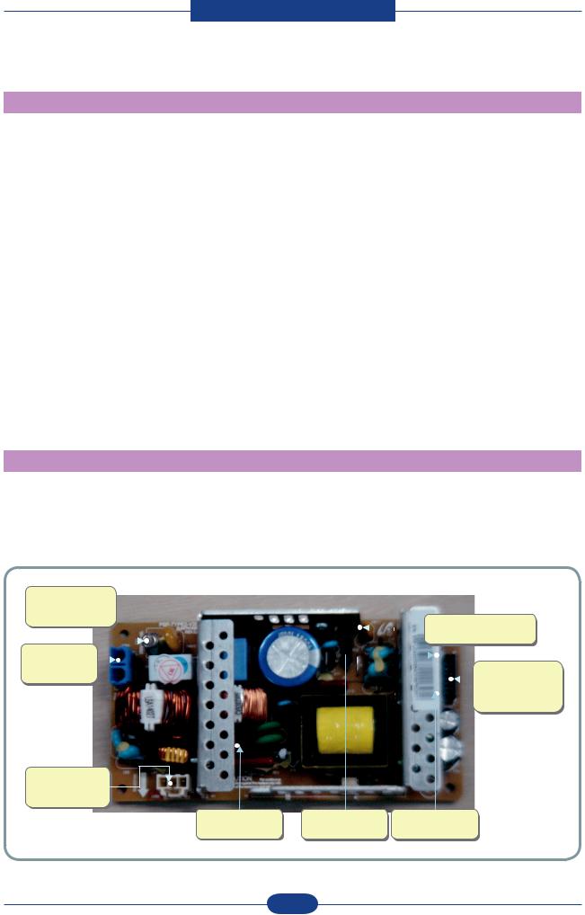
2.2.3.2(b) SMPS (Switching Mode Power Supply)
It is the power source of entire system. It is assembled by an independent module, so it is possible to use for common use. It is mounted at the side of the set. It is consisted of the SMPS part, which supplies the DC power for driving the system, and the AC heater control part, which supplies the power to fuser. SMPS has two output channels. Which are +5V and +24V.
•AC Input
□Input Rated Voltage: AC 110V ~ 127V / AC 220V ~ 240V
□Input Voltage fluctuating range : AC 90V ~ 135V / AC 180V ~ 270V
□Rated Frequency : 50/60 Hz
□Frequency Fluctuating range : 47 ~ 63 Hz
□Input Current : Under 4.0Arms / 2.0Arms (But, the status when lamp is off or rated voltage is inputted/ outputted )
Service Manual |
2-20 |
Samsung Electronics |
|
Product spec and feature
• Rated Output Power
NO |
ITEM |
CH1 |
CH2 |
Remark |
1 |
CHANNEL NAME |
+5V |
+24.0V |
|
|
|
|
|
|
2 |
CONNECTOR PIN |
CON 4 |
CON 4 |
CON 4 |
|
|
5V PIN: 11,13,15 |
24V PIN:3,5,7,9, |
24VS PIN: 2 |
|
|
GND PIN: 12,14,16 |
GND PIN:4,6,8,10 |
|
|
|
|
|
|
3 |
Rated Output |
+5.1V±2% |
+24V -10%/+10% |
|
|
|
(5.0~5.2V) |
(21.6~26.4V) |
|
|
|
|
|
|
4 |
Nor. Output Current |
1.6A |
1.8 A |
|
|
|
|
|
|
5 |
Max. Output Current |
2.0 A |
2.5 A |
|
|
|
|
|
|
6 |
RIPPLE &NOISE |
Under100mVp-p |
Under 500mVp-p |
|
|
Voltage |
|
|
|
|
|
|
|
|
7 |
Normal output |
8.16W |
43.2W |
|
|
|
|
|
|
8 |
Maximum output |
10.2W |
60.0W |
|
|
|
|
|
|
9 |
Protection for loading |
Shut down or Fuse |
Shut down(2.8A~4.5A)or |
|
|
shortage and overflowing |
Protection |
Voltage Drop(trip-10%) |
|
|
current |
(Under LPS spec) |
|
|
|
|
|
|
|
• Consumption Power |
|
|
|
|
|
|
|
||
NO |
ITEM |
System |
||
1 |
Stand-By |
|
Less than 60W |
|
|
|
|
|
|
2 |
PRINTING |
|
Less than 400W |
|
|
|
|
|
|
3 |
Sleep-Mode |
|
Less than 8W |
|
|
|
|
|
|
F01
220V |
: 250V 8A |
|
|
|
|
|
|
|
|
|
|
|
|
|||
|
|
|
|
|
|
|
|
|
|
|
|
|||||
110V |
: 250V 10A |
|
|
|
|
|
|
|
|
|
|
SW2 |
||||
CON1 |
|
|
|
|
|
|
|
|
|
|
||||||
|
|
|
|
|
|
|
|
|
|
|
|
|||||
|
|
|
|
|
|
|
|
|
|
|
|
|||||
|
|
|
|
|
|
|
|
|
|
|
|
|||||
|
|
|
|
|
|
|
|
|
|
|
|
|||||
(AC POWER |
|
|
|
|
|
|
|
|
|
|
|
|
|
|
CON2 |
|
|
|
|
|
|
|
|
|
|
|
|
|
|||||
CON.) |
|
|
|
|
|
|
|
|
|
|
|
|||||
|
|
|
|
|
|
|
|
|
|
|
|
|
|
|
|
(Main PBA CON.) |
|
|
|
|
|
|
|
|
|
|
|
|
|
|
|
|
24V : 3 5 7 9 |
|
|
|
|
|
|
|
|
|
|
|
|
|
|
|
|
5V : 11 13 15 |
CON1
(Heat Lamp CON.)
F02 |
F71 |
F72 |
250V 3.15A |
250V 4A |
250V 4A |
Service Manual |
2-21 |
Samsung Electronics |
|
 Loading...