


 Loading...
LASER PRINTER
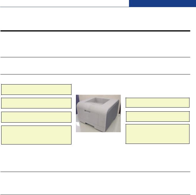
ML-347x Series
ML-3471ND/XAX
Basic Model : ML-3471ND
SERVICE Manual 
LASER PRINTER |
|
The keynote of Product |
|
|
Upgrade to Speed_up model(ML-347x) |
||
|
|||
|
of the ML-3050 serie |
||
|
1. Speed: Up to 33ppm (Ltr. 35ppm), |
||
|
|
1200x1200dpi Effective output |
|
|
2. Paper Path: MPF Type Cassette |
||
|
3. Emulation: PCL6, PS3 |
||
|
4. CPU: SPGPv3 |
||
|
5. Memory: 16~64MB Standard |
||
|
6. Cassette: 250 sheet Cassette |
||
|
7. MP: 50 sheet MP |
||
|
8. Lan: 10/100 Base TX (ML-3471ND) |
||
|
9. I/O: USB 2.0, IEEE1284 |
||
|
10. Toner: 10K Toner (4K initial) |
||
|
11. Option: 802.11b/g Wireless N/W, |
||
ML-347x Series |
|
250 sheet Opt. SCF |
|
12. Duplex: Built in Duplex |
|||
|
|||
|
|
|
|
|
|
|
|

Contents
1. Precautions
1.1 Safety Warning 


 1-1
1-1
1.2 Caution for safety |
1-2 |
1.3ESD Precautions


 1-4
1-4
2.Product spec and feature
2.1Product Specifications 


 2-1
2-1
2.1.1Product Overview 


 2-1
2-1
2.1.2Specifications 


 2-1
2-1
2.1.3Model Comparison Table 


 2-6
2-6
2.1.4Accessory List 


 2-6
2-6
2.2System Overview 


 2-7
2-7
2.2.1System Construction 


 2-7
2-7
2.2.2Mechanical Parts Specifications 


 2-12
2-12
2.2.3Engine H/W Specifications 


 2-18
2-18
2.2.4S/W Descriptions 


 2-28
2-28
3.Disassembly and Reassembly
3.1General Precautions on Disassembly 


 3-1
3-1
3.2Screws used in the Printer 


 3-2
3-2
3.3Front Cover 


 3-4
3-4
3.4MP Tray Ass'y 


 3-5
3-5
3.5Rear Cover 


 3-6
3-6
3.6Fuser Ass'y 


 3-7
3-7
3.7Top Cover 


 3-10
3-10
3.8OPE Unit


 3-11
3-11
3.9 Side Cover (Left, Right) |
3-12 |
3.10 Shield Controller Ass'y 


 3-14
3-14

Continued
3.11Drive Ass'y 


 3-15
3-15
3.12Duplex Drive Ass'y 


 3-16
3-16
3.13Shield SMPS Ass'y 


 3-17
3-17
3.14Connection PCB 


 3-18
3-18
3.15 Fuser Drive Ass'y |
3-19 |
3.16Fan 


 3-20
3-20
3.17Pick Up Roller Ass'y 


 3-21
3-21
3.18Duplex Guide Housing (With Feed Roller) 


 3-22
3-22
3.19HVPS Housing 


 3-23
3-23
3.20Cover Mid Front 


 3-24
3-24
3.21MPF Housing 


 3-24
3-24
3.22 Feed Roller Parts |
3-25 |
3.23Pick Up Gear Ass'y & Solenoids 


 3-27
3-27
3.24Exit Roller


 3-27
3-27
3.25LSU 


 3-28
3-28
3.26TERMINAL 


 3-28
3-28
3.27Transfer Roller Parts 


 3-29
3-29
4.Alignment & Troubleshooting
4.1Alignment and Adjustments


 4-1
4-1
4.1.1Sample Pattern


 4-1
4-1
4.1.2Control Panel 


 4-2
4-2
4.1.3Consumables and Replacement Parts 


 4-7
4-7
4.1.4LED Status Error Message


 4-7
4-7
4.1.5Abnormal Image Printing and Defective Roller

 4-10
4-10
4.1.6 How to use DCU |
4-11 |
4.1.7Paper Jam 


 4-16
4-16
4.1.8Download & Reset F/W


 4-22
4-22
4.2Troubleshooting 


 4-23
4-23
4.2.1Procedure of Checking the Symptoms


 4-23
4-23
4.2.2The cause and solution of Bad image 


 4-24
4-24

Continued
4.2.3The cause and solution of the bad discharge 

 4-40
4-40
4.2.4The cause and solution of the malfunction 


 4-49
4-49
4.2.5Toner Cartridge Service 


 4-59
4-59
4.2.6The cause and solutions of bad environment of the software 4-64
5.Exploded Views & Parts List
5.1Main 


 5-2
5-2
5.2Cover Ass'y 


 5-4
5-4
5.3Front Cover Ass'y 


 5-6
5-6
5.4Rear Cover Ass'y


 5-8
5-8
5.5OPE Cover Ass'y


 5-9
5-9
5.6Frame 


 5-10
5-10
5.7MP Ass'y 


 5-14
5-14
5.8Main Drive Ass'y 


 5-16
5-16
5.9Fuser Drive Ass'y 


 5-18
5-18
5.10 Duplex Unit (Optional) |
5-19 |
5.11Fuser Unit


 5-21
5-21
5.12Cassette Unit 


 5-23
5-23
6.System Diagram
6.1Block Diagram 


 6-1
6-1
6.1Connection Dia ram 


 6-2
6-2
7.Reference Information
7.1Troubleshooting Tools


 7-1
7-1
7.2Acronyms and Abbreviations 


 7-2
7-2
7.3Selecting printer locations 


 7-4
7-4

Continued
7.4LAN (Optional Function)


 7-4
7-4
7.5Sample Tests Patterns 


 7-5
7-5
7.6Series model solution(ML-3470D and ML-3471ND) 
 7-6
7-6
7.6.1Double Feed Erro 


 7-6
7-6
7.6.2Jam0


 7-7
7-7
7.6.3Jam1


 7-8
7-8
7.6.4No Paper/Add Paper" error on the printer and have been unable
to clear it, even when they have verified there is paper in the printer |
7-9 |
7.6.5Open Cover Error 


 7-10
7-10
7.6.6Low Toner 


 7-11
7-11
7.6.7Over Heat Error 


 7-12
7-12
7.6.8Low Heat Error 


 7-13
7-13
7.6.9Fuser Door Open 


 7-14
7-14
7.6.10A noise troubleshooting tree 


 7-15
7-15
7.6.11LSU Error 


 7-16
7-16
7.6.12Scan Lock Error 


 7-17
7-17
7.6.13 Nothing Displayed on LCD |
7-18 |
7.6.14All black printing 


 7-19
7-19
7.6.15Blank Copy 


 7-20
7-20
7.6.16Images at 1 Copy 


 7-21
7-21
7.6.17Glass Broken 


 7-22
7-22
7.6.18Document Jam 


 7-23
7-23
7.7 Parts Life Cycle Maintenance Table |
7-24 |
7.7.1Parts Life Cycle Maintenance Table


 7-24
7-24
7.7.2Toner Cartridge Criterion 


 7-24
7-24
7.8Model Information 


 7-25
7-25
7.8.1Model List 


 7-25
7-25
7.8.2 Understanding for Model Code |
7-25 |
7.8.3Understanding Material Code & Name 


 7-26
7-26
7.8.4F/W Upgrade Method 


 7-26
7-26

1 Precautions
1. Precautions
The cautions below are items needed to keep in mind when maintaining and servicing.
Please read carefully and keep the contents in mind to prevent accidents while servicing and to prevent the machine from getting damaged.
1.1 Safety Warning
(1) Request service by qualified service person.
Service for this machine must be performed by a Qualified service person. It is dangerous if unqualified service personnel or users try to fix the machine.
(2) Do not rebuild.
Do not attach or change parts discretionary. Do not dissemble, fix of rebuilt it. If so, printer will abnormally work and electric shock or fire may occur.
(3) Laser Safety Statement
The Printer is certified in the U.S. to conform to the requirements of DHHS 21 CFR, chapter 1 Subchapter J for Class 1(1) laser products, and elsewhere, is certified as a Class I laser product conforming to the requirements of IEC 825.
Class I laser products are not considered to be hazardous. The laser system and printer are designed so there is never any human access to laser radiation above a Class I level during normal operation, user maintenance, or prescribed service condition.
Warning >> Never operate or service the printer with the protective cover removed from Laser/Scanner assembly. The reflected beam, although invisible, can damage your eyes. When using this product, these basic safety precautions should always be followed to reduce risk of fire, electric shock, and injury to persons.
|
Service Manual |
1-1 |
Samsung Electronics |
|
|
|
|

Precautions
1.2 Caution for safety
1.2.1 Noxious Material Precaution
The toner in a printer cartridge contains a chemical material, which may harm human body if it is swallowed. Please keep children out of reach of the toner cartridge.
1.2.2 Electric Shock or fire Precaution
It is possible to get electric shock or burn by fire if you don't fallow the instructions of the manual.
(1)Use exact voltage. Please use an exact voltage and wall socket. If not, a fire or an electric leakage can be caused.
(2)Use authorized power cord. Do use the power cord supplied with PRINTER. A fire can happen when over current flows in the power cord.
(3)Do not insert many cords in an outlet. A fire can be occurred due to flow over current in an outlet.
(4)Do not put water or extraneous matter in the PRINTER. Please do not put water, other liquid, pin, clip, etc. It can cause a fire, electric shock, or malfunction. If this occurs, turn off the power and remove the power plug from outlet immediately.
(5)Do not touch the power plug with wet hand. When servicing, remove the power plug from outlet. Do not insert or take off it with wet hand. Electric shock can be occurr.
(6)Caution when inserting or taking off the power plug. The power plug has to be inserted completely. If not, a fire can be caused due to poor contact. When taking off the power plug, grip the plug and take it off. If grip the line and pull over, it could be damaged. A fire or electric shock could happen.
(7)Management of power cord. Do not bend, twist, or bind it and place other materials on it. Do not fix with staples. If the power cord gets damaged, a fire or electric shock can happen. A damaged power cord must be replaced immediately. Do not repair the damaged part and reuse it. A repaired part with plastic tape can be cause a fire or electric shock. Do not spread chemicals on the power cord. Do not spread insecticide on the power cord. A fire or electric shock can be happen due to thinner(weak) cover of the power cord.
(8)Check whether the power outlet and the power plug are damaged, pressed, chopped, or blazing fire or not. When such inferiorities are found, repair it immediately. Do not make it pressed or chopped when moving the machine.
(9)Caution when there is thundering or lightning, and being flash of lightening. It causes a fire or electric shock. Take the power plug off there is thunder. Do not touch cable and device when thundering and flash of lightening.
(10)Avoid the place where is moisture or has dust. Do not install the printer where lots of dust or around humidifier. A fire can occurred. A plug part need to clean well with dried fabric to remove dust. If water drops are dripped on the place covered with dust, a fire can occurred.
(11)Avoid direct sunlight. Do not install the printer near window where direct contacts to the sunlight. If the machine contacts sunlight long time, the machine cannot work properly because inner temperature of the machine is getting hotter. A fire can occur.
(12)Turn off the power and take off the plug when smoke, strange smell, or sound from the machine. If you keep using it, a fire can be occurred.
(13)Do not insert steel or metal piece inside/outside of the machine. Do not put steel or metal piece into a ventilator. An electric shock could happened.
1-2 Service Manual
Samsung Electronics

Precautions
1.2.3 Handling Precautions
If you ignore this information, you could harm machine and could be damaged.
(1)Do not install it on different levels, or slanted floor.
Please confirm whether it is balanced or not after installation. If it is unbalanced, an accident can be happened due to the machine falling over.
(2)Be careful not to insert a finger or hair in the rotating unit.
Be careful not to insert a finger of hair in the rotating unit (motor, fan, paper feeding part, etc) while the machine is operating. Once it happens, you could be harmed.
(3)Do not place a pot containing water/chemical or small metals. If they got caught into the inner side of machine, a fire or electric shock can be occurred.
(4)Do not install it where lots of moisture or dust exists or where raindrop reaches. A fire or electric shock can be caused.
(5)Do not place a candlelight, burning cigarette, and etc. on the machine. Do not install it near to heater. A fire can be occurred.
1.2.4 Assembly/Disassembly precaution
When replacing parts, do it very carefully. Memorize the location of each cable before replace parts for reconnecting it afterwards. Do memorize. Please perform the steps below before replace or disassembly the parts.
(1)Check the contents stored in the memory. All the information will be erased after replacing main board. The information needed to keep has to be written down.
(2)Before servicing or replacing electric parts, take off a plug.
(3)Take off printer cables and power cord connected to printer.
(4)Do use formal parts and same standardized goods when replacing parts.Must check the product name, part cord, rated voltage, rated current, operating temperature, etc.
(5)Do not give an over-force when release or tighten up the plastic parts.
(6)Be careful not to drop the small parts such as screws in the printer.
(7)Be careful not to change the location of small parts such as screws when assembling and disassembling.
(8)Do remove dust or foreign matters completely to prevent fire of tracking, short, or etc.
(9)After finished repair, check the assembling state whether it is same as before the repair or not.
|
Service Manual |
1-3 |
Samsung Electronics |
|
|
|
|

Precautions
1.3 ESD Precautions
Certain semiconductor devices can be easily damaged by static electricity. Such components are commonly called “Electrostatically Sensitive (ES) Devices”, or ESDs. Examples of typical ESDs are: integrated circuits, some field effect transistors, and semiconductor “chip” components.
The techniques outlined below should be followed to help reduce the incidence of component damage caused by static electricity.
Caution >>Be sure no power is applied to the chassis or circuit, and observe all other safety precautions.
1.Immediately before handling a semiconductor component or semiconductor-equipped assembly, drain off any electrostatic charge on your body by touching a known earth ground. Alternatively, employ a commercially available wrist strap device, which should be removed for your personal safety reasons prior to applying power to the unit under test.
2.After removing an electrical assembly equipped with ESDs, place the assembly on a conductive surface, such as aluminum or copper foil, or conductive foam, to prevent electrostatic charge buildup in the vicinity of the assembly.
3.Use only a grounded tip soldering iron to solder or desolder ESDs.
4.Use only an “anti-static” solder removal device. Some solder removal devices not classified as “anti-static” can generate electrical charges sufficient to damage ESDs.
5.Do not use Freon-propelled chemicals. When sprayed, these can generate electrical charges sufficient to damage ESDs.
6.Do not remove a replacement ESD from its protective packaging until immediately before installing it. Most replacement ESDs are packaged with all leads shorted together by conductive foam, aluminum foil, or a comparable conductive material.
7.Immediately before removing the protective shorting material from the leads of a replacement ESD, touch the protective material to the chassis or circuit assembly into which the device will be installed.
8.Maintain continuous electrical contact between the ESD and the assembly into which it will be installed, until completely plugged or soldered into the circuit.
9.Minimize bodily motions when handling unpackaged replacement ESDs. Normal motions, such as the brushing together of clothing fabric and lifting one’s foot from a carpeted floor, can generate static electricity sufficient to damage an ESD.
1-4 Service Manual
Samsung Electronics
Product specification and feature
22. Product specification and feature
2.1 Product Specifications
2.1.1 Product Overview
Up to 33ppm (Ltr. 35ppm)
PCL6, PS3, 1200x1200dpi
400 MHz, 64MB Standard
-10/100 Base TX
-Opt. 802.11b/g Wireless N/W
ML-3471ND |
USB 2.0, IEEE1284 |
|
|
10K Toner (4K Standard)
Built in Duplex
-250 sheet Cassette
-50 sheet MP
-250 sheet Opt. SCF
2.1.2Specifications
 Product Specifications are subject to change without notice. See below for product specifications.
2.1.2.1 General Print Engine
ML-347x Series |
|
ML-3470D |
|
ML-3471ND |
Engine Speed |
Simplex |
Up to 33 ppm in A4 (35 ppm in Letter) |
|
|
|
Duplex |
Up to 17 ipm in A4 (17.5 ipm in Letter) |
|
|
|
|
|
|
|
Warmup time |
From Sleep |
Less than 15 sec, Cold warm-Up time : 15sec |
||
|
|
|
|
|
FPOT |
From Ready |
Less than 8.5 sec |
|
|
|
|
|
|
|
|
From Idle |
Less than 23.5 sec |
|
|
|
|
|
|
|
|
From Coldboot |
Less than 30 sec |
|
|
|
|
|
|
|
Resolution |
- |
Up to 1,200 x 1,200 dpi effective output |
|
|
|
Service Manual |
2-1 |
Samsung Electronics |
|
|
|
|
Product specification and feature
2.1.2.2 Controller & S/W
ML-347x Series |
|
ML-3470D |
ML-3471ND |
Processor |
|
Samsung 400 MHz |
|
Memory |
Std. |
32 MB |
64 MB |
|
Max. |
288 MB |
320 MB |
Printer Languages |
- |
PostScript3, PCL6, SPL, IBM ProPrinter, EPSON |
|
Fonts |
- |
45 scalable, 1 bitmap, 136 PostScript3 fonts |
|
Driver |
Default Driver |
SPL |
|
|
|
|
|
|
Supporting OS |
Windows 2000/XP/2003/Vista |
|
|
|
Various Linux OS including Red Hat, Caldera, Debian, Mandrake, Slackware, |
|
|
|
SuSE and Turbo Linux |
|
|
|
Mac OS 8.6~9.2/10.1~10.4 |
|
|
WHQL |
Windows XP/2000/2003 |
|
|
Compatibility |
PCL6: Win95/98/NT4.0/2000/Me/XP/2003 |
|
|
|
PS3: Win9x/NT4.0/2000/Me/XP/2003 PPD, Mac PPD, Linux PPD |
|
|
|
KS/KSSM: DOS |
|
Wired Network |
Protocol |
External : SPX/IPX, TCP/IP, SNMP, HTTP 1.1 |
|
|
Supporting OS |
Microsoft Windows 98/ME/2000/XP/2003 Microsoft Windows NT 4.xMac OS |
|
|
|
8.6 and aboverVarious Linux OS including Red Hat, Caldera, Debian, |
|
|
|
Mandrake, Slackware, SuSE and Turbo LinuxNovell 4.x,5.x,6.x |
|
Wireless Network |
Protocol |
External : SPX/IPX, TCP/IP, SNMP, HTTP 1.1 |
|
|
|
|
|
|
Supporting OS |
Microsoft Windows 98/ME/2000/XP/2003 Microsoft Windows NT 4.xMac OS |
|
|
|
8.6 and aboverVarious Linux OS including Red Hat, Caldera, Debian, |
|
|
|
Mandrake, Slackware, SuSE and Turbo LinuxNovell 4.x,5.x,6.x |
|
Application |
RCP |
N/A |
|
|
|
|
|
|
Status Monitor |
N/A |
|
|
Smart Panel |
YES (RCP,SM) |
|
|
Network Management |
SAS (Samsung Admin Service), SetIP |
|
Interface |
|
|
|
Parallel |
- |
IEEE 1284 |
|
USB |
- |
USB 2.0 |
|
Wired Network |
- |
N/A |
Ethernet 10/100 Base TX (Internal) |
|
|
|
|
Wireless Network |
- |
N/A |
Optional (Internal) 802.11b/g |
|
|
|
Wireless LAN (Internal) |
User Interface |
|
|
|
|
|
|
|
LCD |
- |
2 x 16 Character without backlit |
|
Key |
- |
8 Key: Stop, Toner Save, Duplex |
|
|
|
< , OK, >, Menu, Back |
|
2-2 Service Manual
Samsung Electronics

Product specification and feature
2.1.2.3 Paper Handling
ML-347x Series |
|
ML-3470D |
|
ML-3471ND |
Standard Capacity |
- |
250-sheet Cassette Tray, 50-sheet Multi Purpose Tray @ 75g/ |
||
Max. Capacity |
- |
550 sheets @ 75g/ |
|
|
Printing |
Max. Size |
216 x 356 mm (8.5" x 14") |
||
|
Min. Size |
76 x 127 mm (3.0" x 5.0") |
||
|
|
|
|
|
Multi-purpose tray |
|
|
|
|
Capacity |
- |
50 sheets @ 75g/ (20lb bond) |
||
Media sizes |
- |
A4, A5, A6, Letter, Legal, Folio, Oficio, Executive,ISO B5, JIS B5, |
||
|
|
3"x5",Monarch, No.10, DL, C5, C6 |
||
Media type |
- |
Plain Paper, Transparency, Envelope, Labels, Post Card, Card stock |
||
Media weight |
- |
16~43lb (60 to 163g/ |
) |
|
Sensing |
- |
Paper empty sensor |
|
|
Standard Cassette Tray |
|
|
|
|
Capacity |
- |
250 sheets @ 75g/ |
|
|
|
|
|
|
|
Media sizes |
- |
A4, A5, Letter, Legal, Executive, Folio, Oficio, ISO B5, JIS B5 |
||
|
|
|
|
|
Media types |
- |
Plain paper, Thick, Thin, Recycled, Archive |
||
Media weight |
- |
16~28lb (60 to 105g/ |
) |
|
Sensing |
- |
Paper empty sensor |
|
|
Optional Cassette Tray |
|
|
|
|
Capacity |
- |
250 sheets @ 75g/ |
|
|
Media sizes |
- |
A4, A5, Letter, Legal, Executive, Folio, Oficio, ISO B5, JIS B5 |
||
Media types |
- |
Plain paper, Thick, Thin, Recycled, Archive |
||
|
|
|
|
|
Media weight |
- |
16~28lb (60 to 105g/ |
) |
|
Sensing |
- |
Paper empty sensor |
|
|
Output Stacking |
|
|
|
|
Capacity |
Face-Down |
150 sheets @ 75g/ |
|
|
|
|
|
|
|
|
Face-Up |
1 sheet @ 75g/ |
|
|
Output Full sensing |
- |
N/A |
|
|
|
|
|
|
|
Duplex |
|
|
|
|
|
|
|
|
|
Supporting |
- |
Built-in |
|
|
Media sizes |
- |
A4, Letter, Legal, Folio, Oficio |
||
Media types |
- |
Plain Paper |
|
|
Media weight |
- |
20~24lb (75 to 90g/ |
) |
|
|
Service Manual |
2-3 |
Samsung Electronics |
|
|
|
|

Product specification and feature
2.1.2.4 Consumables
ML-347x Series |
|
ML-3470D |
ML-3471ND |
Toner |
Black |
4,000 pages @ ISO 19752 Coverage(Standard 4,000 pages, High Yield |
|
|
|
10,000 pages) |
|
|
Key |
Electronic key(CRUM) Only |
|
|
|
|
|
|
Life detect |
Toner gauge sensor by dot count |
|
|
|
|
|
Drum |
Yield |
12,000 Images |
|
2.1.2.5 Reliability & Service
ML-347x Series |
|
ML-3470D |
ML-3471ND |
Printing Volume |
- |
9,200 sheets-per year / 767 sheets-per month / 38 sheets-per day |
|
(SET AMPV) |
|
|
|
5.2 Max. Monthly Duty |
- |
35,000 sheets |
|
5.3 MPBF |
- |
100,000 sheets |
|
|
|
|
|
5.4 MTTR |
- |
30 min. |
|
5.5 SET Life Cycle |
- |
250,000 sheets or 5 years (whichever comes first) |
|
5.6 RDS |
Comm. Mode |
Yes |
|
|
Operation |
Yes |
|
|
|
|
|
2.1.2.6 Environment
ML-347x Series |
|
ML-3470D |
ML-3471ND |
Acoustic Noise Level |
Printing |
Less than 52.0 dBA |
|
(Sound Power/Pressure) |
|
|
|
|
Standby |
Less than 26.0 dBA |
|
|
|
|
|
|
Sleep |
Back Ground Level |
|
|
|
|
|
Power Consumption |
Ready |
Less than 130W |
|
|
AVG. |
Less than 400W |
|
|
Max/Peak |
Less than 700W |
|
|
Sleep/Power Off |
Less than 11W / Less than 0.4W |
|
Dimension(W x D x H) |
SET |
400 x 433.4 x 285 mm |
|
|
|
|
|
Weight |
SET |
10.5 kg (23.15 Pounds) |
|
|
|
|
|
|
Gross |
14.5kg (31.9 Pounds) |
|
2-4 Service Manual
Samsung Electronics

Product specification and feature
2.1.2.7 Options
ML-347x Series |
|
ML-3470D |
|
ML-3471ND |
*Memory |
- |
16 MB, 32 MB, 64 MB, 128 MB, 256MB |
|
|
|
|
|
|
|
Second Cassette |
- |
250-sheet Cassette Tray |
|
|
|
|
|
|
|
Wired Network |
- |
N/A |
|
Ethernet 10/100 Base TX |
|
|
|
|
(External) - ML-00ND |
Wireless Network |
- |
N/A |
|
802.11b/g Wireless LAN (Internal) |
Hard Disk |
- |
N/A |
|
|
Duplex Unit |
- |
Default |
|
|
* Memory : The ML-3470D or ML-3471ND has 64MB of memory which can be expanded to 320MB.
Item |
Description |
Model Code |
Size |
|
|
(order) |
|
Memory DIMM |
Exlends your Printers |
ML-00MA |
16MB |
|
memory capacity. |
ML-00MB |
32MB |
|
|
ML-00MC |
64MB |
|
|
ML-00MD |
128MB |
|
|
ML-MEM140 |
256MB |
|
|
|
|
* Use only the samsung-approved DIMM.
2.1.2.8 Others
ML-347x Series |
|
ML-3470D |
ML-3471ND |
Memory |
Upgradable Mem. Slot |
1 EA |
|
|
|
|
|
|
Upgradable Mem. Type |
100 Pin SDRAM DIMM |
|
|
|
|
|
|
Upgradable Mem. Unit |
16MB, 32MB, 64MB, 128MB, 256MB |
|
|
|
|
|
Sensor |
Paper Empty |
YES |
|
|
Paper Size |
NO |
|
|
Media Type |
NO |
|
|
Paper Full |
NO |
|
|
|
|
|
Service |
Service Item & Period |
1. Transfer Roller : 70K pages |
|
|
|
2. Fuser Unit : 80K pages |
|
|
|
3. Pick-up Roller : 150K pages |
|
|
Service Manual |
2-5 |
Samsung Electronics |
|
|
|
|

Product specification and feature
2.1.3 Model Comparison Table
|
SEC |
SEC |
SEC |
SAMSUNG |
|
ML-2550 |
ML-3050 |
ML-3471ND |
ML-3560 |
Image |
|
|
|
|
|
|
|
|
|
Engine |
SEC |
SEC |
SEC |
SEC |
Speed(ppm) |
24ppm |
28ppm |
33ppm |
33ppm |
Processor |
266MHz |
400MHz |
400MHz |
400MHz |
Resolution |
1,200X1,200 dpi |
1,200X1,200 dpi |
1,200X1,200 dpi |
1,200X1,200 dpi |
FPOT |
12 sec |
8.5 sec |
8.5 sec |
10 sec |
Emulation |
PS3, PCL6 |
PCL6 |
PS3, PCL6 |
PS3, PCL6 |
Ram(Std.) |
32MB(Max. 160MB) |
16MB(Max. 272MB) |
64MB(Max. 320MB) |
32MB(Max. 288MB) |
Interface |
IEEE1284, USB 2.0 |
IEEE1284, USB 2.0 |
IEEE1284, USB 2.0 |
IEEE1284, USB 2.0 |
Duplex |
Yes |
Factory Option |
Yes |
Option |
Paper Input |
550 Cassette, 100 MP |
250 Cassette, 50 MP |
250 Cassette, 50 MP |
500 Cassette, 100 MP |
(Capa./Type) |
|
250 SCF Opt. |
250 SCF Opt. |
500 SCF Option |
Os Compatibility |
Win 95/98/NT/2000/ |
Win 95/98/NT/2000/ |
Win 2000/ |
Win 95/98/NT/2000/ |
|
Me/XP, Mac |
Me/XP, Linux |
Me/XP, Linux |
Me/XP, Linux |
Toner |
10K |
4K/8K |
4K/10K |
6K/12 K |
|
|
|
|
|
2.1.4 Accessory List
 JC99-02059A [INA-ACCESSORY] 3903-000085 [CBF-POWER CORD] 6801-00761C [CARD-WARRANTY] 6902-000809 [BAG PE]
JC46-00293A [S/W APPLICATION-CD]
JC46-00354A [S/W APPLICATION-CD] JC68-00761B [MANUAL-REGISTRATION_FROM] JC68-01579A [MANUAL-NETWORK GUIDE] JC68-01584A [LABEL(P)-BLANK 90*25] JC68-00690A [MANUAL-(CARD)WARRANTY CARD] JC68-00761D [MANUAL-REGISTRATION] JC68-01344A [MANUAL-WARRANTY CARD] JC68-01563A [MANUAL-800 SEC CARD]
2-6 Service Manual
Samsung Electronics
Product specification and feature
2.2 System Overview
2.2.1 System Construction
2.2.1.1 SUMMARY
ML-347x Series is consisted of the Engine parts and F/W, and said engine parts is consisted of the mechanical parts comprising Frame, Feeding, Developing, Driving, Transferring, Fusing, Cabinet and H/W comprising the main control board, power board, operation panel, PC Interface.
 In ML-347x Series, the main controller is consisted of Asic(SPGPv3) parts, Memory parts, Engine Interface parts and it functions as Bus Control, I/O Handling, drivers & PC Interface by CPU.
Memory Access supports 16bit Operation, and Program Memory 32MB and Working Memory as well.
 In ML-347x Series, the paper path is consisted of 250 sheets Cassette containing friction Pad, pickup-roller, feed-roller for functioning as registration, Earth-transfer for guiding the transfer inlet, Guide-Tr for guiding sheets between transferring and fixing, Fuser, Exit Assy.
 In ML-347x Series, the driving device is consisted of f55 BLDC motor, OPC, Pick-up, Feed, Gear-Train connected with Mounting member. - to be changed
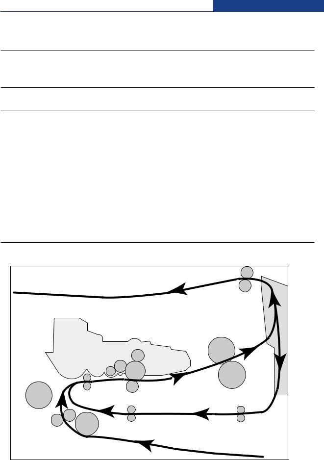
2.2.1.2 System Layout
|
Roller-Exit |
|
|
Roller-Heat |
Duplex |
|
|
|
Roller-REGI |
|
|
OPC |
|
|
Roller-MP |
|
|
Roller-Transfer |
Roller-Pressure |
|
|
|
|
Roller-Feed |
|
|
Roller-Pickup |
|
|
|
Service Manual |
2-7 |
Samsung Electronics |
|
|
|
|

Product specification and feature
2.2.1.2(a) Feeding Section
 Feeding Method : Universal Cassette Type
 Feeding Standard : Center Loading
 Feeding Capacity : Cassette 250 Sheets (75g/
 , 20lb StandardPaper)
2.2.1.2(b) Transfer Ass’y
 In Warranty( Life time) : Within 70,000 sheets printing
2-8 Service Manual
Samsung Electronics

Product specification and feature
2.2.1.2(c) Driver Ass’y
 MAIN Motor ass’y is for Cassette,MPF and Toner Cartridge
 EXIT Motor ass’y is for fuser,exit roller and the initial duplexing feeding
Drive Ass'y

 Connection


PCB
Duplex Motor
Duplex Drive Ass'y
2.2.1.2(d) Fuser Ass’y
 Fusing Type : Lamp Type
 Heat Roller : [
 28.3 with 0.1 Crown ]
 Pressure Roller Pressure Roller 2 : [electrically conductive]
 Thermistor - Temperature Detecting Sensor
 Thermostat - Overheat Protection Device
|
|
Service Manual |
|
|
|
|
|
|
|
|
|
|
|
|
|
|
|
|
|
|
|
2-9 |
|
Samsung Electronics |
|
||
|
|
||
Product specification and feature
2.2.1.2(e) LSU
 LSU is consist of LD(Laser Diode) and polygon motor control. When the controller generate the printing signal LD will turn on and Polygon motor starts.If the receiving part in LSU detect the beam and then Hsync is generated. When the rotation of poygon motor is steady, it is time of LSU ready status for printing. If either of two condition is not satisfied, LSU error is expected.
Trouble |
Failure Analysis |
Polygon Motor Error |
No steady rotation of Polygon Motor |
Hsync Error |
In spite of steady rotation of Polygon Motor, |
|
There is no generation of the Hsync signal |
|
|
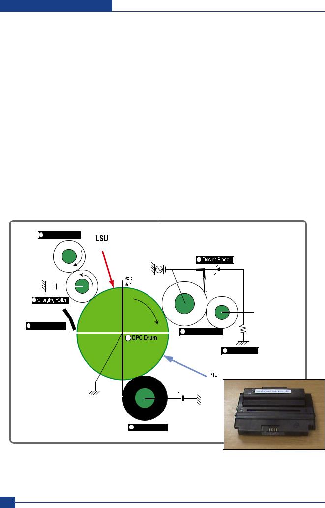
2.2.1.2(f) Toner Cartridge
 OPC Cleaning :Mechanical Cleaning by the cleaning blade.
 The recycled toner : Trash room for the recycled toner
 No shutter for protecting the OPC Drum
2 Cleaning Roller |
|
|
0.16mW |
VDC = -460V |
|
|
VPP = 1520V, f = 2.5KHz, Duty(-) = 32% |
|
|
|
4 |
-1.25KV |
|
- + |
-650V |
200V |
|
|
|
|
|
-50V |
|
1 |
|
|
8 Cleaning Blade
3


6
5 


 +4.2kV
7 


2-10 Service Manual
Samsung Electronics

Product specification and feature
2.2.1.2(g) Duplex Unit
 Duplex printing function as factory option
 Available Paper : Letter, Legal, Folio, Oficio and A4
2.21.2(h) Optional Tray (SCF)
 For customer covenience in managing paper
 Capacity : 250 sheets
|
Service Manual |
2-11 |
Samsung Electronics |
|
|
|
|
Product specification and feature
2.2.2 Mechanical Parts Specifications
2.2.2.1 Frame
 Material : PC + ABS V0 NH-1000T(Cheil Industries)
 Weight : 1.0kg
2.2.2.2 Feeding Part
 Feeding Type : Universal Cassette Type
 Feeding Standard : Center Loading
 Feeding Qty : Cassette 250 sheets (75g/
 , 20Ib paper standard) MPF 50 sheets (75g/
 , 20Ib paper standard)
Special Media 5 sheets in MPF (OHP, Envelope, Label, Post Card, Index Paper etc.)  Separating Type : Cassette-Friction Pad Type
MPF-Friction Pad Type
 Driver Type : Driving by Gearing from Main Motor
 Pick Up Roller Driver : Solenoid
 Pick Up Roller Rubber Material : EPDM + IR
  = 1.6 or more
 Paper detecting Sensor : Photo Sensor Paper Size Sensor : None
 Paper Separating Pad Material : NBB 52
 = 0.8~1.2
 Separating Pad Pressure : 190gf
 Feeding Pressure (Cassette) : 250 gf
  10% (SPRING H mm, based on 1 sheet) 320 gf
  10% (SPRING H mm, based on 250 sheet)
 Paper Exit Type : Face Down
 Feed Roller Driver : Solenoid
2.2.2.3 Transfer Ass’y
It is consisted of PTL(pre-transfer lamp) and Transfer Roller. The PTL sends a light to the OPC drum, makes the current on the drum surface to low, and improve the transfer efficiency.
The transfer roller delivers the toner of the OPC drum to the paper.
 TR Voltage : +1.3KV
  5% (based on 200
 , in accordance with media area, Transfer table) -1.20KV
  10% (In cleaning)
 Transfer Trigger Current : 6.5
 5%
5%
 Transfer Efficiency : 85% or more (All envirmnment : preferable media)
 Voltage System : Voltage PWM Control System
  Transfer Roller
-Material : NBR FOAM ROLL
-Structure : Mono layer
-Resistance : 3E +07 ~ 8E +07 (N/N)
(N/N)
-Hardness : 40 3% (ASKER-C)
-Validlength : 224.2 +0.5/-0mm
-OD : 15.0  0.5mm
0.5mm
-SHAFT Material : SUM -24L + Non-electrolysis Ni. Coating
 Life Span : Print over 70,000 sheets (in 15~30
 )
)
2-12 Service Manual
Samsung Electronics

Product specification and feature
2.2.2.4 Driver Ass’y
2.2.2.4(a) Motor
 Spec : BLDC
  62 + PM
  55 Motor (2-2 Bipolar) + PM
  42 Motor (2-2 Bipolar)
 Pull-Out Torque:
BLDC 62 : 1500 gf.cm(based on actual value) or more (1342.4rpm, 1.8A)
PM  55 : 1490gf.cm(based on actual value) or more (711pps, 0.9A)
PM  42 : 240gf.cm(based on actual value) or more (1850pps, 0.6A)
 TORQUE MARGIN (Tp/o
 Tsys) : BLDC
 62 Motor : 1500/1100 gf.cm=1.36
PM  55 Motor : 1490/1053 gf.cm = 1.41
PM  42 Motor: 240/165 gf.cm = 1.45
 Driving Frequency: BLDC
 62 Motor : 1342.4 rpm(1006.8 Clock)
PM  55 Motor : 888.75 rpm(711 pps)
PM  42 Motor : 1156 .25rpm(1850 pps)
 It is a power delivery unit by gearing: BLDC
 62 Motor -> Pickup/Feeder/Developer
PM  55 Motor -> Fuser/Exit
PM  42 Motor -> Duplex
2.2.2.4(b) Process Speed
 Print Speed : 33/35 PPM (based on A4/LTR )
 Process Speed : 211.78 mm/sec
 Jitter
 Vertical : 3
 0.018 or less in Vision System
 Horizontal : within 2% of partial magnificence error
 Orthogonality : SPEC :
  1.0 mm or less
2.2.2.4(c) Acoustic Noise
 Warming Up : 43dB or less
 Printing : 52dB or less
 Stand-by : 26dB or less
|
Service Manual |
2-13 |
Samsung Electronics |
|
|
|
|

Product specification and feature
2.2.2.5 Fixing Part (Fuser)
The fuser is consisted of the E-Coil, Heat Roller, Pressure Roller, Thermistor and Themostat. It adheres the toner to the paper with pressure and a heat to complete the printing job.
2.2.2.5(a) Halogen Lamp
 Voltage 120V : 115
  5%
5%
220V : 230  5%
5%
 Capacity : 800 Watt
  25W
25W
 Temp. Distribution : 120%
2.2.2.5(b) Temperature-Interception Device (Thermostat)
 Thermostat Type : Non-Contact type THERMOSTAT
 Control Temperature : 170
 5
5
 THERMOSTAT-ROLLER Gap : 1.6
  0.2mm
0.2mm
2.2.2.5(c) Temperature Detecting Sensor(Thermistor)
 Thermistor Type : HF-R0060 (SEMITEC 364FL Type)
 Temperature Resistance : 7
 (180
(180 )
)
 SYSTEM Temperature SETTING
-Stand by : 165  5
5
-Printing : 189  5
5 (5 minutes before) 184
  5
5 (5 minutes after)
-Overshoot : 200 less
less
-Overheat : 210 less
less
2.2.2.5(d) Heat Roller
 Length : 247.5mm
 Valid length : 224mm
 OD :
OD :  28.3 + 0.05, -0.03 (Tubing incl., Crown 0.09~-0.15)
 Material : AL(AL5052) + PFA Tubing
 Thickness : 0.9mm
 Coating Material : PFA 100%
 Coating Thickness : 20um (Thickness after abrasion)
 GND Type : H/R Bearing Grounding type By SECC Fuser lower frame
2-14 Service Manual
Samsung Electronics

Product specification and feature
2.2.2.5(e) Pressure Roller
 Shaft
Shaft
-Length : 251.3mm
-Material : SUM
-Thickness :  6(
6(  14 - RUBBER portion)
 Rubber 1
-Material : Silicon Rubber (Tubing Type :  20)
20)
-Length : 226.4mm
-Thickness : 5mm(one-side)
 Rubber 2
-Material : Silicon Rubber (Tubing Type :  16)
16)
-Length : 226.4mm
-Thickness : 5mm(one-side)
 OD : 1) 20
  0.2(Center part Crown -0.2) 2) 16
  0.2(Center part Crown -0.15)
2.2.2.5(f) Media Separating System
PI Coating with PPS Claw System
2.2.2.5(g) Safety Relevant Facts
 Proteciong device when overheating
-1st protecting device : H/W cuts off when detecting an overheating
-2st protecting device : S/W cuts off when detecting overheating
-3st protecting device : Thermostat cuts off the power
 Safety device
-The power of Fuser is cut-off after front cover is open
-The overheating safety device for customer
-The surface temperature of the Fuser Cover is under 80
|
Service Manual |
2-15 |
Samsung Electronics |
|
|
|
|

Product specification and feature
2.2.2.6 LSU (Laser Scanner Unit)
The LSU unit is controlled by video controller. It scans the video data received from video controller with laser beam by using the rotation principle of the polygon mirror to create the latent image on the OPC drum. It is the core part of LBP.
The OPC drum rotates as the same speed as the paper feeding speed. It creates the /HSYNC signal and sends it to the engine when the laser beam of the LSU reaches the end of the polygon mirror, and the engine detects the /HSYNC signal to arrange the vertical line of the image on the paper. After detecting the /HSYNC signal, the image data is sent to the LSU to arrange the its margin on the paper.
The one side of the polygon mirror is one line for scanning.
2.2.2.7 Toner Cartridge
In the toner cartridge, the OPC unit and the developer unit are in a body.
The OPC unit has OPC drum and charging roller, and the developer unit has toner, toner cartridge, supply roller, developing roller, and the blade.
2.2.2.7(a) Summary
 Developing Method : Non magnetic 1 element contacting method
 Toner : Non magnetic 1 element shatter type toner
 Charging capacity : -39.1
  3
3  C/g (KAO meas. method)
 Average OD : 8.5
  0.5
0.5  (Toner)
 Toner Qty : 125 gf/250gf (4k / 10k)
 The life span of toner: 4k/10k sheets (ISO 19752 Pattern / A4 standard )
 Toner Residual Sensor : Dot count with CRUM(CRU Monitor)
 OPC Cleaning : Collect the toner by using cleaning blade+ FILM OPC
 Handling of wasted toner : Collect the wasted toner in the cleaning frame by using cleaning blade
 OPC Drum Protecting Shutter : None
 Classifying device for toner cartridge: ID is classified by interruption of the frame channel.
2.2.2.7(b) Developing Roller
 Roller type : conductive elastic roller
 Rotary Speed : 203.06 mm/sec
 Roller Bias : -220V ~ -400
  20V
20V
 Control Type : Bias PWM Control type
 Roller material : Conductive NBR + Surface UV process
-Structure : Mono layer
-Resistance : 1.0E+03~ 1.5E+06  (N/N Condition)
-Hardness : 52 5
5
-Valid Length : 228 mm
-OD : 14.07 mm  0.05
0.05
-Shaft material : SUS 303
-Surface roughness (Ra) : Ra 2.0 ~ 2.5  (Circular-direction)
- Friction coefficient (u) : 0.1 ~ 0.5 (70gf, 50mm/min, OHP (3M,#CG3300))
- Life : 10,000 sheets or more
2-16 Service Manual
Samsung Electronics

Product specification and feature
2.2.2.7(c) Supply Roller
 Rotary Speed : 131.98 mm/sec
 Roller Bias : -370V ~ -550V
 Control Type : Bias
 Roller material : Nylon Fur
-Structure : Closed cell
-Resistance : 0.6E+05 ~ 3.0E+06  (N/N cond.)
-Hardness : 16 ~ 25 (Asker "C")
-Valid Length : 218 mm
-OD : 11.2  0.1 mm
-Shaft material : SUM 24L Non-electrolysis Ni. Coating
- Shaft OD : 8.2 mm + 0 / -0.05
-Driver : Gear Driver (in a direction opposed to D/R)
-Sponge Density : 0.45 ,  0.1 g/
-Life : 10,000 sheets or more
2.2.2.7(d) REGULATING BLADE
 Type : Regulating toner layer by pressure
 Material : SUS 301 1/2H CSP t0.08
 Valid Length : 228mm
 Voltage : -420V ~ -600V
 Regulating edge R value : 0.3
  0.02mm
 Pressure : 42 gf/cm
2.2.2.7(e) CHARGING PORTION
 Type : Conductive Roller Contact-Charge
 Rotary Velocity : 179.7 mm/sec
 Surface potential : -760
  70V (based on OPC , N/N cond.)
 Residual potential : -130 V or less (initial)
 Control Type : Bias PWM Control
 Roller material : Conductive elastic roller (Conductive NBR + SBR)
-Structure : Mono layer (Surface UV process)
-Resistance : 0.75E+06 ~ 5.0E+06 ( N/N cond.)
-Hardness : 50 3 (Asker "A")
-Length : 230 mm
-OD : 12.0  0.05 mm
-Shaft Material : SUM-24L + Non-electrolysis Ni Coating
-Shaft OD : 6 + 0 / -0.05 mm
-Driver : Gear Driver
-Pressure : L:300 gf / R:350 gf
-Roller surface roughness : Ra 1.8 um or less (shaft direction)
-Roller life : 10,000 sheets or more
Roller Voltage : -1.25 ~ -1.70 KV
|
Service Manual |
2-17 |
Samsung Electronics |
|
|
|
|

Product specification and feature
2.2.3 Engine H/W Specifications
2.2.3.1 ML-347x (PCL) Main Board
The Engine Board and the Controller Board are in one united board, and it is consisted of CPU part and print part in functional aspect. The CPU is functioned as the bus control, I/O handling, drivers, and PC interface. The main board sends the Current Image of Video data to the LSU and manages the conduct of Electrophotography for printing. It is consisted of the circuits of the motor (paper feed, pass) driving, clutch driving, pre-transfer lamp driving, current driving, and fan driving.
The signals from the paper feed jam sensor and paper empty sensor are directly inputted to the main board.
2.2.3.1(a) Asic(SPGPv3)
 CPU Core : ARM1020E
- 32KB instruction cache and 32KB data cache
 Operating Frequency
-CPU Core : over 300MHz
-System Bus : 100MHz
 SDRAMC
-32Bits Only, 100MHz
-5 Banks (Up to 128MB per Bank)
 ROMC
ROMC
- 4 Banks (Up to 16MB per Bank)
 IOC
IOC
- 6 Banks (Up to 16MB per Bank
 DMAC
DMAC
- 4 Channels  HPVC
HPVC
-Dual/Single Beam
-LVDS Pad(VDO, HSYNC)
 UART
UART
- 5 Channels (1 Channels Supports DMA Operation)
 PCI Controller
-32Bits, 33/66MHz
-PCI Local Bus Specification rev2.2 Complaint
-Host / Agent Mode (Support 4 Devices in Host Mode)
 NAND Flash Controller
-8/16Bits, H/W EEC Generation
-Auto Boot Mode (Using Internal SRAM, 4KB)
 MAC
MAC
-10M/100Mbps
-Full IEEE 802.3 Compatibility
 Engine Controller
-LSU Interface Unit
-Step Motor : 2 Channels
-PWM : 8 Channels
-ADC : 6 Channels
 I2C Controller
- I2C(S-BUS) Slave Device Support(I2C Version 2.1)
 RTC
RTC
- RTC Core Voltage : 3V
 PLL
PLL
- 3 PLL : MAIN, PCI, PVC
2-18 Service Manual
Samsung Electronics

Product specification and feature
2.2.3.1(b) Memory
Flash Memory : It stores System Program and downloads the System Program through PC Interface, and in case of model for export it compresses the PCL font, then stores it.
-Capacity : 32M Byte (NAND Flash)
-Random Access Time : 10 us (Max)
-Serial Page Access Time : 50ns (Min)
 DRAM : It is used as Swath Buffer, System Working Memory Area, etc. when printing.
It stores Font List, compressed into Flash memory, on DRAM and uses it as PCL font in case of model for export.
-Capacity : 64M Byte(Basic), up to 320Mbyte (User Option)
-Type : SDRAM 100MHz/133MHz , 16bit
2.2.3.1(c) Others
The Option PBA can be mounted for supporting the serial communication.
Main board
Flash ROM
PHY IC
USB IC
SPGPv3
SDRAM (ASIC)
SRAM
Service Manual |
2-19 |
|
Samsung Electronics |
||
|

Product specification and feature
2.2.3.1(d) Flash Memory
It stores the system program and downloads system program through the PC Interface.
 Capacity : 16M Byte (NOR Flash)
 Access Time : 90ns
 Page read Time : 25ns
2.2.3.1(e) SDRAM
It is used as swath buffer, system working memory area, etc. while Printing.
 Capacity : The 64M Bytes is for this model (64M : Printing System Working Memory Area)
2.2.3.1(f) Sensor Input Circuit
 Paper Empty Sensing
The Paper empty sensor (Photo Interrupter) on the HVPS informs the state of paper to CPU whether it is empty or not with operation of the actuator.
When cassette is empty, it detects the fact by reading the E20 of CPU, and then informs the fact by displaying the RED.
 MP Sensing
By operation of Actuator on the frame, an individual MP Sensor (Photo interrupter) informs the state of paper to CPU whether it is empty or not. It reads the D17 of CPU for recognizing paper in MP, and paper is fed from MP if there is.
 Paper Feeding/With Toner Cartridge Sensing
When paper passes the actuator (feed sensor part), it detects the signal of Photo interrupter, informs the paper feeding state to CPU, and then sprays the image data after certain time.
If it doesn t detect the feed sensor within 1sec. after paper is fed, paper Jam0 is occurred (LED will be display RED color). The fact whether the developer is inserted or not is detected by CRUM. After the developer is mounted, the subCRUM can read the information of toner cartridge from contact with CRUM involved in toner cartridge. If the information of toner cartridge is invalid, it will show invalid sign on a LCD or LED.
 Paper Exit Sensing
It detects paper state whether paper gets out from the set with operation of exit sensor on the HVPS and actuator on the frame. Paper detects the on/off time of exit sensor by reading D22 of CPU, and the normal operation or jam information is informed to the CPU.
The paper JAM2 is informed. (LED will be display RED color)
 Cover Open Sensing
The Cover open sensor is located on the HVPS. After the front cover is opened, +24VS (DC fan, Solenoid, Main Motor, Polygon motor part of LSU and HVPS), which is supplied to the each unit, is cut off. The cover-open sensing is operated by the D23 of CPU.
In case, the red will be ON for informing the facts to user.
2-20 Service Manual
Samsung Electronics

Product specification and feature
 DC FAN / SOLENOID Driving
It is driven by transistor and controlled by D14(FAN MAIN), E16(FAN DUPLEX), C23(PICK-UP CLUTCH), C18(REGI CLUTCH), D15(MPF CLUTCH) of CPU.
When it is high, the fan is driving by turning on the TR, and it is off when the sleep mode is selected. There are three solenoids, and they are driven by paper pick-up, regi and MPF signal. It is turned on or off by C23, C18, D15 of CPU. The diode protects the driving TR from the noise pulse, which is flown when the solenoid id de-energizing.
FAN Driving Circuit is driven by Transistor, and controlled by D14, E16 of CPU.
 Motor Driving
The main motor driving circuits is on the BLDC Motor Ass y Unit. Main Controller has the interfacing circuits. There is motor driver IC on the motor control board of Motor Ass y Unit.
The exit motor driving circuits is formed when the driver IC is selected. The AN44060A Motor Driver IC is used in this case. The resistance Rs value for sensing and voltage value for the V reference can be changed by motor driving voltage value. The motor driving voltage is calculated with the following formula.
IN 0, 2 |
IN 1, 3 |
Output Current |
|
L |
L |
Vref / (10*Rs) = Iout |
|
H |
L |
Vref / (15*Rs) = Iout * 2/3 |
|
L |
H |
Vref / (30*Rs) = Iout * 1/3 |
|
H |
H |
0 |
|
The motor driving circuit is formed when the Driver IC is selected. The A3977 Motor Driver IC is used in this case. The resistance Rs value for sensing and voltage value for the V reference can be changed by motor driving voltage value. The motor driving voltage is calculated with the following formula.
I = Vref / Rs, wherein Vref is (R1 5V) / (R1+R2).
Service Manual |
2-21 |
|
Samsung Electronics |
||
|
Loading...