


samsung MR20300FX-TCE, CT1488BLFX-XAP, CT1991FX-SMS, CT2088BWFX-GSU, CT2088BWFX-STR Service Manual
...COLOR TELEVISION RECEIVER
Chassis : |
K15D |
|
Model : |
MR20300FX/TCE |
CT1488BLFX/XAP |
|
CT1991FX/SMS |
CT2088BWFX/GSU |
|
CT2088BWFX/STR |
CT2188BWFX/XAX |
|
CT21D8BWFX/XAX |
CT21D8BWFX/STR |
COLOR TELEVISION RECEIVER |
CONTENTS |
1. |
Precautions |
2. |
Specifications and IC Data |
3. |
Disassembly and Reassembly |
4. |
Alignment and Adjustment |
5. |
Troubleshooting |
6. |
Exploded View and Parts List |
7. |
Electrical Parts List |
8. |
Block Diagram |
9. |
Wiring Diagram |
10. |
Schematic Diagrams |

ELECTRONICS
©Samsung Electronics Co., Ltd. JAN. 2003 Printed in Korea
AA82-00286A
Precautions
1. Precautions
Follow these safety, servicing and ESD precautions to prevent damage and protect against potential hazards such as electrical shock and X-rays.
1-1 Safety Precautions
1.Be sure that all of the built-in protective devices are replaced. Restore any missing protective shields.
2.When reinstalling the chassis and its assemblies, be sure to restore all protective devices, including: nonmetallic control knobs and compartment covers.
3.Make sure that there are no cabinet openings through which people—particularly children—might insert fingers and contact dangerous voltages. Such openings include the spacing between the picture tube and the cabinet mask, excessively wide cabinet ventilation slots, and improperly fitted back covers.
If the measured resistance is less than 1.0 megohm or greater than 5.2 megohms, an abnormality exists that must be corrected before the unit is returned to the customer.
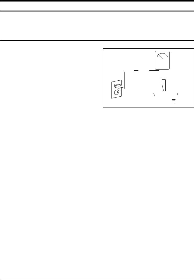
4.Leakage Current Hot Check (Figure 1-1): Warning: Do not use an isolation transformer during this test. Use a leakagecurrent tester or a metering system that complies with American National Standards Institute (ANIS C101.1, Leakage Current for Appliances), and Underwriters Laboratories (UL Publication UL1410, 59.7).
5.With the unit completely reassembled, plug the AC line cord directly into the power outlet. With the unit’s AC switch first in the ON position and then OFF, measure the current between a known earth ground (metal water pipe, conduit, etc.) and all exposed metal parts, including: antennas, handle brackets, metal cabinets, screwheads and control shafts. The current measured should not exceed 0.5 milliamp. Reverse the powerplug prongs in the AC outlet and repeat the test.
|
|
|
|
|
|
|
|
|
(READING SHOULD |
||
|
|
|
|
|
|
|
|
|
|||
|
|
|
|
|
|
LEAKAGE |
NOT BE ABOVE |
||||
DEVICE |
|
|
|
|
|
CURRENT |
|
0.5mA) |
|||
UNDER |
|
|
|
|
|
TESTER |
|
|
|
||
TEST |
|
|
|
|
|
|
|
|
|
|
|
|
|
|
|
|
|
|
|||||
|
|
TEST ALL |
|
|
|
|
|
|
|
||
|
EXPOSED METAL |
|
|
|
|
|
|
|
|||
|
|
SURFACES |
|
|
|
|
|
|
|
||
2-WIRE CORD |
|
|
|
|
|
|
|
||||
ALSO TEST WITH |
|
|
|
|
|
|
|
||||
PLUG REVERSED |
|
|
|
|
|
|
|
|
|||
(USING AC ADAPTER |
|
|
|
|
|
|
|
EARTH |
|||
PLUG AS REQUIRED) |
|
|
|
|
|
GROUND |
|||||
Fig. 1-1 AC Leakage Test
6.Antenna Cold Check:
With the unit’s AC plug disconnected from the AC source, connect an electrical jumper across the two AC prongs. Connect one lead of the ohmmeter to an AC prong. Connect the other lead to the coaxial connector.
7.X-ray Limits:
The picture tube is especially designed to prohibit X-ray emissions. To ensure continued X-ray protection, replace the picture tube only with one that is the same type as the original. Carefully reinstall the picture tube shields and mounting hardware; these also provide X-ray protection.
8.High Voltage Limits:
High voltage must be measured each time servicing is done on the B+, horizontal deflection or high voltage circuits. Correct operation of the X-ray protection circuits must be reconfirmed whenever they are serviced. (X-ray protection circuits also may be called “horizontal disable” or “hold-down”.)
Heed the high voltage limits. These include the X–ray Protection Specifications Label, and the Product Safety and X-ray Warning Note on the service data schematic.
1-1

Precautions
1-1 Safety Precautions (Continued)
9.High voltage is maintained within specified limits by close-tolerance, safety-related components and adjustments. If the high voltage exceeds the specified limits, check each of the special components.
10.Design Alteration Warning:
Never alter or add to the mechanical or electrical design of this unit. Example: Do not add auxiliary audio or video connectors. Such alterations might create a safety hazard. Also, any design changes or additions will void the manufacturer’s warranty.
11.Hot Chassis Warning:
Some TV receiver chassis are electrically connected directly to one conductor of the AC power cord. If an isolation transformer is not used, these units may be safely serviced only if the AC power plug is inserted so that the chassis is connected to the ground side of the AC source.
To confirm that the AC power plug is inserted correctly, do the following: Using an AC voltmeter, measure the voltage between the chassis and a known earth ground. If the reading is greater than 1.0V, remove the AC power plug, reverse its polarity and reinsert. Re-measure the voltage between the chassis and ground.
12.Some TV chassis are designed to operate with 85 volts AC between chassis and ground, regardless of the AC plug polarity. These units can be safely serviced only if an isolation transformer inserted between the receiver and the power source.
13.Some TV chassis have a secondary ground system in addition to the main chassis ground. This secondary ground system is not
isolated from the AC power line. The two ground systems are electrically separated by insulating material that must not be defeated or altered.
14.Components, parts and wiring that appear to have overheated or that are otherwise damaged should be replaced with parts that meet the original specifications. Always determine the cause of damage or overheating, and correct any potential hazards.
15.Observe the original lead dress, especially near the following areas: Antenna wiring, sharp edges, and especially the AC and high voltage power supplies. Always inspect for pinched, out-of-place, or frayed wiring. Do not change the spacing between components and the printed circuit board. Check the AC power cord for damage. Make sure that leads and components do not touch thermally hot parts.
16.Picture Tube Implosion Warning:
The picture tube in this receiver employs “integral implosion” protection. To ensure continued implosion protection, make sure that the replacement picture tube is the same as the original.
17.Do not remove, install or handle the picture tube without first putting on shatterproof goggles equipped with side shields. Never handle the picture tube by its neck. Some “in-line” picture tubes are equipped with a permanently attached deflection yoke; do not try to remove such “permanently attached” yokes from the picture tube.
18.Product Safety Notice:
Some electrical and mechanical parts have special safety-related characteristics which might not be obvious from visual inspection. These safety features and the protection they give might be lost if the replacement component differs from the original—even if the replacement is rated for higher voltage, wattage, etc.
Components that are critical for safety are indicated in the circuit diagram by shading,
(  ) or (
 ).
).
Use replacement components that have the same ratings, especially for flame resistance and dielectric strength specifications.
A replacement part that does not have the same safety characteristics as the original might create shock, fire or other hazards.
1-2 |
Samsung Electronics |

Precautions
1-2 Servicing Precautions
Warning1: First read the “Safety Precautions” section of this manual. If some unforeseen circumstance creates a conflict between the servicing and safety precautions, always follow the safety precautions.
Warning2: An electrolytic capacitor installed with the wrong polarity might explode.
1.Servicing precautions are printed on the cabinet. Follow them.
2.Always unplug the unit’s AC power cord from the AC power source before attempting to: (a) Remove or reinstall any component or assembly, (b) Disconnect an electrical plug or connector, (c) Connect a test component in parallel with an electrolytic capacitor.
3.Some components are raised above the printed circuit board for safety. An insulation tube or tape is sometimes used. The internal wiring is sometimes clamped to prevent contact with thermally hot components. Reinstall all such elements to their original position.
4.After servicing, always check that the screws, components and wiring have been correctly reinstalled. Make sure that the portion around the serviced part has not been damaged.
5.Check the insulation between the blades of the AC plug and accessible conductive parts (examples: metal panels, input terminals and earphone jacks).
6.Insulation Checking Procedure: Disconnect the power cord from the AC source and turn the power switch ON. Connect an insulation resistance meter (500V) to the blades of the AC plug.
The insulation resistance between each blade of the AC plug and accessible conductive parts (see above) should be greater than 1 megohm.
7.Never defeat any of the B+ voltage interlocks. Do not apply AC power to the unit (or any of its assemblies) unless all solid-state heat sinks are correctly installed.
8.Always connect a test instrument’s ground lead to the instrument chassis ground before connecting the positive lead; always remove the instrument’s ground lead last.
1-3
Precautions
1-3 Precautions for Electrostatically Sensitive Devices (ESDs)
1.Some semiconductor (“solid state”) devices are easily damaged by static electricity. Such components are called Electrostatically Sensitive Devices (ESDs); examples include integrated circuits and some field-effect transistors. The following techniques will reduce the occurrence of component damage caused by static electricity.
2.Immediately before handling any semicon ductor components or assemblies, drain the electrostatic charge from your body by touching a known earth ground. Alternatively, wear a discharging wrist-strap device. (Be sure to remove it prior to applying power— this is an electric shock precaution.)
3.After removing an ESD-equipped assembly, place it on a conductive surface such as aluminum foil to prevent accumulation of electrostatic charge.
4.Do not use freon-propelled chemicals. These can generate electrical charges that damage ESDs.
5.Use only a grounded-tip soldering iron when soldering or unsoldering ESDs.
6.Use only an anti-static solder removal device. Many solder removal devices are not rated as “anti-static”; these can accumulate sufficient electrical charge to damage ESDs.
7.Do not remove a replacement ESD from its protective package until you are ready to install it. Most replacement ESDs are packaged with leads that are electrically shorted together by conductive foam, aluminum foil or other conductive materials.
8.Immediately before removing the protective material from the leads of a replacement ESD, touch the protective material to the chassis or circuit assembly into which the device will be installed.
9.Minimize body motions when handling unpackaged replacement ESDs. Motions such as brushing clothes together, or lifting a foot from a carpeted floor can generate enough static electricity to damage an ESD.
CAUTION
These servicing instructions are for use by qualified service personnel only.
To reduce the risk of electric shock do not perform any servicing other than that contained in the operating instructions unless you are qualified to do so.
1-4 |
Samsung Electronics |
Specifications and IC Data
2. Specifications and IC Data
2-1 Specifications
Television System: |
|
MODEL |
|
SYSTEM |
|||
|
|
|
|||||
|
|
|
|
|
|
|
|
|
|
|
CT |
|
NTSC ONLY |
||
|
|
|
|
|
|
|
|
|
|
|
|
|
|
|
|
|
|
System |
|
|
|
NTSC |
|
|
|
|
Band |
|
|
|
|
|
|
|
|
|
|
|
|
Channels: |
|
|
VHF |
|
|
2 - 13 |
|
|
|
|
UHF |
|
|
14 - 69 |
|
|
|
|
CABLE |
|
|
1 - 125 |
|
Intermediate Frequencies (MHz) : |
|
|
|
|
|
|
|
|
SYSTEM |
|
|
|
|
||
|
|
|
|
|
|||
|
|
|
|
|
NTSC |
||
|
|
IF Carrier Frequency |
|
|
|
||
|
|
|
|
|
|
||
|
|
Picture IF Carrier |
|
|
45.75 |
||
|
|
Sound IF Carrier |
|
|
41.25 |
||
|
|
Color Sub Carrier |
|
|
42.18 |
||
Picture Tube: |
|
|
|
|
|
|
|
|
|
|
|
|
|
|
|
|
14 Inch |
A34KQV42X |
|
14Inch |
|||
|
|
|
|||||
|
|
15 Inch |
A36QDT351X |
|
15Inch Flat |
||
|
|
20 Inch |
A48KRD82X |
|
20Inch |
||
|
|
21 Inch |
A51KQJ63X |
|
21Inch |
||
|
|
|
|
|
|
|
|
|
|
|
|
|
|
|
|
Power Requirements: |
AC 120V, 60Hz |
Antenna Input Impedance: |
VHF, UHF : Telescopic dipole antenna (75 ohm unbalanced type ) |
Speaker Impedance |
8 ohm |
Samsung Electronics |
2-1 |
Specifications and IC Data
2-2 IC Line Up
Table 2-1 IC Line-Up
Loc. No |
Specificatio |
|
Description |
Remark |
|
|
|
|
|
||
IC201S |
SPM458AN |
TDA9377, English/Spanish/French |
Philips |
||
|
|
|
|
||
IC301 |
LA7840 |
VERTICAL OUTPUT |
Sanyo |
||
|
|
|
|
|
|
IC501 |
TDA6107Q |
RGB DRIVE AMP |
|
Philips |
|
|
|
|
|
|
|
IC602 |
TDA7266M/TDA7266S |
SOUND-AMP, |
TDA7266M (MONO) |
Philips |
|
TDA7266S (STEREO) |
|||||
|
|
|
|
||
|
|
|
|
|
|
IC801S |
KA5Q0740RT |
POWER IC (STR) |
|
FIAIR CHILD |
|
(0765RT) |
|
||||
|
|
|
|
||
IC802 |
KA7632 |
CUSTOM REGULATOR (5V, 8V, 3.3V) |
SEC |
||
|
|
|
|
|
|
IC202 |
24C04 |
EEPROM |
|
|
|
PC801S |
TCET1108 / LTV817B |
PHOTO COUPLER |
|
||
|
|
|
|
||
ICS601 |
UPC1851B |
Sound Processor (STEREO) |
NEC |
||
|
|
|
|
|
|
2-2 |
Samsung Electronics |
Specifications and IC Data
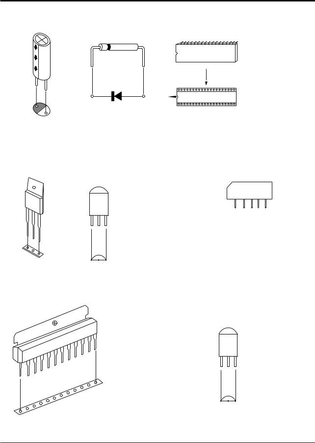
2-3 Semiconductor Base Diagrams
ELECTROLYTIC-
CONDENSER
TRANSISTOR
KSC5802
B
C
E
IC
DIODE
TRANSISTOR
KSC815-Y
KSA539-Y
E B C
LA7840
TDA6107Q
KA7632
IC
SPM458AN(Pin 64)
U4468B(Pin 16)
UPC851B(Pin 42)
SAW-FILTER
M1864M
1 |
1 |
1 |
|
TRANSISTOR
KSC2331-Y
E C B
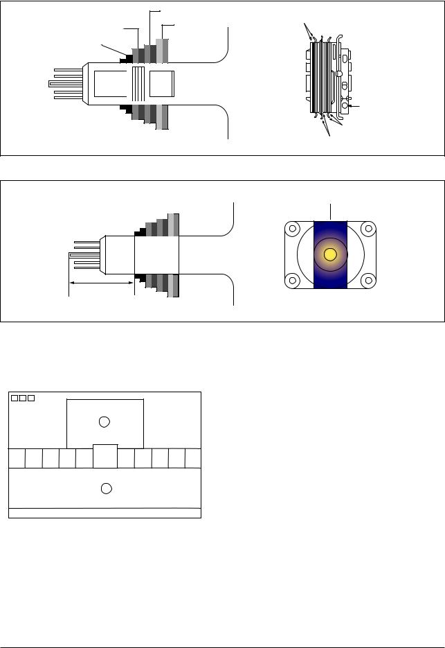
Fig. 2-1 Semiconductor Base Diagrams
Samsung Electronics |
2-3 |

MEMO
2-4
Disassembly and reassembly
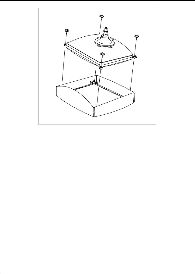
3. Disassembly and Reassembly
3-1 Back Cover Removal
1.After removing the screws, press the tension rib and pull the cabinet backwards.
2.To reassemble, press the tension rib (see diagram).
Samsung Electronics |
3-1 |

Disassembly and reassembly
3-2 Main Board Removal
1.Separate the socket board from the CRT neck.
2.Remove the Anode Cap from the CRT.
3.Remove the main board by pulling it with both hands.
Warning: The FBT is charged with high voltage. Before removing the Anode Cap, discharge the voltage through one of the heat sinks on the main board.
3-3 Speaker Removal
1. Remove the speaker by pressing the tension rib.
3-2 |
Samsung Electronics |
Disassembly and reassembly
3-4 CRT Removal
1.Spread a soft mat on the floor. Place the TV set face down.
2.Remove the 4 nuts mounting the CRT to the front cabinet. Lift the CRT.
3.Caution: Because of the high vacuum and large surface area of the picture tube, be careful while handling it: (1) Always lift the picture tube by grasping it firmly around the faceplate, (2) Never lift the tube by its neck. (3) Do not scratch the picture tube or apply excessive pressure. Fractures of the glass may cause an implosion.
Samsung Electronics |
3-3 |

MEMO
3-4 |
Samsung Electronics |
Alignment and Adjustments
4. Alignment and Adjustments
4-1 Preadjustment
4-1-1 Factory Mode
1.Do not attempt these adjustments in the Video Mode.
2.The Factory Mode adjustments are necessary when either the EEPROM (IC902) or the CRT is replaced.
3.Do not tamper with the “Adjustment” screen of the Factory Mode menu. This screen is intended only for factory use.
4-1-3 When CRT Is Replaced
1.Make the following adjustments AFTER setting up after setting up purity and convergence :
White Balance Sub-Brightness Vertical Center Vertical Size Horizontal Size
Fail Safe (This adjustment must be the last step).
4-1-2 When EEPROM (IC902) Is Replaced
1.When IC902 is replaced all adjustment data revert to initial values. It is necessary to re-program this data.
2.After IC902 is replaced, warm up the TV for 10 seconds.
2.If the EEPROM or CRT is replaced and set SC as 20(factory mode).
4-2 Factory/Service Mode
4-2-1 Procedure for the “Adjustment” Mode
1.This mode uses the standard remote control. The Service Mode is activated by entering the following remote-control sequence :
(1)DISPLAY → FACTORY.
(2)STAND-BY → MUTE → 1 → 8 → 2
→POWER ON.
4. Selection sequences for the all system:
DOWN or UP key:
SCT>SBT>BLR>BLB>RG>GG>BG>VSL>VS>
VA>HS>SC>CDL>STT>AKB>FS>NDL>
LBS>NSR>SCBT>VOL>CAP>HBS>RP00>
RP01>FMWS>AGC1>OMD>SCL>PWL>
MUS>AGC>DSK>DVDB
2.The “SERVICE (FACTORY)” message will be displayed. The Service Mode has four components: ADJUST, OPTION , G2-ADJUST and RESET.
3.Access the Adjustment Mode by pressing the “VOLUME” keys ( Up or Down). The adjustment parameters are listed in the accompanying table, and selected by pressing the CHANNEL keys ( ,
, ).
).
5.The VOLUME keys increase or decrease the adjustment values (stored in the
non-volatile memory) when Adjustment Mode is cancelled.
6.Cancel the Adjustment Mode by re-pressing the “FACTORY” or “Power OFF” keys.
Samsung Electronics |
4-1 |

Alignment and Adjustments
4-2-2 Main Adjustment Parameter
NO |
OSD |
|
|
|
FUNCTION |
|
RANGE |
INITAL DATA |
SETTING |
REMARK |
||||
|
|
|
|
|
|
|||||||||
|
|
|
|
19V |
13V |
|||||||||
|
|
|
|
|
|
|
|
|
|
|
|
|
||
1 |
SCT |
Su b |
Co n t ra s t |
|
0 |
~ |
23 |
15 |
13 |
13 |
W/B (HIGH Y) |
|||
|
|
|
|
|
|
|
|
|
|
|
|
|||
2 |
SBT |
Su b |
Br i g h t n e s s |
|
0 |
~ |
23 |
8 |
9 |
9 |
W/B A (LOW Y) |
|||
|
|
|
|
|
|
|
|
|
|
|
|
|
||
3 |
BLR |
Bl a c k |
Le v e l |
o f f se t |
Red |
0 |
~ |
6 3 |
35 |
31 |
31 |
W/B (LOW X, Y) |
||
|
|
|
|
|
|
|
|
|
|
|
|
|
||
4 |
BLB |
Bl a c k |
Le v e l |
o f f se t |
Blu e |
0 |
~ |
6 3 |
32 |
27 |
27 |
W/B (LOW X, Y) |
||
|
|
|
|
|
|
|
|
|
|
|
|
|
||
5 |
RG |
R e d |
G a i n |
|
|
0 |
~ |
6 3 |
40 |
32 |
32 |
W/B (HIGH X, Y) |
||
|
|
|
|
|
|
|
|
|
|
|
|
|||
6 |
GG |
G r e e n G a i n |
|
|
0 |
~ |
6 3 |
30 |
25 |
25 |
FIX |
|||
|
|
|
|
|
|
|
|
|
|
|
|
|
|
|
7 |
BG |
Bl u e |
|
G a i n |
|
|
0 |
~ |
6 3 |
42 |
31 |
31 |
W/B (HIGH X, Y) |
|
|
|
|
|
|
|
|
|
|
|
|
|
|||
8 |
VSL |
Ve r t i ca l |
S lo p e |
|
0 |
~ |
6 3 |
30 |
31 |
31 |
Vertical SLOPE |
|||
|
|
|
|
|
|
|
|
|
|
|
|
|||
9 |
VS |
Ve r t i ca l |
Sh i f t |
|
0 |
~ |
6 3 |
31 |
31 |
31 |
FIX |
|||
|
|
|
|
|
|
|
|
|
|
|
|
|||
10 |
VA |
Ve r t i ca l |
A m p l i t u d e |
|
0 |
~ |
6 3 |
20 |
40 |
20 |
Vertical SIZE |
|||
|
|
|
|
|
|
|
|
|
|
|
|
|||
11 |
HS |
H o r i z o n t a l |
Sh i f t |
|
0 |
~ |
6 3 |
32 |
30 |
30 |
Horizontal SHIFT |
|||
|
|
|
|
|
|
|
|
|
|
|
||||
12 |
SC |
S- Co r r e c t i o n |
|
0 |
~ |
6 3 |
35 |
20 |
12 |
FIX |
||||
|
|
|
|
|
|
|
|
|
|
|
|
|||
13 |
CD L |
Ca t h o d e |
D r i ve Le ve l |
|
0 |
~ |
1 5 |
11 |
11 |
7 |
FIX |
|||
|
|
|
|
|
|
|
|
|
|
|
|
|
||
14 |
ST T |
Su b |
T i n t |
|
|
0 |
~ |
7 |
3 |
7 |
7 |
FIX |
||
|
|
|
|
|
|
|
|
|
|
|
|
|
||
15 |
AKB |
A K B |
|
O n / o f f |
|
0 |
~ |
1 |
0 |
0 |
0 |
FIX |
||
|
|
|
|
|
|
|
|
|
|
|
|
|||
16 |
FS |
Filter Seting |
|
|
0 |
~ |
1 5 |
32 |
37 |
37 |
FIX(STEREO) |
|||
|
|
|
|
|
|
|
|
|
|
|
|
|
||
17 |
ND L |
NT SC |
De l a y |
|
|
0 |
~ |
1 5 |
1 |
1 |
1 |
FIX |
||
|
|
|
|
|
|
|
|
|
|
|
||||
18 |
LBS |
Low Band Separation Set |
|
0 |
~ |
6 3 |
32 |
32 |
32 |
FIX(STEREO) |
||||
|
|
|
|
|
|
|
|
|
|
|
|
|||
19 |
NSR |
N T SC |
Su b c o l o r |
|
0 |
~ |
2 3 |
3 |
3 |
3 |
FIX |
|||
|
|
|
|
|
|
|
|
|
|
|
||||
20 |
SCBT |
S c r e e n B r i g h r t n e s s |
|
0 |
~ |
6 3 |
35 |
45 |
45 |
FIX |
||||
|
|
|
|
|
|
|
|
|
|
|
|
|
||
21 |
VO L |
Vo l u m e |
p re |
s e t t i n g |
|
0 |
~ |
6 3 |
10 |
10 |
10 |
FIX |
||
|
|
|
|
|
|
|
|
|
|
|
|
|||
22 |
CAP |
C a p t i o n |
P o s i t i o n |
|
0 |
~ |
1 5 |
12 |
12 |
12 |
FIX |
|||
23 |
HBS |
H i g h B a n d S e p a r a t i o n S e t |
0 |
~ |
6 3 |
32 |
32 |
32 |
FIX(STEREO) |
|||||
|
|
|
|
|
|
|
|
|
|
|
||||
24 |
RP00 |
R a t i o P r e / o v e r s h o o t |
|
0 |
~ |
1 |
1 |
1 |
1 |
FIX |
||||
25 |
RP01 |
R a t i o P r e / o v e r s h o o t |
|
0 |
~ |
1 |
1 |
1 |
1 |
FIX |
||||
26 |
FMWS |
W i n d o w S e l e c t i o n S o u n d P L L |
0 |
~ |
1 |
0 |
0 |
0 |
FIX (Mono) |
|||||
27 |
AGC1 |
I F A G C S p e e d |
|
0 |
~ |
3 |
1 |
1 |
1 |
FIX (Nomal) |
||||
28 |
OMD |
O f f s e t I F D e m o d u l a t o r |
|
0 |
~ |
6 3 |
32 |
32 |
32 |
FIX (No Crrection) |
||||
29 |
SCL |
S o f t C l i p p i n g L e v e l |
|
0 |
~ |
3 |
3 |
1 |
1 |
FIX (Off) |
||||
30 |
PWL |
P e a k W h i t e L i m i t t i n g |
|
0 |
~ |
1 5 |
15 |
13 |
13 |
FIX (100%) |
||||
31 |
MUS |
M a t r i x U S A |
|
|
0 |
~ |
1 |
0 |
0 |
0 |
FIX (Mono) |
|||
|
|
|
|
|
|
|
|
|
|
|||||
32 |
AGC |
A u t o m a t i c G a i n C o n t r o l |
0 |
~ |
6 3 |
33 |
33 |
33 |
FIX |
|||||
|
|
|
|
|
|
|
|
|
|
|
||||
33 |
DSK |
D y n a m i c S k i n T o n e |
|
0 |
~ |
1 |
0 |
0 |
0 |
FIX |
||||
|
|
|
|
|
|
|
|
|
|
|
||||
34 |
DVDB |
D V D B r i g h t O f f s e t |
|
0 |
~ |
10 |
5 |
4 |
4 |
FIX |
||||
4-2 |
Samsung Electronics |
Alignment and Adjustments
4-2-3 Option Bytes
In the Service Mode, various can be selected via the Option Table. Example:
Option Table : xx xx
|
|
OSD |
SETTING |
REMARK |
|
|
|
|
|
|
|
|
|
VIDEO MUTE |
ON |
- 800msec Mute Time(Tri-norma) |
|
1 |
|
|
|||
(When swiching channel) |
OFF |
- Unavailable |
|||
|
|
|
|||
|
|
|
|
|
|
|
|
|
STEREO |
- Zenith stereo (WITH IN UPC1851B) |
|
|
|
|
|
||
2 |
AUDIO |
LINE STEREO |
- Line stereo (WITH IN UPC1851B) |
||
|
|
|
|
||
|
|
|
|
|
|
|
|
|
MONO |
- Mono (WITH OUT UPC1851B) |
|
|
|
|
|
|
|
3 |
|
ON |
- Stereo/L STEREO Model |
||
TURBO |
|
|
|||
OFF |
- Mono Model |
||||
|
|
||||
|
|
|
|||
|
|
|
|
|
|
4 |
|
ZOOM |
- Nornal / Zoom |
||
ZOOM |
|
|
|||
NOMAL |
- Nomal |
||||
|
|
|
|||
|
|
|
|
|
|
|
|
|
ON |
- The power is switched on automatically |
|
|
|
|
when detaching the Master S/W Auto On |
||
5 |
AUTO POWER ON |
|
|||
OFF |
- Tact S/W Model |
||||
|
|
||||
|
|
|
|||
|
|
|
|
|
|
|
|
SOUND MUTE |
OFF |
- Unavailable |
|
|
|
|
|
||
6 |
(NO SIGNAL) |
ON |
- Available |
||
|
|
|
|
|
|
|
|
|
ENGLISH |
|
|
7 |
LANGUAGE |
ESPANOL |
- Start Language Select |
||
|
|
||||
|
|
|
|||
|
|
|
FRENCH/PORTU |
|
|
8 |
|
OFF |
- Unavailable |
||
HOTEL MODE |
ON |
- Available |
|||
|
|
|
|||
|
|
|
AIR/STD/HRC/IRC |
|
|
9 |
CATV |
AIR/STD/HRC/AFN |
- U.S Army |
||
|
|
|
|||
|
|
|
ON |
- Available (U.S.A, Army) |
|
10 |
X-RAY |
OFF |
- Unavailable (South America) |
||
|
|
|
|||
|
|
|
ON |
- Available (U.S.A) |
|
11 |
V-CHIP |
OFF |
- Unavailable (Canada) |
||
|
|
|
|||
|
|
|
TV ↔ AV |
|
|
12 |
AV Option |
TV ↔ AV ↔ DVD |
|
||
|
|
|
|
||
|
|
|
ON |
- Available (South America) |
|
13 |
DEMO |
OFF |
- Unavailable (U.S.A) |
||
|
|
|
|||
Samsung Electronics |
4-3 |

Alignment and Adjustments
4-3 Other Adjustments
4-3-1 General |
4-3-2 Automatic Degaussing |
1.Usually, a color TV needs only slight touchup adjustment upon installation. Check the basic characteristics such as height, horizontal and vertical sync and focus.
2.The picture should have good black and white details. There should be no objectionable color shading; if color shading is present, perform the purity and convergence adjustments described below.
3.Use the specified test equipment or its equivalent.
4.Correct impedance matching is essential.
5.Avoid overload. Excessive signal from a sweep generator might overload the front-end of the TV. When inserting signal markers, do not allow the marker generator to distort test results.
6.Connect the TV only to an AC power source with voltage and frequency as specified on the backcover nameplate.
7.Do not attempt to connect or disconnect any wires while the TV is turned on. Make sure that the power cord is disconnected before replacing any parts.
8.To protect against shock hazard, use an isolation transformer.
A degaussing coil is mounted around the picture tube, so that external degaussing after moving the TV should be unnecessary. But the receiver must be properly degaussed upon installation.
The degaussing coil operates for about 1 second after the power is switched ON. If the set has been moved or turned in a different direction, disconnect its AC power for at least 30 minutes.
If the chassis or parts of the cabinet become magnetized, poor color purity will result. If this happens, use an external degaussing coil. Slowly move the degaussing coil around the faceplate of the picture tube and the sides and front of the receiver. Slowly withdraw the coil to a distance of about 6 feet before removing power.
4-4 |
Samsung Electronics |
4-3-3 High Voltage Check
CAUTION: There is no high voltage adjustment on this chassis. The B+ power supply must be set to +122.5 volts (Full color bar input and normal picture level).
1.Connect a digital voltmeter to the second anode of the picture tube.
2.Turn on the TV. Set the Brightness and Contrast controls to minimum (zero beam current).
3.The high voltage should not exceed 30KV.
4.Adjust the Brightness and contrast controls to
both extremes. Ensure that the high voltage does not exceed 30KV under any conditions.
4-3-4 FOCUS Adjustment
1.Input a black and white signal.
2.Adjust the tuning control for the clearest picture.
3.Adjust the FOCUS control for well defined scanning lines in the center area of the screen.
4-3-5 Cathode Voltage Adjustment
(Screen Adjustment)
1.Connect CRT socket pin GK to an oscilloscope probe.
2.Input a gray scale pattern. (Use a pattern generator, PM5518)
3.Use the P mode key (on the remote control) for the STANDARD picture.
4.Adjust the Screen VR (on the FBT) so that the voltage on the oscilloscope becomes 125+2.5V (See Fig. 4-1).
125 + 2.5V
GND
Fig. 4-1
Alignment and Adjustments
4-3-6 Purity Adjustment
1.Warm up the receiver for at least 20 minutes.
2.Plug in the CRT deflection yoke and tighten the clamp screw.
3.Plug the convergence yoke into the CRT and set in as shown in Fig. 4-2.
4.Input a black and white signal.
5.Fully demagnetize the receiver by applying an external degaussing coil.
6.Turn the CONTRAST and BRIGHTNESS controls to maximum.
7.Loosen the clamp screw holding the yoke. Slide the yoke backward or forward to provide vertical green belt. (Fig. 4-3).
8.Tighten the convergence yoke.
9.Slowly move the deflection yoke forward, and adjust for the best overall green screen.
10.Temporarily tighten the deflection yoke.
11.Produce blue and red rasters by adjusting the low-light controls. Check for good purity in each field.
12.Tighten the deflection yoke.
Samsung Electronics |
4-5 |
Alignment and Adjustments
|
4 Pole Magnet |
|
2 POLE |
|
PURITY |
6 Pole Magnet |
2 Pole Magnet |
|
|
Clamper |
|
Screw |
ADJU |
|
(VERT |
YOKE
CLAMP
SCREW
6 POLE CONVERGENCE
4 POLE CONVERGENCE
Fig. 4-2 Convergence Magnet Assembly
Vertical Green Belt
31m/m
1
2
Fig. 4-3 Center Convergence Adjustment
4-3-7 White Balance Adjustment
(a) Set up
1.Warm up the TV for at least 30 minutes in the Aging Mode (OSD White). This mode is displayed by entering the following sequence:
DISPLAY →FACTORY → FACTORY
2.Input a Toshiba pattern.
(b) Low-Light Adjustment
|
1. |
Set SBT to 1.2 fL in the Factory Service |
|
|
Mode with using CA100. See Fig. 4-4. |
Fig. 4-4 |
2. |
Adjust RG,BG so that the levels are suitable to |
|
||
|
|
each local area. |
|
(c) |
High-Light Adjustment |
|
1. |
Set SCT to 50FL(13V : 60FL) in the Factory |
|
|
Service Mode with using CA100. |
|
|
See Fig. 4-4 . |
4-6 |
Samsung Electronics |
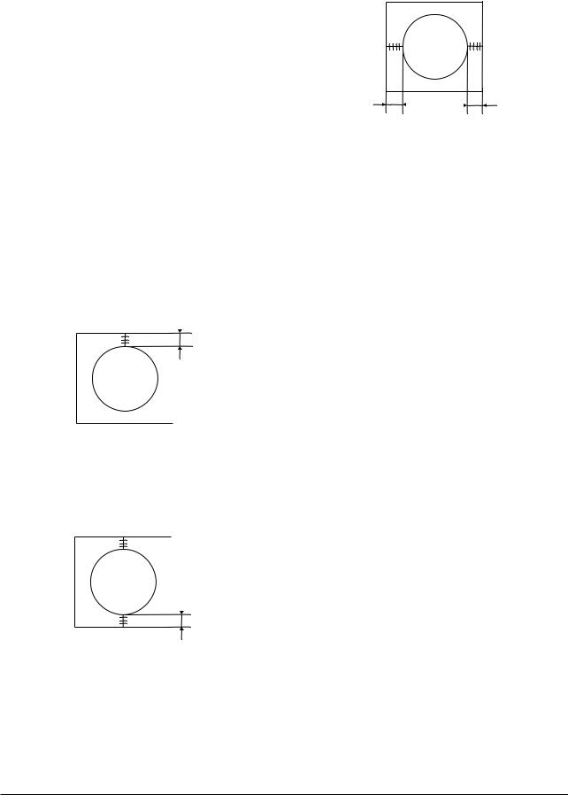
4-3-8 Center Convergence Adjustment
1.Warm up the receiver for at least 20 minutes.
2.Adjust the two tabs of the 4 pole magnets to change the angle between them. Superimpose the red and blue vertical lines in the center area of the screen.
3.Adjust the Brightness and Contrast controls for a well defined picture.
4.Adjust the two-tab pairs of the 4 pole magnets, and change the angle between them. Superimpose the red and the blue vertical lines in the center area of the screen.
Alignment and Adjustments
5.Turn the both tabs at the same time, keeping the angle constant, and superimpose the red and blue horizontal line in the center of the screen.
6.Adjust the two-tab pairs of the 6-pole magnets to superimpose the red and blue line onto the green. (Changing the angle affects the vertical lines, and rotating both magnets affects the horizontal lines.)
7.Repeat adjustments 2~6, if necessary.
8.Since the 4-pole magnets and 6-pole magnets interact, the dot movement is complex
(Fig. 4-5).
BLUE |
RED |
RED/BLUE |
GREEN |
|||||||
BLUE |
|
|
|
RED/BLUE |
|
|
|
|||
|
|
|
|
|
|
|||||
|
|
|
|
|
|
|||||
RED |
|
|
|
GREEN |
|
|
|
|||
|
|
|
|
|
|
|
|
|
|
|
4-Pole Magnet Movement |
6-Pole Magnet Movement |
|||||||||
Fig. 4-5 Center Convergence Adjustment
Samsung Electronics |
4-7 |
Alignment and Adjustments
4-3-9 RF AGC Adjustment
Set the AGC data to 33 (Factory Mode).
4-3-10 Sub-Color Adjustment
Set NSR data to 3 (Factory Mode).
4-3-11 Geometry Adjustment
SC →VS→VA→VSL→HS
1.Input a lion head pattern.
2.Set the SC (S-Correction) as 20(13V : 12) and VS(Vertical Shift) 31 so that the lion head circle becomes oval.
3.Adjust with VA (Vertical Amplitude) so that the top margin of the picture is 4.
4
Fig. 4-7
4.Adjust with VSL (Vertical-Slope) so that the bottom margin of the picture is 4.
4
Fig. 4-8
5.Adjust with HS (Horizontal Shift) so that the lion-head pattern and CRT centers are aligned.
5 |
5 |
Fig. 4-9
6.Adjust HS (Horizontal Shift) so that the left and right margins of the picture are 5.
4-8 |
Samsung Electronics |

Troubleshooting
5. Troubleshooting
5-1 No Power
Counect the Power code
Check the |
|
Normal |
|
Check the |
Normal |
|
Check the |
Abnormal |
||||||
|
|
3.3V-A,5V-A Line |
|
|
X-tal,SDA,SCL |
port |
|
|
||||||
|
|
|
|
|
|
|
||||||||
12.5V-A Line |
|
|
|
of IC201S |
|
|
of IC201S |
|
|
|||||
|
|
|
|
|
|
|
|
|
|
|
|
|
|
|
Abnormal |
|
|
|
|
|
|
|
|
|
Normal |
|
|
|
|
|
|
|
|
|
|
|
|
|
|
|
|
|
||
|
|
|
|
|
|
|
|
|
|
|
|
|
||
|
|
|
|
Abnormal |
|
|
|
|
|
|
Replace |
|||
|
|
|
|
|
|
|
|
|
|
|
||||
|
|
|
|
|
|
|
|
|
|
|
|
IC201 S |
||
|
|
|
|
|
|
|
|
|
|
|
|
|
||
Check the |
|
|
|
|
|
|
|
|
|
|
|
|
|
|
|
|
|
|
|
|
|
|
|
|
|
|
|
||
FD801S, D807, IC801S |
|
|
|
|
|
|
|
|
Check the |
|
|
|||
or AC-Fuse |
|
|
|
Check/Replace |
|
|
|
|
|
|||||
|
|
|
|
|
IC802 |
|
|
|
(33)Pin (H-Drive) |
|
|
|||
|
|
|
|
|
|
|
||||||||
|
|
|
|
|
|
|
|
|
||||||
|
|
|
|
|
|
|
|
|
|
of IC201S |
Abnormal |
|||
|
|
|
|
|
|
|
|
|
||||||
|
|
|
|
|
|
|
|
|
|
|
|
|
|
|
|
|
|
|
|
|
|
|
|
|
Normal |
|
|
|
|
|
|
|
|
|
|
|
|
|
|
|
|
|
Abnormal |
|
|
|
|
|
|
|
|
|
|
|
Check the |
|
|||
|
|
|
|
|
|
|
|
|
|
|
|
|||
|
|
|
|
|
|
|
|
|
|
122.5V- A Line |
|
|
||
|
|
|
|
|
|
|
|
|
|
|
|
|
|
|
|
|
|
|
|
|
|
|
|
|
|
|
|
|
|
|
|
|
|
|
|
|
|
|
|
|
|
|
|
|
|
|
|
|
|
|
|
|
|
|
Normal |
|
|
Check the |
|
|
|
|
|
|
|
|
|
|
|
|
FBT,D805(D806) |
|||
|
|
|
|
|
|
|
|
|
|
|
|
|
|
|
|
|
|
|
|
|
|
|
|
|
|
|
|
|
|
|
|
|
|
|
|
|
|
|
|
|
|
|
||
|
|
|
|
|
|
|
|
|
|
Check / Replace |
|
|
||
|
|
|
|
|
|
|
|
|
|
Q401 |
|
|
||
|
|
|
|
|
|
|
|
|
|
|
|
|
|
|
Samsung Electronics |
5-1 |

Troubleshooting
5-2 No Video (Sound OK)
Check RK,GK,BK |
Abnormal |
Check R,G,B |
Nornal |
Check IC501 |
|
Signal into CRT |
|
B+(180V-B) |
|
Signal |
|
|
|
|
|
PCB |
|
|
|
|
|
|
|
|
Nornal |
|
|
|
|
|
|
|
|
Abnormal |
Check the |
Abnormal |
|
|
|
|
|
|
|
|
Voltage of heater |
|
|
|
|
|
|
Abnormal |
|
|
|
|
|
|
Check the |
|
Check/Replace |
|
|
resistance of R420 |
Nornal |
|
|
|
|
R421,R422,D505 |
|
|
|
|
|
|
|
|
Nornal
Check
CRT and FBT
Abnormal |
Check IC201S |
Check/Replace |
|
Pin 51,52,53 |
D812,FBT |
|
(R.G.B) |
|
Check/Replace |
Nornal |
|
IC201S |
|
|
|
Check IC201S |
|
|
Pin 49(BCL-IN) |
|
Abnormal |
Pin50(IK) |
|
|
Nornal |
|
|
Check |
|
|
CRT and FBT |
|
Nornal
Re-Adjust
Screen Voltage
Abnormal
Replace
R420
5-2 |
Samsung Electronics |
 Loading...