


LED TV
Installation manual
Thank you for purchasing Samsung product. To receive more service, please register your product at
www.samsung.com/register
Model |
Serial No. |
Figures and illustrations in this User Manual are provided for reference only and may differ from actual product appearance. Product design andspecifications maybe changedwithout notice.
Instruction
This TVis providedwith interactivefunctionalitythrough a set-back box (SBB/STB) connectedtothe TV, andwith otherTVs in a computercontrolled systemforhotels and otherhospitalitybusinesses.
Interactive:Whenthe TVis powered-up initially, it sends a commandto identifythe SBB/STB; if identified,the TVswitchesto ONLINEmode andfull control isthroughthe SBB/STB.
Ifthe TVis in ONLINE mode, it stops receiving IR(Samsung remote) commands and acts accordingto interface protocol. Stand-Alone: If SBB/STB is not identified,the TVshould be switchedto STAND-ALONE modewith restricted operation.
Operational Modes
Whenthis TV(in Hotel mode) is operatedwith a SBB/STB,it is in one oftwo states :
•• ONLINE orSTAND-ALONE. Inthe STAND-ALONE state,the TVwill act as a Hotel TV,butwithout active communication. This isto prevent guestsfromtryingto cheatthe system bydisconnectingthe SBB/STB.
Hotel TV |
Stand-alone Mode |
|
Hotel Mode On |
SBB/STB Online if |
|
one success within |
|
|
|
|
|
|
10 attempts |
|
Power |
SBB/STB Online-10 |
SBB/STB Status- |
ON |
||
|
consecutive fails |
Attempt every2secs |
Online Mode
Poll Rate 20/sec
To setthe detailsforStand-alone orinteractive mode, referto pages 28-33(Settingthe hotel option data : Stand-alone mode and Interactive mode)
•• Some operations maybe restrictedto prevents guestsfrom "cheating"the TVsystem.
•• Nomain menu(Interactive mode) orChannel Menu, Plug & Playin Main Menu (Stand-Alone mode)
•• LimitedVolume and Panel keylock orunlock
Still image warning
Avoid displaying still images (like jpeg picturefiles) orstill image element (like TVProgram logo, panoramaor4:3 imageformat, stock or news barat screen bottom etc.)onthe screen. Constant displaying of still picture can cause unevenwearof screen phosphor,whichwill affect image quality. To reduce risk ofthis effect, pleasefollowbelowrecommendations:
•• Avoid displayingthe same TVchannelforlong periods.
•• Alwaystrydo displayanyimage onfull screen, use TVset pictureformat menuforbest possible match.
•• Reduce brightness and contrastvaluesto minimum requiredtoachieve desired picture quality, exceededvalues mayspeed upthe burnout process.
•• Frequentlyuse all TVfeatures designedto reduce image retention and screen burnout. Refertothe relevant usermanual sectionfor details.
Securing the Installation Space
Keep required distancesbetweenthe product and otherobjects (e.g.walls)to ensure properventilation. Failingto do so mayresult infire ora problemwiththe product dueto an increase inthe internaltemperature.
•• When using a stand orwall-mount,use parts providedbySamsung Electronics only.
‒‒ Using parts provided byanothermanufacturermayresult in a problemwiththe product orinjuries duetothe productfalling.
•• The appearance may differ, depending on the product. |
|
Installation with a stand. |
Installation with a wall-mount. |
 10 cm
10 cm
10 cm |
10 cm |
|
10 cm |
10 cm |
10 cm |
|
10 cm |

Contents
•• |
Accessories.................................................................................................................................................................... |
4 |
•• Installingthe LED TVStand........................................................................................................................................ |
5 |
|
•• Assemblingtheswivel (32inch TVs orlarger)........................................................................................................ |
8 |
|
•• Viewingthe Connection Panel................................................................................................................................... |
10 |
|
•• |
TVController.................................................................................................................................................................. |
14 |
•• Viewingthe Remote Control...................................................................................................................................... |
16 |
|
•• Samsung Smart Control(sold separately)............................................................................................................... |
18 |
|
•• |
Connectingthe TVwith SBB....................................................................................................................................... |
21 |
•• Connectingthe Bathroom Speakers......................................................................................................................... |
22 |
|
•• Connectingthe MediaHub HD.................................................................................................................................... |
24 |
|
•• Connectingthe RJP(Remote Jack Pack).................................................................................................................. |
25 |
|
•• Connectingto a COMMON INTERFACEslot (YourTVviewing CardSlot)........................................................... |
27 |
|
•• Settingthe Hotel Option Data.................................................................................................................................... |
28 |
|
•• |
Installing the Wall Mount............................................................................................................................................ |
72 |
•• Securing the TV to the Wall......................................................................................................................................... |
73 |
|
•• |
Anti-theft Kensington Lock........................................................................................................................................ |
73 |
•• |
Specifications................................................................................................................................................................ |
74 |
•• |
Dimensions.................................................................................................................................................................... |
75 |
•• |
Licence............................................................................................................................................................................ |
78 |
ENGLISH
English 3

Accessories
Please make sure the following items are included with your LED TV. If any items are missing, contact yourdealer.
The items’ colour and shapes may vary depending on the model.
•• |
Remote Control & Batteries (AAAx 2) |
•• |
Hotel Mount Kit (32 inch TVs orlarger) |
|
•• |
Samsung Smart Control (soldseparately) (32 inch TVs |
•• |
PowerCord/ Data Cable |
|
|
orlarger) |
•• |
Owner’s Instructions |
|
•• |
Quick Setup Guide |
|||
|
SafetyGuide(Not available in all locations) |
|||
•• |
CICardAdapter |
•• |
Cable Holder |
4EA
Wall mount Adapter
The stand andstand screw may not be included, depending on the model.
The Data Cable may not be included, depending on the SI Vendor.
Correct Disposal of This Product (Waste Electrical & Electronic Equipment)
(Applicable in the European Union and other European countries with separate collection systems)
This marking on the product, accessories or literature indicates that the product and its electronic accessories (e.g. charger, headset, USB cable) should not be disposed ofwith otherhouseholdwaste atthe end oftheirworkinglife. To prevent possible harmtothe environment orhuman healthfrom uncontrolled waste disposal,please separatethese itemsfrom othertypes ofwaste and recyclethem responsiblyto promotethesustainable reuse ofmaterial resources. Householdusers should contact eitherthe retailer wheretheypurchasedthis product,ortheirlocal governmentoffice,fordetailsofwhere and howtheycan takethese itemsforenvironmentallysafe recycling. Business users shouldcontacttheirsupplierand check theterms and conditionsofthe purchase contract. This product and itselectronic accessories shouldnot be mixedwith othercommercialwastesfordisposal.
Correct disposal of batteries in this product
(Applicable in the European Union and other European countries with separate battery return systems.)
This marking onthe battery, manual orpackaging indicatesthatthe batteries inthis product should not be disposed ofwith otherhouseholdwaste atthe end oftheirworking life.Where marked,the chemical symbols Hg, Cd orPb indicatethatthe batterycontains mercury, cadmium orlead abovethe reference levels in EC Directive2006/66. If batteries are not properlydisposed of,these substances can cause harm to human health or the environment. To protect natural resources and to promote material reuse, please separate batteriesfrom othertypes ofwaste and recyclethemthroughyourlocal,free batteryreturn system.
4 English

Installing the LED TV Stand
The 32”andlargerLED TVs have swivel stands. You can setthese stands sothatthe TVs swivel 20 degrees left and rightor 90 degrees left and right.
Stand Components
When installing the stand, use the provided components and parts.
|
|
|
|
|
C |
24" |
|
B |
1 EA |
|
|
x3 (M4 x L12) |
|
A 1EA |
|
|
|
|||
|
|
|
|
|
|
|
|
|
|
|
|
D |
28" |
|
|
|
|
|
|
|
|
|
|
|
|
|
x7 (M4 x L12) |
24" |
28"~55" |
28" |
32" |
40"~55" |
E |
32" x7 (M4 x L12) |
|
|
|
|
|||
|
|
|
|
|
|
|
|
|
|
|
|
|
40"~55" x8 (M4 x L12) |
|
Stand |
|
Guide Stand |
|
|
Screws |
HG24EE690
1 |
2 |
3 |
4 |
x3 (M4 X L12) |
|
B |
English 5

HG28EE690
1
|
|
D |
|
|
|
x4 (M4 X L12) |
|
|
|
B |
|
|
A |
|
|
ATTENTION |
|
|
|
DO NOTUSE |
DONOTUSE |
DONOT |
|
CHEMICALS |
GREASE |
USEOIL |
|
2 |
|
|
Side View |
|
|
Place a soft cloth over the table to |
(Correct assembly) |
|
|
|
|
|
|
protect the TV, and then place the |
|
|
|
TV on the cloth screen-side down. |
|
Insert the Stand Guide into the slot on the bottom ofthe TV.
(Incorrect assembly)
3 |
4 |
D |
x4 (M4 X L14) |
Whenyouencountera slope,tryreassemblefrom
Step 2.
Fix the stand guide on the TV not to be moved.
Progress the assembly of screw in the manual’s order.
6 English
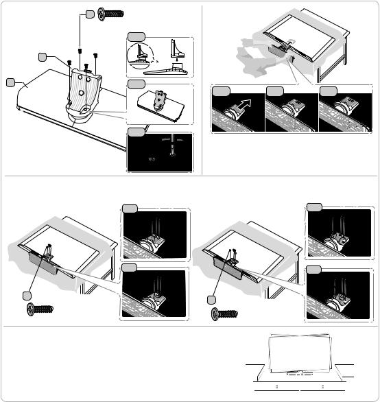
HG32EE690 / HG40EE690 / HG49EE690 / HG55EE690
1 |
E |
x4 |
2 |
|
|
||
|
|
(M4 X L12) |
|
|
|
1-1 |
|
|
B |
|
|
A |
|
1-2 |
|
2-1 |
2-2 |
2-3 |
1-3
 Place a soft cloth over the table to protect the TV, and then
place the TV on the cloth screen-side down.
Insert the Stand Guide into the slot on the bottom of the TV.Slide and assemble it to the endline in the direction of arrow.
3 Tightthe bottom screwfirst,and upperscrewlast.
Progress the assembly of screw in the manual’s order.
3-1 |
3-1 |
|
3-2 |
3-2 |
E 32" |
E |
40" ~ 55" |
|
||
|
x3 (M4 x L12) |
x4 (M4 x L12) |
|
|
4 Whenthe declination happened,tryreassemble it 2category.
Make sure to assembling stand guide attached onthe TV.
NOTE
•• Makesureto distinguishbetweenthefront and back of each componentwhen assemblingthem.
•• Make sure that at least two persons lift and move the TV.
English 7
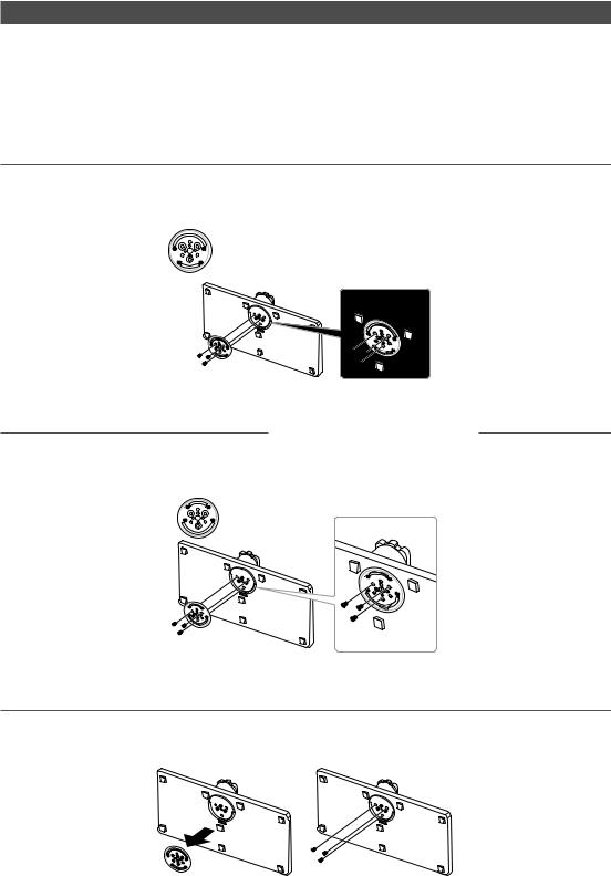
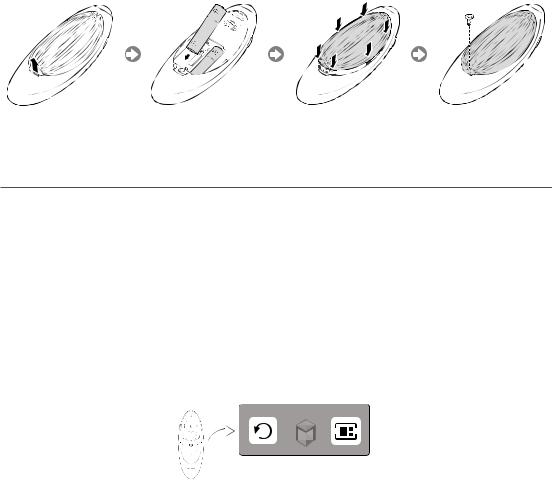
Assembling the swivel (32 inch TVs or larger)
]]WARNING: Ifyou configurethe TVto swivel,you must attach itsecurelytothefloor, a desk, a dressertop, etc. as
describedinthe installation instructions.
The 32”andlargerLED TVs have swivel stands. You can configurethese stands sothatthe TVs swivel 20 degrees left and right, 60 degrees left andright, or90 degrees left and right usingthe BRACKETHOLDER SWIVEL.
¦¦20° Swivel
To configurethe TVsothat itswivels 20° leftand right, insertthe prong onthebottom ofthe standthroughthe curved hole inthe Bracket HolderSwivel marked 20°. Then,fixthe Bracket HolderSwiveltothe stand usingthethree supplied screws as shown below.
¦¦60° Swivel
To configurethe TVsothat itswivels 60° left andright,insertthe prong onthe bottom ofthe standthroughthe curved hole inthe Bracket HolderSwivel marked 60°. Then,fixthe Bracket HolderSwiveltothestandusingthethree supplied screws as shown below.
¦¦90° Swivel
To configurethe TVsothat itswivels 90° left andright,removethe Bracket HolderSwivel, andthen screwthethree supplied screws intothe stand as shown below.
8 English

¦¦Hotel Mount Kit
Bolt + Nut
Short Bolt (2EA) |
Long Bolt (2EA) |
Nut (2EA) |
Washer(2EA) |
Top
Bottom |
Affixthe standto aflat surface such as a dresser |
top, desk top, or entertainment centre as shown. |
[ WARNING: To prevent injury,you must attachthis TVsecurelytothefloor, atable, a dressertop, etc.with
the Hotel Mount Kit as describedinthese instructions.
English 9

HG24EE690**
HG28EE690**
HG32EE690**
HG40EE690**
HG49EE690**
HG55EE690**
Viewing the Connection Panel
4

2

^
1
2
3
5
!
0
2
3
7
$
5
$ 3 % # 7
6 5 8 9
% $
|
HDMI IN 3 |
|
(DVI) |
|
DIGITAL |
3 |
AUDIO OUT |
HDMI IN 2 (OPTICAL) |
|
(ARC) |
|
|
# |
6 |
@ |
|
|
7 |
! |
|
|
8 |
|
9 0
3 % 1
HDMI IN 3 (ARC)
LAN OUT |
9 |
|
^
#


 8
8
@
6
10 English
Whenever you connect an external device to your TV,make sure that power on the unit is turnedoff.When connectingan external device, match the colour of the connection terminal to the cable.
1 AV IN
‒‒ Connect audio cables to "[L-AUDIO-R]" onyourTVand the otherends to corresponding audio out jacks on anA/V device.
‒‒ Connect RCA audio cables (optional) to "[L-AUDIO-R]" on the rear of the TV set and the other ends to corresponding audio out jacks onthe external device.
‒‒ When connecting to AV IN, the colour of the AV IN [Y/VIDEO] jack (Green) does not match the colourof thevideo cable (Yellow).
2 USB (5V 0.5A), USB (HDD/1.0A) / CLONING
‒‒ Connectorforsoftware upgrades and Media Play, etc. ‒‒ Service connection.
3HDMI IN / HDMI IN (ARC) / HDMI IN (DVI)
Connectstothe HDMI jack ofa devicewith an HDMI output.
Nosoundconnection is needed for an HDMI-HDMI connection. HDMI connections carry both audio and video.
Use the HDMI IN (DVI) jack for a DVI connectionto an external device. Use a DVI to HDMI cable or DVI-HDMI adapter (DVI to HDMI) forthe video connection andthe PC/DVI AUDIO IN jacks for audio.
4LAN
Connectto awired LANusing CAT7 cable.
5ANT IN (SATELLITE), (AIR/CABLE)
‒‒ To view television channels correctly, the TV must receive a signal from one of the following sources:
‒‒ An outdoorantenna /Acabletelevision system
6HEADPHONE JACK
Headphones maybe connectedtothe headphone jack onyourTV.Whilethe headphones are connected,the sound fromthe built-in speakers is disabled.
7RJP
This port is anRJP(Remote Jack Pack) communication portthat enables connecting different devicesto additional modules to improve device use and convenience.
8PC/DVI AUDIO IN
Connectstothe audio out jack of an external DVI device using a1/8th inch stereo phone jack cable. Some DVI devices may not or should not need this connection audio.
9PC IN
Connecttothevideo output jackonyourcomputer.
0VOL-CTRL
Usedto controlthevolume ofthe Bathroom speaker. ConnecttheBathroomWall Box andtheVOLCTRLport.
!VARIABLE AUDIO OUT
Usedfortheaudio outputtothe Bathroom speaker. Connectthe BathroomWall Box andtheVariable port (RCA).
@CLOCK
Setthetime afterconnectingthe cable ofthe External Clockto Clock jack. You can usethe External Clock Display function.
# DATA
‒‒ Usedto support data communication betweenthe TVandthe SBB.
‒‒ Connects using RJ-12 TVtype plugs.
$ DIGITAL AUDIO OUT (OPTICAL)
Connectsto a DigitalAudio component.
English 11

%HP-ID
Connectthe cableto HP-ID and Headphone Jack simultaneouslyandconnect itto separatedHeadphone Box.See page 23.When connecting Headphoneto Headphone Box, itworks same as Headphonefunction.
^LAN OUT
WiredLAN connection port usedto connect an external device such as a laptopto connecttothe Internet.(However, the TVmust be connectedtothe Internetviawired LAN.)
Display Modes
You can also select one ofthe standard resolutions listedinthe Resolution column. The TVwill automaticallyadjusttothe resolution you choose.
AfterconnectingacomputertotheTV,setthescreenresolutionfortheTVonthecomputer. Theoptimal resolutionis1920 x1080 @ 60 Hz. Ifit is setto anyotherthan inthetable below,the TVmaydisplaynothing. Setthe resolution properly, referring to the user guide of the computer or its graphic card.
The resolutions inthetable are recommended.
Optimal resolution is 1366 X 768 @ 60 Hz.
Mode |
Resolution |
Horizontal Frequency |
Vertical Frequency (Hz) |
Pixel Clock Frequency |
Sync Polarity (H / V) |
|
(KHz) |
(MHz) |
|||||
|
|
|
|
|||
IBM |
640 x 350 |
31.469 |
70.086 |
25.175 |
+/- |
|
720 x 400 |
31.469 |
70.087 |
28.322 |
-/+ |
||
|
||||||
MAC |
640 x 480 |
35.000 |
66.667 |
30.240 |
-/- |
|
832 x 624 |
49.726 |
74.551 |
57.284 |
-/- |
||
|
||||||
VESA CVT |
720x 576 |
35.910 |
59.950 |
32.750 |
-/+ |
|
1280 x 720 |
56.456 |
74.777 |
95.750 |
-/+ |
||
|
640 x 480 |
31.469 |
59.940 |
25.175 |
-/- |
|
|
640 x 480 |
37.500 |
75.000 |
31.500 |
-/- |
|
|
640 x 480 |
37.861 |
72.809 |
31.500 |
-/- |
|
|
800 x 600 |
37.879 |
60.317 |
40.000 |
+/+ |
|
|
800 x 600 |
46.875 |
75.000 |
49.500 |
+/+ |
|
VESA DMT |
800 x 600 |
48.077 |
72.188 |
50.000 |
+/+ |
|
|
1024 x 768 |
48.363 |
60.004 |
65.000 |
-/- |
|
|
1024 x 768 |
56.476 |
70.069 |
75.000 |
-/- |
|
|
1024 x 768 |
60.023 |
75.029 |
78.750 |
+/+ |
|
|
1280 x 720 |
45.000 |
60.000 |
74.250 |
+/+ |
|
|
1366 x 768 |
47.712 |
60.015 |
85.500 |
+/+ |
|
VESA GTF |
1280 x 720 |
52.500 |
70.000 |
89.040 |
-/+ |
12 English

Optimal resolution is 1920 X 1080 @ 60 Hz.
Mode |
Resolution |
Horizontal Frequency |
Vertical Frequency (Hz) |
Pixel Clock Frequency |
Sync Polarity |
|
(KHz) |
(MHz) |
(H / V) |
||||
|
|
|
||||
IBM |
720 x 400 |
31.469 |
70.087 |
28.322 |
-/+ |
|
|
640 x 480 |
35.000 |
66.667 |
30.240 |
-/- |
|
MAC |
832 x624 |
49.726 |
74.551 |
57.284 |
-/- |
|
|
1152 x 870 |
68.681 |
75.062 |
100.000 |
-/- |
|
|
640 x 480 |
31.469 |
59.940 |
25.175 |
-/- |
|
|
640 x 480 |
37.861 |
72.809 |
31.500 |
-/- |
|
|
640 x 480 |
37.500 |
75.000 |
31.500 |
-/- |
|
|
800 x 600 |
37.879 |
60.317 |
40.000 |
+/+ |
|
|
800 x 600 |
48.077 |
72.188 |
50.000 |
+/+ |
|
|
800 x 600 |
46.875 |
75.000 |
49.500 |
+/+ |
|
|
1024 x 768 |
48.363 |
60.004 |
65.000 |
-/- |
|
|
1024 x 768 |
56.476 |
70.069 |
75.000 |
-/- |
|
|
1024 x 768 |
60.023 |
75.029 |
78.750 |
+/+ |
|
VESA DMT |
1152 x 864 |
67.500 |
75.000 |
108.000 |
+/+ |
|
1280 x1024 |
63.981 |
60.020 |
108.000 |
+/+ |
||
|
||||||
|
1280 x1024 |
79.976 |
75.025 |
135.000 |
+/+ |
|
|
1280 x 720 |
45.000 |
60.000 |
74.250 |
+/+ |
|
|
1280 x 800 |
49.702 |
59.810 |
83.500 |
-/+ |
|
|
1280 x 960 |
60.000 |
60.000 |
108.000 |
+/+ |
|
|
1366 x 768 |
47.712 |
60.015 |
85.500 |
+/+ |
|
|
1440 x 900 |
55.935 |
59.887 |
106.500 |
-/+ |
|
|
1600 x 900RB |
60.000 |
60.000 |
108.000 |
+/+ |
|
|
1680x1050 |
65.290 |
59.954 |
146.250 |
-/+ |
|
|
1920 x1080 |
67.500 |
60.000 |
148.500 |
+/+ |
When using an HDMI/DVI cable connection, you must use the HDMI IN (DVI) jack.
The interlace mode is not supported.
The set mightoperate abnormally if a non-standard video format is selected.Separate and Composite modes are supported. SOG is not supported.
English 13
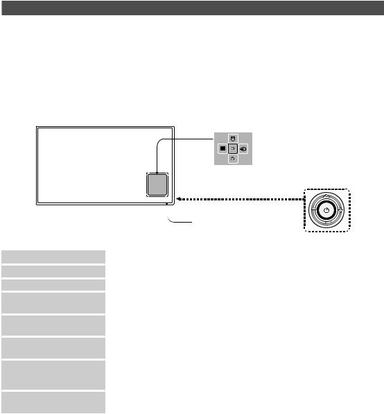
TV Controller
TVControlleris a multi directional buttonthathelps navigatewithout usingthe remote control.Some functions which require a PIN code may not be available.
The product colour and shape may vary, depending on the model.
Exits the menu when pressing the controller for more than 1 second.
When selecting the function by moving thecontroller tothe up/down/left/right directions, do not press the controller. If the controller is used first, you cannot operate it to move the up/down/left/right directions.
HG24EE690 / HG28EE690
|
|
|
|
|
Function menu |
||
|
|
|
TV Controller |
|
The image is drawn byfacingthefront side |
||
|
|
|
of the TV. |
|
Remote control sensor |
||
Power on |
Turnthe TVon bypressingthe controllerin standbymode. |
||
Adjusting the volume |
Adjustthevolume bymovingthe controllerfrom sideto sidewhenthe poweris on. |
||
Selecting a channel |
Select a channel bymovingthe controllerup and downwhenthe poweris on. |
||
Using the function menu |
Press the controller when the power is on and the function menu appears. If you press |
||
|
it again, the function menu screen disappears. |
||
Using the Menu
Selecting the Source
Selecting the SMART HUB
( ™)
Selects the MENU(m) bymovingthe controllerinthefunction menu screen.The OSD(On Screen Display) ofyourTV’sfeature appears.
Selects the Source(s) bymovingthe controllerinthefunction menu screen. The
Source list screen appears.
Withthe Functionmenuvisible, select SMART HUB (™) bymovingthe Controller upwards. The SMART HUB main screen appears. Select an application bymovingthe Controller, andthen pressingthe Controller.
Power Off |
Selects the Power Off(P)toturnthe TVoff bymovingthe controllerinthefunction |
|
menu screen. |
To close the Menu, SMART HUB, or Source, press the Controller formore than 1 second.
14 English
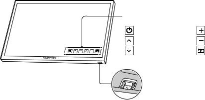
HG32EE690 / HG40EE690 / HG49EE690 / HG55EE690
The TV's Controller, a small joy stick like button on thebottom right side of the TV,letsyou control the TV without
the remote control.
Control Menu |
|
: Power Off |
: Volume Up |
: Channel Up |
: Volume Down |
: Channel Down |
: Source |
TV Controller / Remote control sensor
Press: Move
Press & Hold: Select
The TV Controller isplaced atthe bottom ofthe TV.
Standby mode
Do not leaveyourproduct in standbymodeforlong periods oftime (whenyou are awayon a holiday,forexample).Asmall amount of electric poweris still consumedevenwhenthe powerbutton isturned off.
English 15
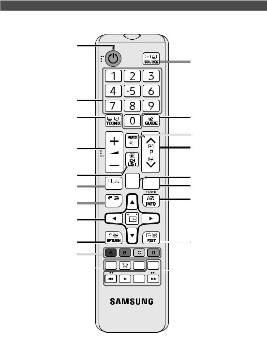
Viewing the Remote Control
This remote control has Braille points onthe Power, Channel, and Volume buttons and can be used by visually
impaired persons.
Turns the TV on and off.
Displayand select availablevideo sources.
Have direct accessto channels. |
|
|
|
Alternatelyselects Teletext, Double |
|
|
Electronic ProgrammeGuide (EPG) |
orMix. |
|
|
display. |
|
|
|
Cut offthe soundtemporarily. |
Adjustthevolume. |
|
|
Change channels. |
|
|
|
|
Displaychannel list onthe screen. |
|
|
Switchtothe HOMEScreen. |
|
|
|
|
Displaythe main on-screen menu. |
|
T |
View the Contents Home. |
|
|
||
Quickly select frequently used |
TO |
|
Press to display information on the |
|
TV screen. |
||
functions. |
|
|
|
|
|
CLOCK: When you press INFO key in |
|
|
|
|
|
Select on-screen menu items and |
|
|
standbymode, TVscreen displays |
|
|
the time. |
|
change menu values. |
|
|
|
|
|
|
|
Returntothe previous menu. |
|
|
Exitthe menu. |
Buttons inthe Channel List, |
|
|
|
Contents Home menu, etc. |
|
|
|
ALARM: Enterthe houryouwant |
|
|
|
|
|
|
|
|
|
Usethese buttonsinthe Contents |
|
|
|
|
|
|
|
|
|
||
the TV to turn on. |
|
|
|
|
|
|
|
|
||
|
|
|
|
|
|
|
|
Home. |
||
X: Turnsthe 3D image on oroff. |
|
|
|
|
|
|
|
|
||
|
|
|
|
|
|
|
||||
|
|
|
|
|
|
|
|
|
||
( Not available ) |
|
|
|
|
|
|
|
|
|
|
SUBT.: Displays digital subtitles. |
|
|
|
|
|
|
|
|
|
|
16 English
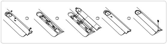
Installing batteries (Battery size: AAA)
NOTE
•• Usethe remote controlwithin 7m ofthe TV.
•• Bright light mayaffectthe performance ofthe remote control.Avoid using nearbyspecialfluorescent light or neon signs.
•• The colour and shape may vary depending on the model.
•• Remote control button 'HOME'& '3D'are not supported.When pressingthese buttons,the TVunitdoes not respond.
English 17
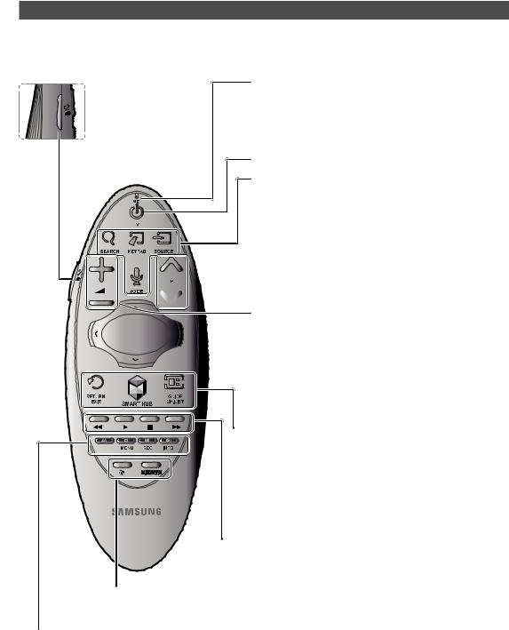
Samsung Smart Control (sold separately)
This function is supported for the HG32EE690 series models or higher in specific geographical areas.
Colours and shape may vary depending on the model.
¢: Turns the sound on/off. |
MIC: Usethe microphonewiththeVoice Control andVoicefunctions. |
‒‒ The Voice Control function can be affected by unclear pronuncia |
|
AD: Press and holdthis button |
tion, voice level, or surrounding noise. |
to bring upthe Accessibility |
|
Shortcuts panel. Select the |
|
options to turn them on or off. |
|
|
Turns the TV on/off. |
|
SEARCH: Pressthis buttonto usethe searchwindow. (Not available) |
|
KEYPAD: With the virtual remote control on the screen, you can easily |
|
enter digits, control content, and use functions. |
|
SOURCE: Changesthe source. |
|
VOICE: Starts voice recognition. When the microphone icon appears on |
|
the screen, sayavoice command intothe microphone. Say"Help"to |
|
learn about basic usageandvoice commands. |
|
‒‒ Sayavoice command10cmto15cmfromthe microphone and at an |
|
appropriate volume. |

 Changesthe channel.
Changesthevolume.
 ‒‒ Touchpad: Place a fingeron the touch pad and move the Samsung Smart Control. The pointer on the screen moves in the direction and as much as the Samsung Smart Control is moved. Press the
touchpad to run the focused item.
‒‒ <>¡£: Moves the pointer or focus.
 RETURN: Returnstothe previous menu.Additionally,whenyou press this buttonwhilewatching TV,you can returntothe previous channel.
EXIT: Press and holdthis buttonto exit allcurrentlyrunning applications.
SMART HUB: Launches Smart Hub. Pressing SMART HUB while an application is running terminates the application.
GUIDE: Displaysthe digitalchannel broadcasting schedule.
CH.LIST: Press and hold to launch the Channel List.
 Usethese buttonswith specificfeatures. Usethese buttons according
to the directions on the TV screen.
¥: Enable Football Mode foran optimal sportsviewing experience.
M.SCREEN: You can splitthe TVscreen and usevariousfunctions such aswatching TV, surfingtheweb,watching video, and so on. For more information, refer to the e-Manual.
Colours button: Usethese colourbuttonsto access additional options specifictothefeature inuse. ‒‒ MENU: Press and hold to display a menu on the screen.
‒‒ REC: Press and holdto recordthe broadcast.
‒‒ INFO: Press and holdtoviewinformation aboutthe current digital channel ormediafile.
18 English
Inserting Batteries into Samsung Smart Control
To use Samsung Smart Control,first refertothefigure belowand insertbatteriesintothe unit.
Gentlypullonthe batterycover's notch andthen removethe covercompletelyonce it comes loose.
Insert 2AAalkaline batteries, making sureto alignthe positive andnegative polarities correctly.
¦¦Using the Samsung Smart Control
Samsung Smart Controlmakes it even easierand more convenientto usethe TV. Pressingthe KEYPAD button displays a
virtual remote control that allows you to easily enter digits, control content, and activate functions on the screen.
‒‒ We recommend using Samsung Smart Control at a distance of less than 6m.Ausable distance maydifferdepending on the wireless environmental conditions.
Pairing the Samsung Smart Control
To controlthe TVwith Samsung SmartControl,you needto pairSamsung Smart Controltothe TVviaBluetooth. Pair
Samsung Smart Controltothe TV.
‒‒ Samsung Smart Control can onlybe pairedto a single TV.
Point Samsung Smart Control atthe remote control sensorofthe TVand pressthe TV buttontoturnthe TVon.
‒‒ Remote control receiver’s location mayvarydepending onthe model.
Reconnecting Samsung Smart Control
Ifthe Samsung Smart Control stopsoperating orworks abnormally, replacethebatteries asthis maybe dueto insufficient batterypower.
Ifthe problem persists,the Samsung Smart Control restores pairingwiththe TV.
1. Press RETURN button and GUIDE button simultaneouslyfor3 seconds.
‒‒ You must place the Samsung Smart Control approximately 30cm ~ 40cm away from the TV and ensure it is pointing towards the remote control receiver.
2. Connection image is appeared onthe screen.Andthen, Samsung Smart Controlis connectingto TVautomatically.
English 19
When you see this alarm icon on the screen...
Following alarm iconindicates Samsung Smart Control's batteries are low. Ifthe alarm icon pops up, replacethe batteries. Samsung recommends using alkaline batteriesfora longer operating life.
<LowbatteryAlarm Icon>
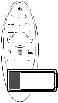
Using the TV by Moving the Samsung Smart Control
The Samsung Smart Controlhas a motion sensor(gyro sensor)that allowsyouto easilycontrolthe TVbyholding and movingthe Samsung Smart Control.
Afterplacing afingeronthetouchpad, a pointerappears onthe screen. Hold and movethe Samsung Smart Control. The pointermovesthe samewaythe Samsung Smart Control is moved. It's also possibleto scroll up and downon scrollable
screens.
‒‒ Ifyou removethefingerfromtouchpad,the screen pointerdisappears.
Using the TV with the Touchpad
Navigate to the Support menu and select the Smart Control Tutorial option to learn how to use the touchpad, following the on screen instructions.
Moving the Focus/Pointer
Pressthe directional buttons (up, down, left, and right)to movethe pointerorfocus inthe direction.
Menu Access & Item Selection
Press the touchpad. This lets you access a TV menu or select an item.
Displaying the Context-sensitive Menu on Smart Hub
Press andholdonthetouchpadfromtheSmart Hubscreen. The Optionsmenu availabletothe selecteditem appears.
‒‒ The Options menu depends onthe context.
Moving to the Smart Hub panel
Onthe Smart Hub screen, drag left orright onthetouchpad. Thiswill movethe Smart Hub panels left orright.
Scrolling on the Web Browser
Drag up/down onthetouchpad inthewebbrowserscreen. This scrollsthroughtheweb screen.
20 English
Connecting the TV with SBB
TVRearPanel
ETH MODEM
DataCable
The rear panel may differ depending on the model.
1.Connectthe DATA jack ofthe TVtothe [ETH MODEM] jack ofthe STB (SBB)withthe Data cable.
Use data communication.
¦¦List of Vendors and Compatible Data Cables Supplied with the TV
••Confirmthatyou are usingthe correct data cableforyourvendor. Refertothe code label onthe datacables.
6 |
|
|
1 |
|
1 |
|
|
6 |
|
CON A |
|
|
CON B |
|
CON A |
CON A |
CON B |
CON B |
|
6: NC |
5 |
6 |
1: NC |
|
5: IR |
2: GND |
|||
4 |
2 |
|||
4: GND |
3: Rx |
|||
3: Rx |
3 |
5 |
4: NC |
|
2: Tx |
5: Tx |
|||
2 |
3 |
|||
1: Nc |
6: IR |
Operation Specification of Data Cable(RJ12) : RS232
English 21

Connecting the Bathroom Speakers
You can connectthe Bathroom Speakers usingthefollowing method.
¦¦ConnectingthroughtheVariableOutput(availablewithoutanexternalamplifier)
TVRearPanel
1
Speaker
2 |
VOL+ |
Volume Control Box |
|
VOL- |
|
The rear panel may differ depending on the model.
1.Connectthe VARIABLE AUDIO OUT port ofthe TVtothe BathroomWall Speakers ofthehotel.
Speaker+
Speaker - |
N/C |
|
2.Connectthe VOL-CTRL jack ofthe TVtotheVolume Control Box Switch port onthe BathroomWall ofthe hotel.The maximum speaker output is 4W, 8Ω.
The VARIABLE AUDIO OUT port supports MONO sound out only.
•• InstallingtheVolume Control
‒‒ If you configure the Volume Control Box as shown in the figure, you can control the volume of the bathroom speakers.
‒‒ The jackthat connectstheVolume Control Boxtothe TVis a 3.5mm normal Phone jack. ‒‒ Volume Control Box switch is a Tact switch.
Setting the Sub AMP Mode
‒‒ 0: Turnsthe SubAMPfunction off (PWM off).
‒‒ 1: Determines the Subvolume according to the mainvolume control. The subvolume is determined according to the PowerOnVolume,the MinVolume, andthe MaxVolumevalues of Hotel Mode.
‒‒ 2: Determinesthevolume accordingtothe bathroom control panel setting.
•• Variable Output Port Specifications
‒‒ Speaker Wire: Use speakercable no morethan 82feet (25m) in length.
VOLUP(Black /Red2) |
|
Volume Control Box |
|
|
|
1 |
VOL + |
|
|
|
|
|
|
|
3 |
|
|
2 |
VOL - |
|
|
|
|
VOLDOWN |
GND (Shield |
|
|
(White 1) |
Wire 3) |
|
|
22 English
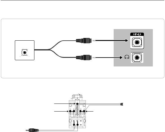
¦¦Audio Loop In
An additional Headphone Box can be installedon abed orbusinessdeskforadded convenience. The installation procedures are given below.
•• Detailed Drawing ofthe Headphone Box.
HEADPHON BOX
Headphone Box
The rear panel may differ depending on the model.
Shield wire
Red Wire (Audio-R)
Red wire + White wire 


TV HP-ID jack
<Headphone Box>
TVRearPanel


 TV Headphones jack
Whitewire (Audio-L)
Shield Wire
English 23
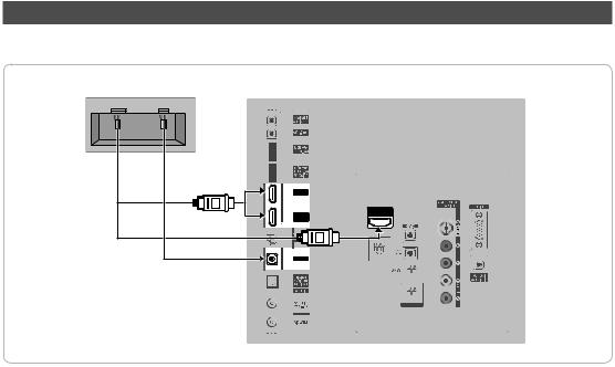
Connecting the MediaHub HD
Outputto anyexternal source connectedto MediaHub HD onthe hotel desk.
MediaHub HD Rear |
TVRearPanel |
||
HDMI USB RS/232 |
|
||
|
|
|
|
2HDMI cable |
1RS-232 Data Cable
HDMI IN 3 (ARC)
The rear panel may differ depending on the model.
1.Connectthe RJP port ofthe TVandthe RS/232 port ofthe MediaHub HD.
2.ConnecttheHDMI IN 1, 2 or 3 port ofthe TVandthe HDMIportofthe MediaHub HD.
••MediaHubHD
‒‒ The MediaHub HD is a hardware module that has different Audio Video inputs (A/V, Audio, PC, HDMI and USB) and corresponding outputs. The corresponding output sources connect from MediaHub to the TV. MediaHub communicates with the TV via RS232. Hot Plug & Play is a function that allows hotel guests to connect an external source to the MediaHub. MediaHub communicates with the TV by sending messages regarding Active/ Inactive sources. The TVswitchestotheActive external source.
‒‒ You haveto connectthe HDMI ofthe MediaHubtothe HDMI IN 3 port of the TV. ‒‒ Whenthe TVis on, connectthe TVandthe RJPwithin10 seconds.
•• Special features ‒‒ PIP
‒‒ Auto Detection
24 English
 Loading...