


 Loading...
Samsung HG32AE570, HG32EE470, HG48AE570, HG58AE570, HG24EE460 User Manual
...460/470/570/670
LED TV
Installation manual
Thank you for purchasing this Samsung product. To ensure full warranty coverage, please register your product at
www.samsung.com/register
Model |
Serial No. |

Figures and illustrations in this User Manual are provided for reference only and may differ in appearance from the actual product. Product design and specifications may be changed without notice.
Instruction
This TV offers an interactive functionality through a set-back box (SBB/STB) that is connected to the TV, and can be connected with other TVs in a computer controlled system for hotels and other hospitality businesses.
yy Interactive:WhentheTVispowered-upinitially,itsendsacommandtoidentifytheSBB/STB.Onceidentified,theTVswitchesto
ONLINE mode, and is fully controlled through the SBB/STB. When the TV is in ONLINE mode, it ignores IR (Samsung remote) commands and acts according to the interface protocol.
yy Stand-Alone:IfSBB/STBisnotidentified,theTVshouldbeswitchedtoSTAND-ALONEmodewithrestrictedoperations.
Operational Modes
When this TV (in Hotel mode) is operated with a SBB/STB, it is in one of two states:
yy ONLINEorSTAND-ALONE.InSTAND-ALONEstate,theTVwillactasaHotelTV,butwithoutactivecommunication.Thispreventsguests from trying to cheat the system by disconnecting the SBB/STB.
|
Hotel TV |
Stand-alone |
|
|
SBB/STB Online if |
Mode |
|
Hotel Mode On |
|
||
|
|
||
|
|
successful within |
|
|
|
10 attempts |
|
Power |
|
SBB/STB |
SBB/STB Status- |
|
Online-10 |
Attemptevery |
|
ON |
|
||
|
consecutive fails |
2secs |
|
Online Mode
Poll Rate 20/sec
To set the details regarding Stand-alone or interactive mode, refer to pages 41-46 (Setting the hotel option data: Stand-alone mode and Interactive mode)
yy Some operations may be restricted to prevent guests from “cheating” the TV system.
yy Nomainmenu(Interactivemode)orChannelMenu,Plug&PlayinMainMenu(Stand-Alonemode) yy Limited Volume and Panel key lock or unlock
Still image warning
Avoid displaying still images (like jpeg picturefiles) orstill image elements (watermark images such as TVProgram/Network logos,the panorama or4:3 imageformat, stock ornews bars atthe bottom ofthe screen etc.)onthe screen. Constantlydisplaying still pictures can cause uneven wear of the screen phosphor, which will affect the image quality. To reduce risk of this effect, please follow the recommendations below:
yy AvoiddisplayingthesameTVchannelforlongperiodsoftime.
yy Alwaystrytodisplayanyimageoverthefullscreen,usingtheTVsetpictureformatmenuforthebestpossiblematch.
yy Reduce the brightness and contrast values to the minimum required to achieve the desired picture quality. Exceeding these values may accelerate the burnout process.
yy Frequently use TV features designed to reduce image retention and screen burnout; please refer to the appropriate user manual section for more details.
Securing the Installation Space
Maintainthe required distance betweenthe product and otherobjects (e.g.walls)to ensure properventilation.
Failure to do so may result in fire or a problem with the product due to an increase in its internal temperature.When using a stand or wall-mount, use parts provided by Samsung Electronics only.
yy Useofpartsprovidedbyothermanufacturersmayresultinaproblemwiththeproduct,orinaninjuryduetotheproductfalling.
The appearance may differ depending on the product.
Installation with a stand |
Installation with a wall mount |
10 cm
10 cm |
10 cm 10 cm |
 10 cm
10 cm
10 cm
 10 cm
10 cm

Contents
yy |
Accessories.................................................................................................................................................................... |
4 |
yy Installing the LED TV Stand........................................................................................................................................ |
4 |
|
yy |
Assemblingthe swivel................................................................................................................................................. |
15 |
yy Overview of the Connection Panel............................................................................................................................ |
17 |
|
yy Using the TV’s Controller............................................................................................................................................. |
29 |
|
yy Viewing the Remote Control...................................................................................................................................... |
30 |
|
yy Connecting the TV with the SBB................................................................................................................................ |
34 |
|
yy Connecting the Bathroom Speakers......................................................................................................................... |
36 |
|
yy Connecting the MediaHub HD.................................................................................................................................... |
38 |
|
yy Connecting the RJP (Remote Jack Pack).................................................................................................................. |
39 |
|
yy Setting the Hotel Option Data.................................................................................................................................... |
41 |
|
yy |
Installing the Wall Mount............................................................................................................................................ |
68 |
yy Securing the TV to the Wall......................................................................................................................................... |
70 |
|
yy |
Anti-theft Kensington Lock........................................................................................................................................ |
70 |
yy |
Specifications................................................................................................................................................................ |
71 |
ENGLISH
English 3
Accessories
Please make sure the following items are included with your LED TV. If any items are missing, contact your dealer.The colors and shapes of the following items may vary depending on the model.
yy Remote Control & Batteries (AAAx 2) |
yy |
Quick Setup Guide |
yy Power Cord |
yy |
Guide Stand |
yy Safety Guide (Not included with all models) |
yy |
Screws |
yy Hotel Mount Kit (Not includedwith all models) |
yy |
Stand |
yy Data Cable (Not included with all models) |
yy Holder-Stand Cable (Not included with all models) |
|
yy Wall MountAdapter(Not includedwith all models) |
|
|
The stand and stand screws may not be included depending on the model.The Data Cable may not be included depending on the SI Vendor.
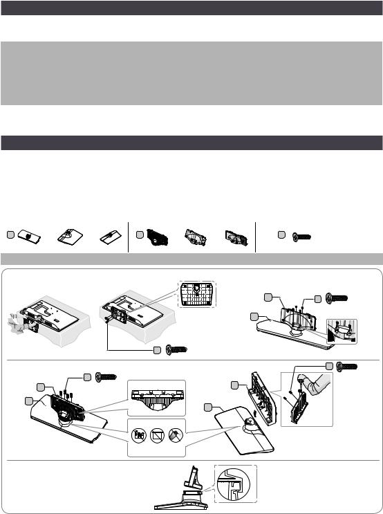
Installing the LED TV Stand
Stand Components
When installing the stand, use the components and parts provided.
HG**EE470
A |
or |
or |
B |
|
or |
or |
C |
(M4 X L12) |
|
Stand |
|
|
|
Guide Stand |
|
Screws |
|
1 |
|
|
|
|
|
|
|
|
|
HG24EE470 |
|
|
|
|
|
HG40EE470/HG48EE470 |
|
|
|
|
|
|
|
|
B |
C |
|
|
|
|
|
|
|
A |
x4 (M4 X L12) |
|
|
|
|
|
|
|
|
|
|
|
|
|
C |
|
x3 (M4 X L12) |
|
|
|
HG32EE470 |
|
|
|
|
HG28EE470 |
|
C |
|
|
C |
Top View |
|
B |
|
x4 (M4 X L12) |
|
|
B |
x4 (M4 X L12) |
|
|
|
|||
|
A |
Front |
|
|
|
A |
|
|
|
|
|
|
|
|
|
|
|
|
|
|
ATTENTION |
|
|
Top View |
||
|
|
|
|
|
|
|||
|
Rear |
|
|
|
|
|
|
|
|
|
|
DO NOT USE |
DO NOT USE |
DO NOT |
|
|
|
|
|
|
CHEMICALS |
GREASE |
USE OIL |
|
|
|
Side
4 English

2 |
3 |
HG32EE470/HG40EE470/HG48EE470 HG28EE470
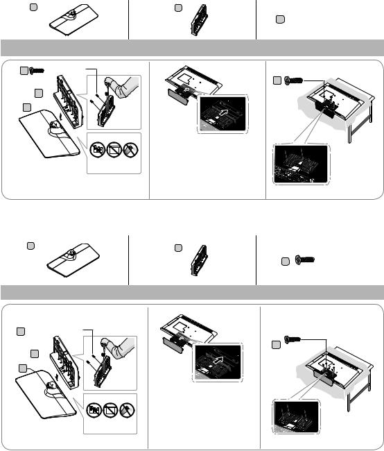
Place a soft cloth on a table to protect the TV, and then lay the TV flat on the cloth, screen side down.
Insert the Stand Guide into the slot on the bottom of the TV.
4
HG32EE470 |
HG40EE470/HG48EE470 |
|
HG28EE470 |
|
x4 (M4 X L12) |
x4 (M4 X L12) |
x3 (M4 X L12) |
|
|
||
|
|
|
HG24EE460
A |
B |
x3 (M4 X L12) |
|
||
Stand |
|
Screws |
1 |
2 |
|
English 5
HG28EE460
A |
B |
C 


 x7 (M4 X L12)
Stand |
Guide Stand |
Screws |
1 C |
x4 (M4 X L12) |
2 |
Front |
|
|
B 


A 
3
C
x3 (M4 X L12) |
TOP View
ATTENTION
DO NOT USE |
DO NOT USE |
DO NOT |
CHEMICALS |
GREASE |
USE OIL |
Place a soft cloth on the table to protect the TV, and then lay the TV flat on the cloth, screen-side down.
Insert the Stand Guide into the slot on the bottom of the TV.
HG32EE460/HG32AE460
A
Stand
1
C 


 x4 (M4 X L12)
Front
B 


A
TOP
View
ATTENTION
DO NOT USE |
DO NOT USE |
DO NOT |
CHEMICALS |
GREASE |
USE OIL |
B |
|
|
|
C |
x8 (M4 X L12) |
Guide Stand |
|
Screws |
2 |
3 |
|
|
C x4 (M4 X L12) |
|
Place a soft cloth on the table to protect the TV, and then lay the TV flat on the cloth, screen-side down.
Insert the Stand Guide into the slot on the bottom of the TV.
6 English

HG40EE460/HG40AE460/HG48AE460/HG43AE570/HG48AE570
A |
L |
R |
|
B |
|
L:1EA |
|
|
|
2EA |
|
R:1EA |
|
|
|
|
|
|
Stand |
Guide Stand |
1 |
|
2 |
4 |
5 |
|
C |
x4 (M4 X L12) |
|
Screws
3
C 


 x4 (M4 X L12)
6
! |
HG32AE570
A |
B |
|
|
C |
(M4 X L12) |
Stand |
Guide Stand |
Screws |
1 |
|
|
|
C |
x4 (M4 X L12) |
English 7
2
!
3
C |
x3 (M4 X L12) |
!
8 English

HG32AE570
A |
B |
x4 (M4 X L12) |
|
||
|
|
Stand |
Screws |
1 |
2 |
x2 (M4 X L12) |
x2 (M4 X L12) |
|
3
English 9

HG43AE570/HG48AE570
A |
|
B |
|
C |
x4 (M4 X L12) |
Stand |
Guide Stand |
Screws |
1 |
|
|
2 |
3 |
x4 (M4 X L12)
10 English
HG58AE570
A |
B |
|
Stand |
Guide Stand |
1 |
|
|
C |
|
x4 (M4 X L12) |
|
B |
|
|
|
A |
2 |
3 |
4


 x4 (M4 X L12)
C |
x8 (M4 X L12) |
Screws


 x4 (M4 X L12)
English 11

HG49AE570
A |
B |
C |
4EA: M4 XL12 ( ) |
|
|
C |
4EA: M4 X L12 ( ) |
Stand |
|
Guide Stand |
Screws |
1
2
C 


 4EA: M4 X L12 ( )
B
A
3
4
C 


 4EA: M4 X L12 ( )
12 English
HG**AE570 (Excluding China and Hongkong)
A |
|
B |
C |
|
|
|
(M4 X L12) |
||
|
|
or |
||
Stand |
|
Guide Stand |
|
Screws |
1-1 |
C |
x4 (M4 X L12) |
1-2 |
|
|
|
|||
B |
|
|
|
|
A |
|
|
|
|
|
|
Attention |
|
|
DO NOT USE |
DO NOT USE |
DO NOT |
CHEMICALS |
GREASE |
USE OIL |
1-3 |
C |
X4 (M4 X L12)
Tighten the bottom of the screw first, and stow the upper side of screw last.
Proceed with connecting the screw, following the instructions in the manual.
Place a soft cloth on the table to protect the TV, and then lay the TV flat on the cloth, screen-side down.
Insert the Stand Guide into the slot on the bottom of the TV.
Slide and assemble it to the end line in the direction of the arrow.
2 HG40AE570/HG48AE570/HG43AE570 |
3 |
Place a soft cloth on the table to protect the TV, and then lay the TV flat on the cloth, screen-side down.
Insert the Stand Guide into the slot on the bottom of the TV.
4 HG40AE570/HG48AE570/HG43AE570
x4 (M4 X L12)
English 13

HG**EE670
|
A 1 EA |
B 1 EA |
C |
32" x7 (M4 X L12) |
|
|
|
||
|
|
|
|
40"~55" x8 (M4 X L12) |
|
32"~55" |
32" |
40"~55" |
|
|
|
|
|
|
|
Stand |
Guide Stand |
Screws |
|
1 |
C |
x4 |
1-1 |
|
|
|
|||
|
|
(M4 X L12) |
|
|
|
B |
|
1-2 |
|
|
|
|
|
|
A
2 |
Place a soft cloth on the table to protect the TV, and |
|
then lay the TV flat on the cloth, screen-side down. |
||
|
2-1 |
2-2 |
2-3 |
3 3-1 |
3-2 |
3-1 |
3-2 |
C 32" |
C 40" ~ 55" |
x3 (M4 X L12) |
x4 (M4 X L12) |
14 English

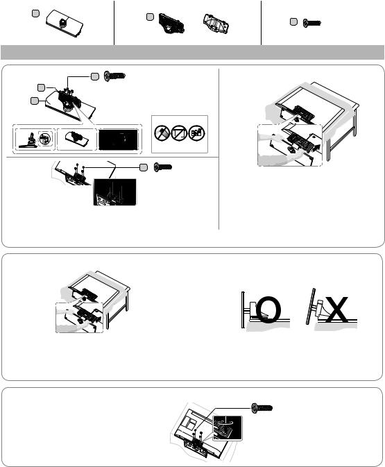
Assembling the swivel
Some models support the swivel function. Supported swivel angles are 20°, 60° and 90°, and you can change the swivel angle using BRACKETHOLDER SWIVEL.
Support the swivel models : HG**EE670
HG32EE470
HG40EE470
HG48EE470
HG32AE570SW/K
HG40AE570SW/K
HG43AE570SW/K
HG48AE570SW/K
20° ~ 60° swivel
Ifyou assemblethewedge onthe bottomofthe standtothe hole of BRACKETHOLDER SWIVELwhere 20° or60° is marked,the swivel angle becomes 20°~ 60° inthe left and right side.
(The shape of the stand depends on the model.)
90° swivel
Ifyou assemble onlyscrews afteryou remove BRACKETHOLDER SWIVEL,the swivel angle becomes each 90°inthe left and right side.
English 15

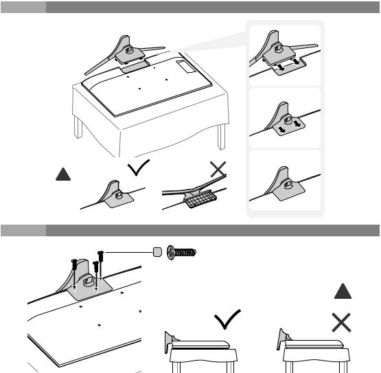
Hotel Mount Kit (Not included with all models)
Bolt + Nut
Short Bolt (2EA) |
Long Bolt(2EA) |
Nut (2EA) |
Washer(2EA) |
|
Top |
|
|
|
|
Affixthe standto aflat surface such as a dressertop,desk |
|
|
Bottom |
top, or entertainment center, as shown in the figure. |
|
WARNING: To prevent injury,this apparatus must be securelyattachedtothefloor/table inaccordance with the installation instructions.
16 English
Overview of the Connection Panel
5 @
|
|
PC / DVI |
RJP |
HDMI IN |
AUDIO IN |
|
(ARC) |
|
|
|
AV IN |
|
|
VIDEO |
%
ANT IN
DATA |
HP-ID |
$ 1 3 4
|
2 1 |
7 |
|
DATA |
|
|
|
PC / DVI |
3 |
|
AUDIO IN |
CLOCK |
|
|
|
AV |
|
|
|
|
4 |
|
|
|
HP-ID |
|
5 |
|
PC IN |
|
RJP |
|
|
|
%8
HG24EE470
#(5V 0.5A)/ CLONING
!COMMON INTERFACE
HG28EE470
!COMMON INTERFACE
@HDMI IN (DVI/ARC)
#(5V 0.5A)/ CLONING
$ |
ANT IN |
|
English 17

% 5 7
RJP
PC / DVI
AUDIO IN
PC IN |
8 |
|
HDMI IN |
|
(DVI/ARC) |
|
@ |
DATA |
|
|
HP-ID |
1 |
4 3 |
1 |
7 |
DATA |
|
|
PC / DVI |
|
AUDIO IN |
AV IN |
|
3 |
VIDEO |
|
4

HP-ID
PC IN
RJP
5 % 8
HG32EE470
#(5V 0.5A)/ CLONING
!COMMON INTERFACE
$ |
ANT IN |
|
HG40EE470
HG48EE470
!COMMON INTERFACE
@HDMI IN (DVI/ARC)
#(5V 0.5A) /CLONING
$ |
ANT IN |
18 English
5@ $ 6
RJP
HDMI IN (ARC)
#USB
(5V 0.5A)
/CLONING
 AUDIO
AUDIO
! |
COMMON |
|
INTERFACE |
|
HP-ID |
|
ANT IN |
|
|
4 3 |
6 |
! |
COMMON |
|
PC/DVI |
|
INTERFACE |
|
AUDIO IN |
|
|
|
|
@ |
HDMI IN |
|
|
|
(DVI/ARC) |
|
|
|
|
HP-ID |
PC IN |
# |
(5V 0.5A) |
|
AUDIO |
USB |
|
|
|
/ CLONING |
RJP |
|
|
$ |
ANT IN |
|
|
|
|
|
HG24EE460
4
3
HG28EE460
7
8
5
English 19

|
LO |
65 |
|
(5V |
RJP |
|
.0 |
|
# |
USB |
|
5A)/C |
|
|
NING |
PC/DVI |
|
|
AUDIO IN |
|
|
|
|
! |
COMMON INTERFACE |
AUDIO |
|
|
PC IN |
|
|
HDMI IN |
|
|
(DVI/ARC) |
$ |
|
HP-ID |
IN ANT |
|
4 3 6
PC/DVI ! COMMON AUDIO IN
INTERFACE
@ |
HDMI IN |
|
|
(DVI/ARC) |
HP-ID |
PC IN |
|
|
|||
# |
USB |
|
AUDIO |
(5V 0.5A) |
|
RJP |
|
/ CLONING |
|
|
|
$ |
ANT IN |
|
|
|
|
|
HG32EE460
7
8
@
3
4
HG40EE460
7
8
5
20 English
|
4 |
6 8 |
|
|
|
|
|
PC IN |
|
|
HP-ID |
|
|
|
3 |
|
|
PC/DVI |
7 |
|
|
AUDIO IN |
||
1 |
DATA |
AUDIO |
VARIABLE |
9 |
|
|
|||
|
|
|
AUDIO OUT |
|
2 |
CLOCK |
|
VOL-CTRL |
0 |
RJP
5
5
RJP
#
PC / DVI
AUDIO IN
AV IN |
|
|
7 |
|
VIDEO |
|
|
6 |
AUDIO |
PC IN |
8 |
|
|||
|
|
|
HDMI IN (DVI/ARC)
@
HP-ID
$
4 3
HG32EE670
HG40EE670
HG49EE670
HG55EE670
HG32AE460
 5A)/CLONIN.0 (5VG
IN ANT
English 21

|
(5V |
# |
5A)/CLONING.0 |
|
$ |
ANT |
@HDMI
(DVI/ARC)
#(5V 0.5A) / CLONING
$ |
ANT |
|
5
RJP


右
PC/DVI
PC
HDMI
(DVI/ARC)
HP-ID
6 4 3
3 4 6
B
AV IN

HP-ID |
|
|
|
|
|
|
|
|
|
RJP |
|
|
|
|
|
|
|
5
HG32AE460
(TAIWAN)
7
8
@
HG40AE460
(TAIWAN)
PC/DVI |
7 |
|
8
PC
22 English
Loading...