


PROJECTION TV RECEIVER
Chassis : P55A(N) REV.1
Model : HCN4226WX/XAA
HCN4226W3S/XAA
ST54T8PCS/XAX
HCN4727W5S/XAA
PROJECTION TV RECEIVER |
|
CONTENTS |
1. Precautions
2. Reference Information
3. Specifications
4. Alignment and Adjustments
5. Troubleshooting
6. Exploded View and Parts List
7. Electric Parts List
8. Block Diagrams
9. Wiring Diagram
10. Schematic Diagrams

Precautions
1. Precautions
Follow these safety, servicing and ESD precautions to prevent damage and protect against potential hazards such as electrical shock and X-rays.
1-1 Safety Precautions
1.Be sure that all of the built-in protective devices are replaced. Restore any missing protective shields.
2.When reinstalling the chassis and its assemblies, be sure to restore all protective devices, including: nonmetallic control knobs and compartment covers.
3.Make sure that there are no cabinet openings through which people—particularly children—might insert fingers and contact dangerous voltages. Such openings include the spacing between the picture tube and the cabinet mask, excessively wide cabinet ventilation slots, and improperly fitted back covers.
If the measured resistance is less than 1.0 megohm or greater than 5.2 megohms, an abnormality exists that must be corrected before the unit is returned to the customer.
4.Leakage Current Hot Check (Figure 1-1): Warning: Do not use an isolation transformer during this test. Use a leakagecurrent tester or a metering system that complies with American National Standards Institute (ANIS C101.1, Leakage Current for Appliances), and Underwriters Laboratories (UL Publication UL1410, 59.7).
5.With the unit completely reassembled, plug the AC line cord directly into the power outlet. With the unit’s AC switch first in the ON position and then OFF, measure the current between a known earth ground (metal water pipe, conduit, etc.) and all exposed metal parts, including: antennas, handle brackets, metal cabinets, screwheads and control shafts. The current measured should not exceed 0.5 milliamp. Reverse the powerplug prongs in the AC outlet and repeat the test.
|
|
|
|
|
|
|
|
(READING SHOULD |
||
|
|
|
|
|
|
|
|
|||
|
|
|
|
|
LEAKAGE |
NOT BE ABOVE |
||||
DEVICE |
|
|
|
|
CURRENT |
|
0.5mA) |
|||
UNDER |
|
|
|
|
TESTER |
|
|
|
||
TEST |
|
|
|
|
|
|
|
|
|
|
|
|
|
|
|
|
|||||
|
|
TEST ALL |
|
|
|
|
|
|
||
|
EXPOSED METAL |
|
|
|
|
|
|
|||
|
|
SURFACES |
|
|
|
|
|
|
||
2-WIRE CORD |
|
|
|
|
|
|
||||
ALSO TEST WITH |
|
|
|
|
|
|
||||
PLUG REVERSED |
|
|
|
|
|
|
|
|||
(USING AC ADAPTER |
|
|
|
|
|
|
EARTH |
|||
PLUG AS REQUIRED) |
|
|
|
|
GROUND |
|||||
Fig. 1-1 AC Leakage Test
6.Antenna Cold Check:
With the unit’s AC plug disconnected from the AC source, connect an electrical jumper across the two AC prongs. Connect one lead of the ohmmeter to an AC prong. Connect the other lead to the coaxial connector.
7.X-ray Limits:
The picture tube is especially designed to prohibit X-ray emissions. To ensure continued X-ray protection, replace the picture tube only with one that is the same type as the original. Carefully reinstall the picture tube shields and mounting hardware; these also provide X-ray protection.
8.High Voltage Limits:
High voltage must be measured each time servicing is done on the B+, horizontal deflection or high voltage circuits. Correct operation of the X-ray protection circuits must be reconfirmed whenever they are serviced. (X-ray protection circuits also may be called “horizontal disable” or “hold-down”.)
Heed the high voltage limits. These include the X–ray Protection Specifications Label, and the Product Safety and X-ray Warning Note on the service data schematic.
Samsung Electronics |
1-1 |

Precautions
1-1 Safety Precautions (Continued)
9.High voltage is maintained within specified limits by close-tolerance, safety-related components and adjustments. If the high voltage exceeds the specified limits, check each of the special components.
10.Design Alteration Warning:
Never alter or add to the mechanical or electrical design of this unit. Example: Do not add auxiliary audio or video connectors. Such alterations might create a safety hazard. Also, any design changes or additions will void the manufacturer’s warranty.
11.Hot Chassis Warning:
Some TV receiver chassis are electrically connected directly to one conductor of the AC power cord. If an isolation transformer is not used, these units may be safely serviced only if the AC power plug is inserted so that the chassis is connected to the ground side of the AC source.
To confirm that the AC power plug is inserted correctly, do the following: Using an AC voltmeter, measure the voltage between the chassis and a known earth ground. If the reading is greater than 1.0V, remove the AC power plug, reverse its polarity and reinsert. Re-measure the voltage between the chassis and ground.
12.Some TV chassis are designed to operate with 85 volts AC between chassis and ground, regardless of the AC plug polarity. These units can be safely serviced only if an isolation transformer inserted between the receiver and the power source.
13.Some TV chassis have a secondary ground system in addition to the main chassis ground. This secondary ground system is not
isolated from the AC power line. The two ground systems are electrically separated by insulating material that must not be defeated or altered.
14.Components, parts and wiring that appear to have overheated or that are otherwise damaged should be replaced with parts that meet the original specifications. Always determine the cause of damage or overheating, and correct any potential hazards.
15.Observe the original lead dress, especially near the following areas: Antenna wiring, sharp edges, and especially the AC and high voltage power supplies. Always inspect for pinched, out-of-place, or frayed wiring. Do not change the spacing between components and the printed circuit board. Check the AC power cord for damage. Make sure that leads and components do not touch thermally hot parts.
16.Picture Tube Implosion Warning:
The picture tube in this receiver employs “integral implosion” protection. To ensure continued implosion protection, make sure that the replacement picture tube is the same as the original.
17.Do not remove, install or handle the picture tube without first putting on shatterproof goggles equipped with side shields. Never handle the picture tube by its neck. Some “in-line” picture tubes are equipped with a permanently attached deflection yoke; do not try to remove such “permanently attached” yokes from the picture tube.
18.Product Safety Notice:
Some electrical and mechanical parts have special safety-related characteristics which might not be obvious from visual inspection. These safety features and the protection they give might be lost if the replacement component differs from the original—even if the replacement is rated for higher voltage, wattage, etc.
Components that are critical for safety are indicated in the circuit diagram by shading,
(  ) or (
 ).
).
Use replacement components that have the same ratings, especially for flame resistance and dielectric strength specifications.
A replacement part that does not have the same safety characteristics as the original might create shock, fire or other hazards.
1-2 |
Samsung Electronics |
Precautions
1-2 Servicing Precautions
Warning 1 : First read the “Safety Precautions” section of this manual. If some unforeseen circumstance creates a conflict between the servicing and safety precautions, always follow the safety precautions.
Warning 2 : An electrolytic capacitor installed with the wrong polarity might explode.
1.Servicing precautions are printed on the cabinet. Follow them.
2.Always unplug the unit’s AC power cord from the AC power source before attempting to: (a) Remove or reinstall any component or assembly, (b) Disconnect an electrical plug or connector, (c) Connect a test component in parallel with an electrolytic capacitor.
3.Some components are raised above the printed circuit board for safety. An insulation tube or tape is sometimes used. The internal wiring is sometimes clamped to prevent contact with thermally hot components. Reinstall all such elements to their original position.
4.After servicing, always check that the screws, components and wiring have been correctly reinstalled. Make sure that the portion around the serviced part has not been damaged.
5.Check the insulation between the blades of the AC plug and accessible conductive parts (examples: metal panels, input terminals and earphone jacks).
6.Insulation Checking Procedure: Disconnect the power cord from the AC source and turn the power switch ON. Connect an insulation resistance meter (500V) to the blades of the AC plug.
The insulation resistance between each blade of the AC plug and accessible conductive parts (see above) should be greater than 1 megohm.
7.Never defeat any of the B+ voltage interlocks. Do not apply AC power to the unit (or any of its assemblies) unless all solid-state heat sinks are correctly installed.
8.Always connect a test instrument’s ground lead to the instrument chassis ground before connecting the positive lead; always remove the instrument’s ground lead last.
9.When some parts inside the optical engine (except lamp) are damaged, replace the whole optical engine.
“CAUTION : Double-pole/neutral fusing”
Samsung Electronics |
1-3 |

Precautions
1-3 Precautions for Electrostatically Sensitive Devices (ESDs)
1.Some semiconductor (“solid state”) devices are easily damaged by static electricity. Such components are called Electrostatically Sensitive Devices (ESDs); examples include integrated circuits and some field-effect transistors. The following techniques will reduce the occurrence of component damage caused by static electricity.
2.Immediately before handling any semicon ductor components or assemblies, drain the electrostatic charge from your body by touching a known earth ground. Alternatively, wear a discharging wrist-strap device. (Be sure to remove it prior to applying power— this is an electric shock precaution.)
3.After removing an ESD-equipped assembly, place it on a conductive surface such as aluminum foil to prevent accumulation of electrostatic charge.
4.Do not use freon-propelled chemicals. These can generate electrical charges that damage ESDs.
5.Use only a grounded-tip soldering iron when soldering or unsoldering ESDs.
6.Use only an anti-static solder removal device. Many solder removal devices are not rated as “anti-static”; these can accumulate sufficient electrical charge to damage ESDs.
7.Do not remove a replacement ESD from its protective package until you are ready to install it. Most replacement ESDs are packaged with leads that are electrically shorted together by conductive foam, aluminum foil or other conductive materials.
8.Immediately before removing the protective material from the leads of a replacement ESD, touch the protective material to the chassis or circuit assembly into which the device will be installed.
9.Minimize body motions when handling unpackaged replacement ESDs. Motions such as brushing clothes together, or lifting a foot from a carpeted floor can generate enough static electricity to damage an ESD.
CAUTION
These servicing instructions are for use by qualified service personnel only.
To reduce the risk of electric shock do not perform any servicing other than that contained in the operating instructions unless you are qualified to do so.
1-4 |
Samsung Electronics |

Reference Information
2. Reference Information
2-1 Tables of Abbreviations and Acronyms
Table 2-1 Abbreviations
A |
Ampere |
MV |
Megavolt |
Ah |
Ampere-hour |
MW |
Megawatt |
Å |
Angstrom |
MΩ |
Megohm |
dB |
Decibel |
m |
Meter |
dBm |
Decibel Referenced to One |
µA |
Microampere |
|
Milliwatt |
µF |
Microfarad |
°C |
Degree Celsius |
µH |
Microhenry |
°F |
Degree Fahrenheit |
µm |
Micrometer |
°K |
degree Kelvin |
µs |
Microsecond |
F |
Farad |
µW |
Microwatt |
G |
Gauss |
mA |
Milliampere |
GHz |
Gigahertz |
mg |
Milligram |
g |
Gram |
mH |
Millihenry |
H |
Henry |
mI |
Milliliter |
Hz |
Hertz |
mm |
Millimeter |
h |
Hour |
ms |
Millisecond |
ips |
Inches Per Second |
mV |
Millivolt |
kWh |
Kilowatt-hour |
nF |
Nanofarad |
kg |
Kilogram |
Ω |
Ohm |
kHz |
Kilohertz |
pF |
Picofarad |
kΩ |
Kilohm |
Ib |
Pound |
km |
Kilometer |
rpm |
Revolutions Per Minute |
km/h |
Kilometer Per Hour |
rps |
Revolutions Per Second |
kV |
Kilovolt |
s |
Second (Time) |
kVA |
Kilovolt-ampere |
V |
Volt |
kW |
Kilowatt |
VA |
Volt-ampere |
I |
Liter |
W |
Watt |
MHz |
Megahertz |
Wh |
Watt-hour |
Samsung Electronics |
2-1 |

Reference Information
Table 2-2 Table of Acronyms
ABL |
Automatic Brightness Limiter |
I/O |
Input/output |
AC |
Alternating Current |
L |
Left |
ACC |
Automatic Chroma Control |
L |
Low |
AF |
Audio Frequency |
LED |
Light Emitting Diode |
AFC |
Automatic Frequency Control |
LF |
Low Frequency |
AFT |
Automatic Fine Tuning |
MOSFET |
Metal-Oxide-Semiconductor-Field-Effect-Tr |
AGC |
Automatic Gain Control |
MTS |
Multi-channel Television Sound |
AM |
Amplitude Modulation |
NAB |
National Association of Broadcasters |
ANSI |
American National Standards Institute |
NEC |
National Electric Code |
APC |
Automatic Phase Control |
NTSC |
National Television Systems Committee |
APC |
Automatic Picture Control |
OSD |
On Screen Display |
A/V |
Audio-Video |
PCB |
Printed Circuit Board |
AVC |
Automatic Volume Control |
PLL |
Phase-Locked Loop |
BAL |
Balance |
PWM |
Pulse Width Modulation |
BPF |
Bandpass Filter |
QIF |
Quadrature Intermediate Frequency |
B-Y |
Blue-Y |
R |
Right |
CATV |
Community Antenna Television (Cable TV) |
RC |
Resistor & Capacitor |
CB |
Citizens Band |
RF |
Radio Frequency |
CCD |
Charge Coupled Device |
R-Y |
Red-Y |
CCTV |
Closed Circuit Television |
SAP |
Second Audio Program |
Ch |
Channel |
SAW |
Surface Acoustic Wave(Filter) |
CRT |
Cathode Ray Tube |
SIF |
Sound Intermediate Frequency |
CW |
Continuous Wave |
SMPS |
Switching Mode Power Supply |
DC |
Direct Current |
S/N |
Signal/Noise |
DVM |
Digital Volt Meter |
SW |
Switch |
EIA |
Electronics Industries Association |
TP |
Test Point |
ESD |
Electrostatic Discharge |
TTL |
Transistor Transistor Logic |
ESD |
Electrostatically Sensitive Device |
TV |
Television |
FBP |
Feedback Pulse |
UHF |
Ultra High Frequency |
FBT |
Flyback Transformer |
UL |
Underwriters Laboratories |
FF |
Flip-Flop |
UV |
Ultraviolet |
FM |
Frequency Modulation |
VCD |
Variable-Capacitance Diode |
FS |
Fail Safe |
VCO |
Voltage Controlled Oscillator |
GND |
Ground |
VCXO |
Voltage Controlled Crystal Oscillator |
G-Y |
Green-Y |
VHF |
Very High Frequency |
H |
High |
VIF |
Video Intermediate Frequency |
HF |
High-Frequency |
VR |
Variable Resistor |
HI-FI |
High Fidelity |
VTR |
Video Tape Recorder |
IC |
Inductance-Capacitance |
VTVM |
Vacuum Tube Voltmeter |
IC |
Integrated Circuit |
TR |
Transistor |
IF |
Intermediate Frequency |
|
|
|
|
|
|
2-2 |
Samsung Electronics |
Reference Information
2-2 Description of Dynamic Focus
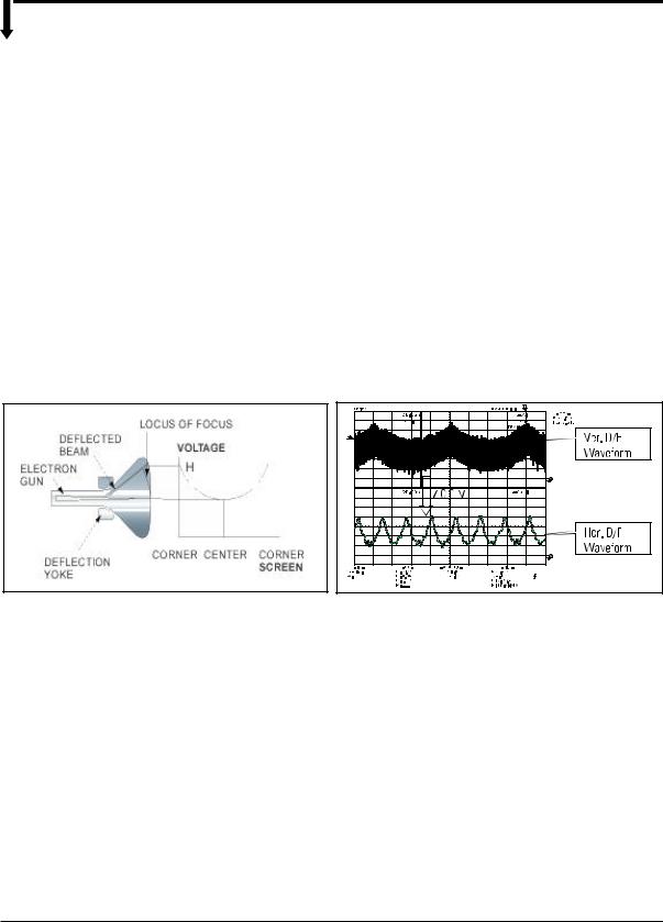
Most large-screen video display devices that are using CRT (including CDT) usually apply the Dynamic Focus (hereinafter D/F) circuit.
As CRT has non-spherical surface (perfect spherical surface = 1, non-spherical surface R>1), the distance that the electron beam emitted from the electron gun reaches to the center of CRT is different from the one that the electron beam reaches to the corners. (See Figure 1.)
Only the beam, which has the equal distance as the beam from the electron gun to the center of CRT surface, can maintain the optimum focus.
By this reason, focus dagradation at corners occurs inevitably.
To recover this, the speed of the electron beam injected into the corners of CRT should increase and the focus dagradation by the difference of distances can be compensated.
Increasing the voltage is used as a method of increasing the speed of the electron beam at the corners of screen.
In this case, an ideal D/F voltage waveform is the form of parabola where the center of screen has low voltage and the corners has the highest voltages.
The horizontal D/F waveform compensates the focus dagradation at left and right sides, but the vertical D/F waveform does at top and bottom sides.
The horizontal D/F and vertical D/F waveforms are separately created and mix two signals to compensate the focus of the whole screen.
And the vertical Dynamic Focus waveform is composed of the horizontal Dynamic Focus waveforms as much as the number of scanning lines. (See Figure 2.)
Fig. 1 Dynamic Focus Diagram (Horizantal) |
Fig. 2 H/V Dynamic Focus Waveform |
Samsung Electronics |
2-3 |

Reference Information
2-3 IC Line Up
2-3-1 Progressive |
|
2-4 |
Samsung Electronics |

Reference Information
Samsung Electronics |
2-5 |
Reference Information
2-4 MICOM IIC BUS LINE -UP
|
|
|
|
|
|
|
|
|
|
|
|
|
|
|
|
|
|
|
|
|
|
|
|
|
|
|
|
|
|
|
|
|
|
|
|
|
|
|
|
|
|
|
|
|
|
|
|
|
|
|
|
|
|
|
|
|
|
|
|
|
|
|
|
|
|
|
|
|
|
|
|
|
|
|
|
|
|
|
|
|
|
|
|
|
|
|
|
|
|
|
|
|
|
|
|
|
|
|
|
|
|
|
|
|
|
|
|
|
|
|
|
|
|
|
|
|
|
|
|
|
|
|
|
|
|
|
|
|
|
|
|
|
|
|
|
|
|
|
|
|
|
|
|
|
|
|
|
|
|
|
|
|
|
|
|
|
|
|
|
|
|
|
|
|
|
|
|
|
|
|
|
|
|
|
|
|
|
|
|
|
|
|
|
|
|
|
|
|
|
|
|
|
|
|
|
|
|
|
|
|
|
|
|
|
|
|
|
|
|
|
|
|
|
|
|
|
|
|
|
|
|
|
|
|
|
|
|
|
|
|
|
|
|
|
|
|
|
|
|
|
|
|
|
|
|
|
|
|
|
|
|
|
|
|
|
|
|
|
|
|
|
|
|
|
|
|
|
|
|
|
|
|
|
|
|
|
|
|
|
|
|
|
|
|
|
|
|
|
|
|
|
|
|
|
|
|
|
|
|
|
|
|
|
|
|
|
|
|
|
|
|
|
|
|
|
|
|
|
|
|
|
|
|
|
|
|
|
|
|
|
|
|
|
|
|
|
|
|
|
|
|
|
|
|
|
|
|
|
|
|
|
|
|
|
|
|
|
|
|
|
|
|
|
|
|
|
|
|
|
|
|
|
|
|
|
|
|
|
|
|
|
|
|
|
|
|
|
|
|
|
|
|
|
|
|
|
|
|
|
|
|
|
|
|
|
|
|
|
|
|
|
|
|
|
|
|
|
|
|
|
|
|
|
|
|
|
|
|
|
|
|
|
|
|
|
|
|
|
|
|
|
|
|
|
|
|
|
|
|
|
|
|
|
|
|
|
|
|
|
|
|
|
|
|
|
|
|
|
|
|
|
|
|
|
|
|
|
|
|
|
|
|
|
|
|
|
|
|
|
|
|
|
|
|
|
|
|
|
|
|
|
|
|
|
|
|
|
|
|
|
|
|
|
|
|
|
|
|
|
|
|
|
|
|
|
|
|
|
|
|
|
|
|
|
|
|
|
|
|
|
|
|
|
|
|
|
|
|
|
|
|
|
|
|
|
|
|
|
|
|
|
|
|
|
|
|
|
|
|
|
|
|
|
|
|
|
|
|
|
|
|
|
|
|
|
|
|
|
|
|
|
|
|
|
|
|
|
|
|
|
|
|
|
|
|
|
|
|
|
|
|
|
|
|
|
|
|
|
|
|
|
|
|
|
|
|
|
|
|
|
|
|
|
|
|
|
|
|
|
|
|
|
|
|
|
|
|
|
|
|
|
|
|
|
|
|
|
|
|
|
|
|
|
|
|
|
|
|
|
|
|
|
|
|
|
|
|
|
|
|
|
|
|
|
|
|
|
|
|
|
|
|
|
|
|
|
|
|
|
|
|
|
|
|
|
|
|
|
|
|
|
|
|
|
|
|
|
|
|
|
|
|
|
|
|
|
|
|
|
|
|
|
|
|
|
|
|
|
|
|
|
|
|
|
|
|
|
|
|
|
|
|
|
|
|
|
|
|
|
|
|
|
|
|
|
|
|
|
|
|
|
|
|
|
|
|
|
|
|
|
|
|
|
|
|
|
|
|
|
|
|
|
|
|
|
|
|
|
|
|
|
|
|
|
|
|
|
|
|
|
|
|
|
|
|
|
|
|
|
|
|
|
|
|
|
|
|
|
|
|
|
|
|
|
|
|
|
|
|
|
|
|
|
|
|
|
|
|
|
|
|
|
|
|
|
|
|
|
|
|
|
|
|
|
|
|
|
|
|
|
|
|
|
|
|
|
|
|
|
|
|
|
|
|
|
|
|
|
|
|
|
|
|
|
|
|
|
|
|
|
|
|
|
|
|
|
|
|
|
|
|
|
|
|
|
|
|
|
|
|
|
|
|
|
|
|
|
|
|
|
|
|
|
|
|
|
|
|
|
|
|
|
|
|
|
|
|
|
|
|
|
|
|
|
|
|
|
|
|
|
|
|
|
|
|
|
|
|
|
|
|
|
|
|
|
|
|
|
|
|
|
|
|
|
|
|
|
|
|
|
|
|
|
|
|
|
|
|
|
|
|
|
|
|
|
|
|
|
|
|
|
|
|
|
|
|
|
|
|
|
|
|
|
|
|
|
|
|
|
|
|
|
|
|
|
|
|
|
|
|
|
|
|
|
|
|
|
|
|
|
|
|
|
|
|
|
|
|
|
|
|
|
|
|
|
|
|
|
|
|
|
|
|
|
|
|
|
|
|
|
|
|
|
|
|
|
|
|
|
|
|
|
|
|
|
|
|
|
|
|
|
|
|
|
|
|
|
|
|
|
|
|
|
|
|
|
|
|
|
|
|
|
|
|
|
|
|
|
|
|
|
|
|
|
|
|
|
|
|
|
|
|
|
|
|
|
|
|
|
|
|
|
|
|
|
|
|
|
|
|
|
|
|
|
|
|
|
|
|
|
|
|
|
|
|
|
|
|
|
|
|
|
|
|
|
|
|
|
|
|
|
|
|
|
|
|
|
|
|
|
|
|
|
|
|
|
|
|
|
|
|
|
|
|
|
|
|
|
|
|
|
|
|
|
|
|
|
|
|
|
|
|
|
|
|
|
|
|
|
|
|
|
|
|
|
|
|
|
|
|
|
|
|
|
|
|
|
|
|
|
|
|
|
|
|
|
|
|
|
|
|
|
|
|
|
|
|
|
|
|
|
|
|
|
|
|
|
|
|
|
|
|
|
|
|
|
|
|
|
|
|
|
|
|
|
|
|
|
|
|
|
|
|
|
|
|
|
|
|
|
|
|
|
|
|
|
|
|
|
|
|
|
|
|
|
|
|
|
|
|
|
|
|
|
|
|
|
|
|
|
|
|
|
|
|
|
|
|
|
|
|
|
|
|
|
|
|
|
|
|
|
|
|
|
|
|
|
|
|
|
|
|
|
|
|
|
|
|
|
|
|
|
|
|
|
|
|
|
|
|
|
|
|
|
|
|
|
|
|
|
|
|
|
|
|
|
|
|
|
|
|
|
|
|
|
|
|
|
|
|
|
|
|
|
|
|
|
|
|
|
|
|
|
|
|
|
|
|
|
|
|
|
|
|
|
|
|
|
|
|
|
|
|
|
|
|
|
|
|
|
|
|
|
|
|
|
|
|
|
|
|
|
|
|
|
|
|
|
|
|
|
|
|
|
|
|
|
|
|
|
|
|
|
|
|
|
|
|
|
|
|
|
|
|
|
|
|
|
|
|
|
|
|
|
|
|
|
|
|
|
|
|
|
|
|
|
|
|
|
|
|
|
|
|
|
|
|
|
|
|
|
|
|
|
|
|
|
|
|
|
|
|
|
|
|
|
|
|
|
|
|
|
|
|
|
|
|
|
|
|
|
|
|
|
|
|
|
|
|
|
|
|
|
|
|
|
|
|
|
|
|
|
|
|
|
|
|
|
|
|
|
|
|
|
|
|
|
|
|
|
|
|
|
|
|
|
|
|
|
|
|
|
|
|
|
|
|
|
|
|
|
|
|
|
|
|
|
|
|
|
|
|
|
|
|
|
|
|
|
|
|
|
|
|
|
|
|
|
|
|
|
|
|
|
|
|
|
|
|
|
|
|
|
|
|
|
|
|
|
|
|
|
|
|
|
|
|
|
|
|
|
|
|
|
|
|
|
|
|
|
|
|
|
|
|
|
|
|
|
|
|
|
|
|
|
|
|
|
|
|
|
|
|
|
|
|
|
|
|
|
|
|
|
|
|
|
|
|
|
|
|
|
|
|
|
|
|
|
|
|
|
|
|
|
|
|
|
|
|
|
|
|
|
|
|
|
|
|
|
|
|
|
|
|
|
|
|
|
|
|
|
|
|
|
|
|
|
|
|
|
|
|
|
|
|
|
|
|
|
|
|
|
|
|
|
|
|
|
|
|
|
|
|
|
|
|
|
|
|
|
|
|
|
|
|
|
|
|
|
|
|
|
|
|
|
|
|
|
|
|
|
|
|
|
|
|
|
|
|
|
|
|
|
|
|
|
|
|
|
|
|
|
|
|
|
|
|
|
|
|
|
|
|
|
|
|
|
|
|
|
|
|
|
|
|
|
|
|
|
|
|
|
|
|
|
|
|
|
|
|
|
|
|
|
|
|
|
|
|
|
|
|
|
|
|
|
|
|
|
|
|
|
|
|
|
|
|
|
|
|
|
|
|
|
|
|
|
|
|
|
|
|
|
|
|
|
|
|
|
|
|
|
|
|
|
|
|
|
|
|
|
|
|
|
|
|
|
|
|
|
|
|
|
|
|
|
|
|
|
|
|
|
|
|
|
|
|
|
|
|
|
|
|
|
|
|
|
|
|
|
|
|
|
|
|
|
|
|
|
|
|
|
|
|
|
|
|
|
|
|
|
|
|
|
|
|
|
|
|
|
|
|
|
|
|
|
|
|
|
|
|
|
|
|
|
|
|
|
|
|
|
|
|
|
|
|
|
|
|
|
|
|
|
|
|
|
|
|
|
|
|
|
|
|
|
|
|
|
|
|
|
|
|
|
|
|
|
|
|
|
|
|
|
|
|
|
|
|
|
|
|
|
|
|
|
|
|
|
|
|
|
|
|
|
|
|
|
|
|
|
|
|
|
|
|
|
|
|
|
|
|
|
|
|
|
|
|
|
|
|
|
|
|
|
|
|
|
|
|
|
|
|
|
|
|
|
|
|
|
|
|
|
|
|
|
|
|
|
|
|
|
|
|
|
|
|
|
|
|
|
|
|
|
|
|
|
|
|
|
|
|
|
|
|
|
|
|
|
|
|
|
|
|
|
|
|
|
|
|
|
|
|
|
|
|
|
|
|
|
|
|
|
|
|
|
|
|
|
|
|
|
|
|
|
|
|
|
|
|
|
|
|
|
|
|
|
|
|
|
|
|
|
|
|
|
|
|
|
|
|
|
|
|
|
|
|
|
|
|
|
|
|
|
|
|
|
|
|
|
|
|
|
|
|
|
|
|
|
|
|
|
|
|
|
|
|
|
|
|
|
|
|
|
|
|
|
|
|
|
|
|
|
|
|
|
|
|
|
|
|
|
|
|
|
|
|
|
|
|
|
|
|
|
|
|
|
|
|
|
|
|
|
|
|
|
|
|
|
|
|
|
|
|
|
|
|
|
|
|
|
|
|
|
|
|
|
|
|
|
|
|
|
|
|
|
|
|
|
|
|
|
|
|
|
|
|
|
|
|
|
|
|
|
|
|
|
|
|
|
|
|
|
|
|
|
|
|
|
|
|
|
|
|
|
|
|
|
|
|
|
|
|
|
|
|
|
|
|
|
|
|
|
|
|
|
|
|
|
|
|
|
|
|
|
|
|
|
|
|
|
|
|
|
|
|
|
|
|
|
|
|
|
|
|
|
|
|
|
|
|
|
|
|
|
|
|
|
|
|
|
|
|
|
|
|
|
|
|
|
|
|
|
|
|
|
|
|
|
|
|
|
|
|
|
|
|
|
|
|
|
|
|
|
|
|
|
|
|
|
|
|
|
|
|
|
|
|
|
|
|
|
2-6 |
|
|
|
|
|
|
|
|
|
|
|
|
|
|
|
|
|
|
|
|
|
|
|
Samsung Electronics |
||||||

Specifications
3. Specifications
Broadcasting System |
NTSC |
|
|
|
|
|
|
Scanning System |
Progressive Scanning |
|
|
|
|
|
|
Tuning Range |
VHF : CH2 ~ CH13 |
|
|
|
|
|
|
Antenna Impedance |
75 ohm Unbalanced |
|
|
|
|
|
|
|
Video : 45.75 MHz |
|
|
Intermediate Frequency |
Sound : 42.25 MHz |
|
|
|
Chrominance Subcarrier : 42.17 MHz |
|
|
|
|
|
|
Sound Output |
STD : 10W |
|
|
|
|
|
|
|
MAX : 15W |
|
|
|
|
|
|
Rated Voltage |
120V / 60 Hz |
|
|
|
|
|
|
W/B Coordinates |
Hx : 266 |
Hy : 280 |
Y : 8.9 |
|
|
|
|
|
Lx : 268 |
Ly : 283 |
Y : 0.38 |
|
|
|
|
High Voltage |
29KV |
|
|
|
|
|
|
|
250V/6.3A |
|
|
FUSE |
CODE NO : 3601-000300 |
|
|
|
|
||
|
|
|
|
Power Consumption |
240W |
|
|
|
|
|
|
|
1002 X 450 X 1070mm |
|
|
Dimension |
39.4 X 17.7 X 42.1 inch |
|
|
|
|
||
|
|
|
|
Weight |
49Kg 108lbs |
|
|
|
|
|
|
Samsung Electronics |
3-1 |
Alignment and Adjustments
4. Alignment and Adjustments
4-1 When entering the service mode:
1.Turn on the TV, and then select “STANDARD”on the picture adjustment mode.
2.Turn off the TV (STAND-BY).
3.Enter the service mode by pressing the remote control keys in the following sequence :
Note : If necessary, re-do steps 1~3.
Initial display when the service mode is switched.
1. When a RF signal is received
SERVICE / Sim-474A
DEFLECTION
480P OFFSET
1080i OFFSET CONVERGENCE OFFSET VIDEO ADJUST 1 VIDEO ADJUST 2 VIDEO ADJUST 3 VIDEO ADJUST 4 OPTION (E3h 98h 0ch) RESET / 02-05-03
3. Service Mode Control Keys
MAIN MENU |
MENU DISPLAY |
|
|
CH UP/DOWN |
Select item by moving cursor |
|
|
VOL UP/DOWN |
Decrease or increase the adjustment values |
|
|
< PRECAUTIONS >
1.When EEPROM IC (IC902) is replaced, first connect the power cord and wait for about 4~5 seconds.
2.After replacing EEPROM IC (IC902), enter the Service mode. Next, enter the standard data or the previous EEPROM IC data before replacement. And then check and adjust any items related to Geometric, Picture, Option.
Samsung Electronics |
4-1 |

Alignment and Adjustments
4-2 Factory Data
DVI connection item is corresponded to DVI application model.
4-2-1 Defection
ITEM |
INITIAL DATA |
Range |
EEP-ROM Copy Data |
Remark |
||||
RF |
|
480P |
|
1080i |
||||
|
|
|||||||
|
|
|
|
|
|
|||
|
|
|
|
|
|
|
|
|
V Amp |
|
0 ~ 63 |
31 |
|
- |
|
- |
variable |
V Shift |
32 |
0 ~ 63 |
29 |
|
- |
|
- |
fix |
H EW |
|
0 ~ 63 |
31 |
|
- |
|
- |
variable |
H Shift |
32 |
0 ~ 63 |
31 |
|
- |
|
- |
fix |
V Linearity |
6 |
0 ~ 15 |
7 |
|
- |
|
- |
fix |
Upper Linearity |
7 |
0 ~ 15 |
0 |
|
- |
|
- |
fix |
Lower Linearity |
8 |
0 ~ 15 |
0 |
|
- |
|
- |
fix |
VSC |
3 |
0 ~ 15 |
7 |
|
- |
|
- |
fix |
H Parabola |
10 |
0 ~ 63 |
31 |
|
- |
|
- |
fix |
Upper Corner |
32 |
0 ~ 63 |
31 |
|
- |
|
- |
fix |
Lower Corner |
32 |
0 ~ 63 |
31 |
|
- |
|
- |
fix |
H Trapezium |
32 |
0 ~ 63 |
31 |
|
- |
|
- |
fix |
Bow |
32 |
0 ~ 63 |
31 |
|
- |
|
- |
fix |
Angel |
32 |
0 ~ 63 |
31 |
|
- |
|
- |
fix |
V Position |
32 |
0 ~ 63 |
31 |
|
- |
|
- |
fix |
CXA Left Blk |
35 |
0 ~ 63 |
35 |
|
- |
|
- |
fix |
CXA Right Blk |
35 |
0 ~ 63 |
35 |
|
- |
|
- |
fix |
|
|
|
|
|
|
|
|
|
4-2 |
Samsung Electronics |

Alignment and Adjustments
4-2-2 480P Offset
ITEM |
INITIAL DATA |
Range |
EEP-ROM Copy Data |
Remark |
||||
RF |
|
480P |
|
1080i |
||||
|
|
|||||||
|
|
|
|
|
|
|||
V Amp |
0 |
-63 ~ 63 |
- |
|
0 |
|
- |
variable |
V Shift |
0 |
-63 ~ 63 |
- |
|
0 |
|
- |
variable |
H EW |
0 |
-63 ~ 63 |
- |
|
0 |
|
- |
variable |
H Shift |
0 |
-63 ~ 63 |
- |
|
0 |
|
- |
variable |
V Linearity |
0 |
-15~ 15 |
- |
|
0 |
|
- |
fix |
Upper Linearity |
0 |
-15~ 15 |
- |
|
0 |
|
- |
fix |
Lower Linearity |
0 |
-15~ 15 |
- |
|
0 |
|
- |
fix |
VSC |
0 |
-15~ 15 |
- |
|
0 |
|
- |
fix |
H Parabola |
0 |
-63 ~ 63 |
- |
|
0 |
|
- |
fix |
Upper Corner |
0 |
-63 ~ 63 |
- |
|
0 |
|
- |
fix |
Lower Corner |
0 |
-63 ~ 63 |
- |
|
0 |
|
- |
fix |
H Trapezium |
0 |
-63 ~ 63 |
- |
|
0 |
|
- |
fix |
Bow |
0 |
-63 ~ 63 |
- |
|
0 |
|
- |
fix |
Angel |
0 |
-63 ~ 63 |
- |
|
0 |
|
- |
fix |
V Position |
0 |
-63 ~ 63 |
- |
|
0 |
|
- |
fix |
CXA Left Blk |
|
-63 ~ 63 |
- |
|
28 |
|
- |
fix |
CXA Right Blk |
|
-63 ~ 63 |
- |
|
36 |
|
- |
fix |
|
|
|
|
|
|
|
|
|
Samsung Electronics |
4-3 |
Alignment and Adjustments
4-2-3 1080i Offset
ITEM |
INITIAL DATA |
Range |
EEP-ROM Copy Data |
Remark |
||||
RF |
|
480P |
|
1080i |
||||
|
|
|||||||
|
|
|
|
|
|
|||
V Amp |
0 |
-63 ~ 63 |
- |
|
- |
|
0 |
variable |
V Shift |
0 |
-63 ~ 63 |
- |
|
- |
|
0 |
variable |
H EW |
0 |
-63 ~ 63 |
- |
|
- |
|
0 |
variable |
H Shift |
0 |
-63 ~ 63 |
- |
|
- |
|
0 |
fix |
V Linearity |
0 |
-15~ 15 |
- |
|
- |
|
0 |
|
Upper Linearity |
0 |
-15~ 15 |
- |
|
- |
|
0 |
|
Lower Linearity |
0 |
-15~ 15 |
- |
|
- |
|
0 |
|
VSC |
0 |
-15~ 15 |
- |
|
- |
|
0 |
|
H Parabola |
0 |
-63 ~ 63 |
- |
|
- |
|
0 |
|
Upper Corner |
0 |
-63 ~ 63 |
- |
|
- |
|
0 |
|
Lower Corner |
0 |
-63 ~ 63 |
- |
|
- |
|
0 |
|
H Trapezium |
0 |
-63 ~ 63 |
- |
|
- |
|
0 |
|
Bow |
0 |
-63 ~ 63 |
- |
|
- |
|
0 |
|
Angel |
0 |
-63 ~ 63 |
- |
|
- |
|
0 |
|
V Position |
0 |
-63 ~ 63 |
- |
|
- |
|
0 |
|
CXA Left Blk |
|
-63 ~ 63 |
- |
|
- |
|
63 |
|
CXA Right Blk |
|
-63 ~ 63 |
- |
|
- |
|
20 |
|
|
|
|
|
|
|
|
|
|
4-4 |
Samsung Electronics |

Alignment and Adjustments
4-2-4 CONVERGRNCE OFFSET
ITEM |
INITIAL DATA |
Range |
EEP-ROM Copy Data |
|
|||
|
|
|
|
Remark |
|||
RF |
480P |
1080i |
|
||||
|
|
|
|
||||
|
|
|
|
|
|
|
|
|
|
|
|
|
|
|
|
Offset Enable |
0 |
0 ~ 1 |
|
0 |
|
|
variable |
|
|
|
|
|
|
|
|
V Amp |
15 |
-63 ~ 63 |
|
15 |
|
|
variable |
|
|
|
|
|
|
|
|
V Shift |
0 |
-63 ~ 63 |
|
0 |
|
|
variable |
|
|
|
|
|
|
|
|
H EW |
15 |
-63 ~ 63 |
|
15 |
|
|
variable |
|
|
|
|
|
|
|
|
V Amp 1080i |
15 |
-63 ~ 63 |
|
15 |
|
|
variable |
|
|
|
|
|
|
|
|
V Shift 1080i |
0 |
-63 ~ 63 |
|
0 |
|
|
variable |
|
|
|
|
|
|
|
|
H EW 1080i |
15 |
-63 ~ 63 |
|
15 |
|
|
variable |
|
|
|
|
|
|
|
|
Samsung Electronics |
4-5 |

Alignment and Adjustments
4-2-5 VIDEO ADJUST 1
ITEM |
INITIAL DATA |
Range |
EEP-ROM Copy Data |
Remark |
||||||
RF-Copy |
|
W/B |
|
|
1080i |
|||||
|
|
|
||||||||
|
|
|
|
|
|
|
||||
|
|
|
|
Control Value |
|
|
|
|||
R Cutoff |
20 |
0 ~ 63 |
31 |
|
|
20 |
|
|
31 |
variable |
G Cutoff |
20 |
0 ~ 63 |
31 |
|
|
20 |
|
|
31 |
variable |
B Cutoff |
20 |
0 ~ 63 |
31 |
|
|
20 |
|
|
31 |
fix |
Color On/Off |
1 |
0 ~ 1 |
|
|
|
1 |
|
|
|
|
CR offset |
32 |
|
|
|
|
|
|
|
|
fix |
0 ~ 15 |
|
|
32 |
|
|
|
||||
CB offset |
32 |
0 ~ 15 |
|
|
32 |
|
|
|
fix |
|
R Driver |
31 |
0 ~ 15 |
20 |
|
|
|
20 |
variable |
||
|
31 |
|
||||||||
G Driver |
31 |
0 ~ 15 |
20 |
|
31 |
|
20 |
fix |
||
B Driver |
31 |
0 ~ 63 |
20 |
|
31 |
|
20 |
variable |
||
Sub Bright |
15 |
0 ~ 63 |
|
|
15 |
|
|
|
variable |
|
Sub Contrast |
7 |
0 ~ 15 |
|
|
7 |
|
|
|
variable |
|
Sub Color |
20 |
0 ~ 23 |
|
|
20 |
|
|
|
|
|
SubTint |
7 |
0 ~ 13 |
8(AV/SV/DVD/480P) |
|
10 |
fix |
||||
CTI Level |
1 |
0 ~ 3 |
1 (RF/AV/SV/DVD/480P/1080i) |
fix |
||||||
CDL AXIS |
2 |
0 ~ 3 |
|
|
2 |
|
|
|
fix |
|
LTI Level |
0 |
0 ~ 3 |
1(RF/AV/SV/DVD/480P) |
|
|
fix |
||||
|
|
2 |
||||||||
|
|
|
|
|
|
|
|
|
|
|
4-6 |
Samsung Electronics |
Alignment and Adjustments
4-2-6 VIDEO ADJUST 2
ITEM |
INITIAL DATA |
Range |
EEP-ROM Copy Data |
Remark |
|||
RF |
480P |
|
1080i |
||||
|
|||||||
|
|
|
|
|
|||
|
|
|
|
|
|
|
|
ABL Mode |
3 |
0 ~ 3 |
|
3 |
|
|
fix |
Gamma |
2 |
0 ~ 3 |
|
1 |
|
|
fix |
DPIC Level |
3 |
0 ~ 3 |
|
3 |
|
|
fix |
DC Trans |
3 |
0 ~ 3 |
|
1 |
|
|
fix |
ABL TH |
15 |
0 ~ 15 |
|
15 |
|
|
fix |
VM Level |
2 |
0 ~ 3 |
|
2 |
|
|
fix |
VM Coring |
0 |
0 ~ 3 |
0 |
|
|
|
|
|
|
|
|
||||
VM f0 |
0 |
|
|
|
|
|
fix |
0 ~ 3 |
2 (RF/AV/SV/DVD/480P) |
|
1 |
||||
VM Limit |
0 |
0 ~ 3 |
0 |
|
|
|
|
VM Delay |
0 |
0 ~ 3 |
0 (RF/AV/DVD) |
|
1 (480P) |
fix |
|
SHP CD |
1 |
0 ~ 3 |
1 |
|
|
|
|
|
|
|
|
||||
SHP f0 |
0 |
0 ~ 1 |
0 |
1 (AV/SV/DVD/Comp2) |
fix |
||
SHP f1 & P/O |
11 |
0 ~ 15 |
13 1 (RF/AV/SVHS/DVD/Comp2) |
fix |
|||
AKB Time |
13 |
0 ~ 31 |
16 |
|
|
|
|
|
|
|
|
||||
Y/C Delay |
30 |
0 ~ 31 |
30 |
|
|
|
|
PIP Y/C Delay |
30 |
0 ~ 31 |
30 |
|
|
|
|
BAND PASS F |
1 |
0 ~ 7 |
1 |
|
|
|
|
HIGH PASS F |
3 |
0 ~ 7 |
3 |
|
|
|
|
|
|
|
|
|
|
|
|
Samsung Electronics |
4-7 |

Alignment and Adjustments
4-2-7 VIDEO ADJUST 3
ITEM |
INITIAL DATA |
Range |
EEP-ROM Copy Data |
|
|||
|
|
|
|
Remark |
|||
RF |
480P |
1080i |
|
||||
|
|
|
|
||||
|
|
|
|
|
|
|
|
VSU |
2 |
0 ~ 15 |
2 |
- |
- |
|
|
|
|
|
|
|
|
|
|
Melody Volume |
4 |
0 ~ 20 |
4 |
- |
- |
|
|
|
|
|
|
|
|
|
|
H Comp |
0 |
0 ~ 15 |
0 |
- |
- |
|
|
|
|
|
|
|
|
|
|
V Comp |
0 |
0 ~ 15 |
0 |
- |
- |
|
|
|
|
|
|
|
|
|
|
Pin Comp |
0 |
0 ~ 15 |
0 |
- |
- |
|
|
|
|
|
|
|
|
|
|
AFC Comp |
0 |
0 ~ 7 |
0 |
- |
- |
|
|
|
|
|
|
|
|
|
|
Sync Comp |
0 |
0 ~ 1 |
0 |
- |
- |
|
|
|
|
|
|
|
|
|
|
NR Off Value |
5 |
0 ~ 9 |
5 |
- |
- |
|
|
|
|
|
|
|
|
|
|
V-Mute(x100ns) |
8 |
0 ~ 10 |
8 |
- |
- |
|
|
|
|
|
|
|
|
|
|
4-8 |
Samsung Electronics |
Alignment and Adjustments
4-2-8 VIDEO ADJUST 4
ITEM |
INITIAL DATA |
Range |
EEP-ROM Copy Data |
Remark |
|||
|
|
|
|||||
RF |
480P |
1080i |
|||||
|
|
|
|
||||
|
|
|
|
|
|
|
|
System RF |
1 |
0 ~ 3 |
1 |
|
|
|
|
|
|
|
|
|
|
|
|
System_VSD_480P |
1 |
0 ~ 3 |
|
1 |
|
|
|
|
|
|
|
|
|
|
|
System_1080i |
2 |
0 ~ 3 |
|
|
2 |
fix |
|
|
|
|
|
|
|
|
|
Shp_Fo_VSD_480P |
1 |
0 ~ 1 |
|
1 |
|
|
|
|
|
|
|
|
|
|
|
HPF_VSD |
3 |
0 ~ 7 |
3 |
3 (AVS/SV/DVD) |
|
||
|
|
|
|
|
|
|
|
BPF_VSD |
1 |
0 ~ 7 |
1 |
1 (AVS/SV/DVD) |
fix |
||
|
|
|
|
|
|
|
|
Chrm_bdwth_RF |
28 |
0 ~ 63 |
28 |
|
|
fix |
|
|
|
|
|
|
|
|
|
Chrm_bdwth_Video |
28 |
0 ~ 63 |
28 |
|
|
fix |
|
|
|
|
|
|
|
|
|
Chrm_bdwth_Svideo |
30 |
0 ~ 63 |
30 |
|
|
fix |
|
|
|
|
|
|
|
|
|
Chrm_bdwth_DVD |
28 |
0 ~ 63 |
28 |
|
|
fix |
|
|
|
|
|
|
|
|
|
IF_Comp_RF |
2 |
0 ~ 7 |
2 |
|
|
fix |
|
|
|
|
|
|
|
|
|
IF_Comp_Video |
4 |
0 ~ 7 |
4 |
|
|
fix |
|
|
|
|
|
|
|
|
|
IF_Comp_Svideo |
5 |
0 ~ 7 |
5 |
|
|
fix |
|
|
|
|
|
|
|
|
|
IF_Comp_DVD |
4 |
0 ~ 7 |
4 |
|
|
fix |
|
|
|
|
|
|
|
|
|
VM_Delay_480P |
1 |
0 ~ 3 |
|
1 |
|
fix |
|
|
|
|
|
|
|
|
|
Samsung Electronics |
4-9 |

Alignment and Adjustments
4-2-9 OPTION
|
|
|
HCM4216W,HCM4215W, |
HCM422W,HCM473WB |
ITEM |
INITIAL DATA |
Range |
HCL4715WB,HCM4715W |
|
|
|
|
(PCL5415RB,PCM5415R) |
(PCL545RB,PCM545R) |
|
|
|
HCM553WB |
|
|
|
|
HCM5525WB,PTH5598W |
|
|
|
|
|
|
CRT |
WIDE |
WIDE ↔ 4:3 |
WIDE(4:3) |
WIDE(4:3) |
PIP |
ON |
ON ↔ OFF |
ON |
ON |
3D-Comb Filter |
OFF |
ON ↔ OFF |
OFF |
ON |
Blue Screen |
OFF |
ON ↔ OFF |
ON |
ON |
BBE Effect |
ON |
ON ↔ OFF |
ON |
ON |
Auto power On |
ON |
ON ↔ OFF |
ON |
ON |
System |
CT |
CT (EN+SP+ER)→CT-A(E+SP+F) |
CT |
CT |
Virtual Dolby |
OFF |
ON ↔ OFF |
OFF |
OFF |
ACS |
ON |
ON ↔ OFF |
ON |
ON |
V chip (CT,CTA) |
ON |
ON ↔ OFF |
ON |
ON |
V chop Area |
USA |
USA |
USA |
USA |
Sub Woofer |
OFF |
ON ↔ OFF |
OFF |
OFF |
No Sync Mute |
ON |
ON ↔ OFF |
ON |
ON |
DVI |
ON |
ON ↔ OFF |
OFF |
OFF |
AGC |
OFF |
ON ↔ OFF |
OFF |
OFF |
Tubo Effect |
OFF |
ON ↔ OFF |
OFF |
OFF |
Burst Screen |
OFF |
ON ↔ OFF |
OFF |
OFF |
DW Multi |
Large |
Large ↔ Double |
Large |
Double |
Letter Box |
ON |
ON ↔ OFF |
ON |
ON |
|
|
|
|
|
4-10 |
Samsung Electronics |

Alignment and Adjustments
4-3 Screen Change (When adjusting I2C Bus Geometric items)
1 V SHIFT |
6 V SIZE |
|
|
|
|
|
|
|
|
|||||||||||||||||
|
|
|
|
|
|
|
|
|
|
|
|
|
|
|
|
|
|
|
|
|
|
|
|
|
|
|
|
|
|
|
|
|
|
|
|
|
|
|
|
|
|
|
|
|
|
|
|
|
|
|
|
|
|
|
|
|
|
|
|
|
|
|
|
|
|
|
|
|
|
|
|
|
|
|
|
|
|
|
|
|
|
|
|
|
|
|
|
|
|
|
|
|
|
|
|
|
|
|
|
|
|
|
|
|
|
|
|
|
|
|
|
|
|
|
|
|
|
|
|
|
|
|
|
|
|
|
|
|
|
|
|
|
|
|
2 V LINEARITY |
|
|
|
|
|
|
|
|
|
|
|
|
|
7 V - S - CORRECTION |
|
|
||||||||||||||||||||
|
|
|
|
|
|
|
|
|
|
|
|
|
|
|
|
|
|
|
|
|
|
|
|
|
|
|
|
|
|
|
|
|
|
|
|
|
|
|
|
|
|
|
|
|
|
|
|
|
|
|
|
|
|
|
|
|
|
|
|
|
|
|
|
|
|
|
|
|
|
|
|
|
|
|
|
|
|
|
|
|
|
|
|
|
|
|
|
|
|
|
|
|
|
|
|
|
|
|
|
|
|
|
|
|
|
|
|
|
|
|
3 H SIZE
8 |
PIN PHASE |
4 PIN AMP |
|
|
|
|
|
|
|
|
|
9 H SHIFT |
|
|
|
|
|
|
|
|
|
|
|
|
|
|
|
|
|
|
|
|
|
|
|
|
|
|
|
|
|
|
|
|
|
|
|
|
|
|
|
|
|
|
|
|
|
|
|
|
|
|
|
|
|
|
|
|
|
|
|
|
|
|
|
|
|
|
|
|
|
|
|
|
|
|
|
|
|
|
|
|
|
|
|
|
|
|
|
|
|
5 |
V ANGLE |
10 V BOW
Samsung Electronics |
4-11 |
Alignment and Adjustments
4-4 Other Adjustments
4-4-1 Screen Adjustment
1.Warm up the TV for at least 30 minutes.
2.Select the “ STANDARD” Video mode.
3.Turn to the Video Mode (No Signal) using a remote-control.
4.Connect an oscilloscope to RK,GK,BK.
5.Adjust the VR (VR501, VR531, VR561) screen so that RK, GK, BK pulse is 20Vp-p each. (Turn the R,G,B VR screen fully counterclockwise in the area of each flyback line.)
4-4-2 White Balance Adjustment
1.Select the “STANDARD” video mode.
2.Input 100% white pattern.
3.In the stand-by mode, press the remote-control keys in the following sequence:
4.Warm up the TV for at least 30 minutes.
5.Input a 10-step signal.
6.R-cut off, B-cut off, and G-cut off by pressing the Volume  keys.
keys.
7.Adjust the low light with viewing the dark side of the screen.
8.Select R-drive, G-drive, and B-drive by pressing the Volume  keys.
keys.
9.Adjust the high light with viewing the light side of the screen.
10.If necessary, redo adjustments 6~9.
11.Press the Menu key to exit.
4-4-3 Sub-Brightness Adjustment
1.Input a sub-brightness adjustment signal. (TOSHIBA PATTERN)
2.In the stand-by mode, press the remote-control keys in the following sequence :
3.Select SBT by pressing the Volume  keys.
keys.
4.Adjust so that the 63 step on the right side of the screen is not seen (Use the Volume 


keys).
5. Press the Menu key to exit.
4-4-4 High Voltage (29KV) Check
PRECAUTION
1.Input a lion head pattern.
2.Select “STANDARD” video mode.
3.Warm up the TV for at least 10 minutes.
4.Use a 1000:1 probe.
ADJUSTMENT
1.Connect the (+) terminal of the 1000:1 probe to the high voltage distributor and the (-) terminal to GND (located on the deflection board).
2.Adjust RR471S (located on the deflection board) so that the digital meter indicates DC 29V ± 0.1V.
4-4-5 F.S. (Fail Safe) Adjustment
Note : The finished product has a well-mounted VR (RR402S).
If necessary, do the F.S. adjustments in the following sequence.
1.Use a digital multimeter.
2.Connect the digital multimeter to the JIG pin (DZ482S) terminals
3.Adjust VR (RR402S) so that the voltage becomes 2.25V.
4.After the adjustments are complete, be sure to mount VR (RR402S) correctly.
4-12 |
Samsung Electronics |

4-4-6 F.S. (Fail Safe) Circuit Check
Note : The F.S. Circuit check must be performed after servicing.
1.Turn on the TV.
2.Select the “STANDARD” video mode.
3.Short F/S Test point (located on the SUB PCB). Then, both sound and picture disappear. (Note: Even if the shorted terminals are removed, both sound and
picture do not appear. This proves the F.S. circuit is working. )
4.To restore both sound and picture, turn off the TV and reset it after about 30 seconds.
4-4-7 Static Focus Adjustment
PRECAUTION
1.Select the “STANDARD” video mode.
2.Input a crosshatch pattern.
3.Cover the lenses that are not being adjusted.
4.Connect a convergence jig and read data.
5.Adjust the lens for best focus. (See Fig, 4-1)
STATIC FOCUS (CONTINUED)
Vary the focus pack VR (Red, Blue) on the front cabinet. Adjust the TV for best possible focus around the center of the crosshatch pattern, without losing overall screen balance. Figure Crosshatch Pattern
Examine these points together.
Examine these points together
Fig. 4-1 Crosshatch Pattern.
Alignment and Adjustments
4-4-8 Lens Focus Adjustment
PRECAUTIONS
1.Do this adjustment after the static focus adjustment and the tilt adjustment.
2.Select the “STANDARD” video mode. (Contrast:100, Brightness:50)
3.Input a crosshatch pattern.
ADJUSTMENT
1.Loosen the lens screws.
2.Cover the two lenses that are not being adjusted.
3.Adjust the lens, observing the color aberration vertically and horizontally within 3 blocks of the center of the crosshatch pattern.
4.When the lens is turned clockwise, the color aberration will change as follows:
Lens |
Color Aberration Change |
R |
Orange - Crimson |
G |
Blue - Red |
B Purple - Green
5.Green lens adjustment:
Set the lens at the point where Blue just changes to Red. If the color aberration is irregular throughout the picture screen, adjust the lens to show Red color aberration (approximately 1~3 mm area) within a 3-block grid around the horizontal center-line. If the color aberration is irregular, adjust the lens as shown in the diagram below. (Accurate alignment of Green is important for overall color quality.)
6.Red lens adjustment
Set the Red lens at the point where Orange becomes Crimson.
7.Blue lens adjustment
Set the Blue lens at the point where Purple becomes Green.
P
L1 |
L2 |
RED ABERRATION BLUE ABERRATION
L1, L2_< P
Fig. 4-2 Color Aberration
Samsung Electronics |
4-13 |
Alignment and Adjustments
4-5 Beam alignment Adjustments
1.Select the “STANDARD” video mode.
2.Warm up the set at least for 10 minutes.
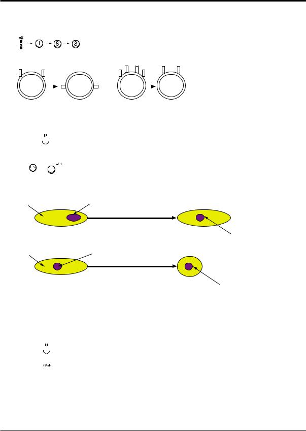
3.Enter the Convergence mode by pressing the remote control buttons in the following sequence
:
4. Set the Beam Alignment Adjustment CY to Zero magnetic field area.
|
|
|
|
|
|
(Creation of CPM Zero Magnet) |
(Creation of the 2-pole/4-pole zero magnets) |
||||
5.Check the squarewave at the point where the focus is misaligned (Use an audio oscillator).
6.Press the  button on the remote control, and a vibrating dot-pattern appears.
7.Adjust the Focus-pack VR for defocusing.
8.Mute the other patterns (R/B) other than G-PATTERN.
(Use |
/ |
buttons on the remote control.) |
9.Adjust the 2, 4 polarities of VM-COIL as shown in figure below.
10.Adjust the G-Focus until any light around the core disappears.
G-FOCUS |
CORE |
Varying the 2-pole of VM
(Varying G-Focus Pack) |
|
G-FOCUS |
CORE |
|
Varying the 4-pole of VM
(When VM 2-Pole Adjustment is completed)
(Positioning the Core in the Center)
(Adjust until the light around the core becomes a circle)
11.Adjust G-Focus so that the surrounding flash can disappear from the spot.
12.After G-Focus adjustments are complete, adjust R-Focus as above procedures.
13.The B-CRT adjustments can be omitted because the variance of beam focus is small. (Only Vm-coil is mounted.)
14.Adjust the Focus-pack VR for fine focusing.
15.Press the  button on the remote control, and the mode changes to the Convergence Adjustment mode.
16.Press the  button on the remote control to return to normal viewing.
4-14 |
Samsung Electronics |

Alignment and Adjustments
4-6 Hige Voltage Part
4-6-1 PWM REG Circuit |
3. PWM IC OSC Sync Lock |
For the existing high voltage REG circuit (input voltage variation type), a dynamic REG response is not provided. So it is difficult for both beam linearity and uniformity in screen size to be maintained on the screen with rapidly changing beams.
A PWM (Pulse Width Modulation) type of high voltage, however, provides the maintenance of beam linearity and uniformity in screen size via a quick response to beam change by performing sync lock every 1H line, and detecting beam fluctuation at 1H line, and then controlling the IC current of high voltage output circuit.
1. High Voltage Fluctuation Detect (DC Detect)
FBT pin 11 detects DC high voltage fluctuation. The detected DC high voltage value is input to PWM IC471 pin1 through R473, VR471, R471, and then it is input to a differential AMP circuit that differentiates the gap after comparing with the reference voltage input to pin2.
2. High Voltage Fluctuation Detect (AC Detect)
To check AC high voltage fluctuation, the output from FBT is detected by using a capacitor inside the high voltage distributor. The detection of AC high voltage fluctuation,
a detection of dynamic beam current change is required in order to keep beam linearity and uniformity in size.
Regarding the capacitor, a capacity of less than 3000P should be applied to a PWM type. (The existing type needs a capacity of about 6000P.) AC detect circuit eliminates unnecessary high frequency by using C476, D472. Also, AC gain is limited to + / - 0.7V (D472). This AC gain is combined with the detection value of DC high voltage fluctuation by using C478.
A PWM type IC needs sync lock for PWM pulse and horizontal scan line.
The standard time constant of OSC circuit is determined by C487, R475 (PWM IC pins 5 and 6). And the standard OSC frequency is about 27 kHz . The horizontal frequency of scan line is 31.5kHz(NT), 3375kHz(DTV), 15.75kHz(Interface), so sync lock for this horizontal frequency should be performed using sync lock circuit. The sync lock circuit consists of Q481(Tr KSC815-Y), D479, D478, and C492. The input AFC signal is connected to PWM IC pin 5 through D479 so that it can be negative Trig.
OSC : 27KHz
AFC Waveform : 31.5KHz(NT)
Locked OSC Waveform : 31.5KHz
4. Dead Time (HV Protect)
Dead Time (PWM IN pin4) consists of C481, delays high voltage for a certain time to soft start in power on, a x-ray protection circuit.
The voltage of Dead Time is detected by FBT pin7 and through DC Feedback. The normal voltage of Dead Time is +27V. When high voltage increases, however, detected voltage is in proportion to high voltage. Then, the detected voltage is applied to ICR01S(TL431).
If the voltage is over 2.5V (normal:about 2.25V), TL431 turns ON, the base port of QR401S becomes low, and then an emitter current flows. At this time, a high voltage protection point is set. When QR401S turns ON, high voltage is applied to PWM IC pin4 and then muted.
Samsung Electronics |
4-15 |

Alignment and Adjustments
5. Output Circuit
The voltages, which are detected form an error detection circuit of PWM IC (Differential AMP) and Dead Time, each is applied to PWM conparator . Due to these detection coltages, Q1, Q2 (Output TR) parallel operate. Q482 (External TR), however, functions as a buffer; natches inpedance between the output port of PWM IC and the final output TR(IRFS640). The PWM pulse (applied to the final output FET (IRFS640 GATE) varies the IC current of high voltage TR(Q473) by adjusting the load impedance of starage Trans (T431). Due to this variation of current, the gain for Q473 emitter pulse changes T444(FBT)makes this emitter pulse became high voltage. Such change keeps both dynamic and static changes fixed. The output waveform of high valtage TR emitter is as shown in the figure below.
6. Paraneters according to beam
To maintain the set high voltage value (31kV), parmaters such as +Ve (DC), Vcp High Voltage change (See the table below).
Factor of high |
|
|
Parameters |
|
|
|
|
Width of FET |
|
|
High |
||
voltage change |
+ Ve (DC) |
Vcp |
||||
Gate Pulse |
Voltage |
|||||
|
|
|
|
|||
Beam |
|
|
|
|
|
|
(High voltage |
) |
|
|
|
|
|
Beam |
|
|
|
|
|
|
(High voltage |
) |
|
|
|
|
|
7. Response Waveform
To reduce unstable high voltage fluctuation, the existing high voltage type REG circuit controls dynamic fluctuation by using C-block capacitor. But, it can't detect actual dynamic fluctuation. Also, its velocity of response to static fluctuation is late because +B power supply changes per
about 1V. A PWM modulation type REG detects static, dynamic high voltage fluctuation for only Ton Time (when the current of the output TR collector flows) each 1H, and modulates the width of PWM pulse. So, this PWM type has better improvement in the characteristic of high voltage REG as compared to the existing type.
High Voltage Drive Base Current
GND |
|
|
|
Ton |
Toff |
GND |
PWM Variation tange |
|
|
|
PWM Input Waveform of FET GATE
8.Application Effects
1)Improvement of horizontal size fluctuation
2)Linearity improved
3)Embodiment of X-ray protection circuit
The figures below show characteristics when a PWM high voltage REG circuit is applied.
High Voltage
Beam
High Voltage OFF
High Voltage REG ON
BLACK
WHITE
PWM type
When a Toshiba Pattern is recrived, the screen is displayed as shown in figute side
Existing type
4-16 |
Samsung Electronics |
Alignment and Adjustments
4-7 Screen-Jig
4-7-1 HCM4215W/HCM422W/HCM4216W (NORMAL MODE)
42W5ScreenSize:X932,Y524(X:378=9*2+30*12,Y:440=28*2+64*6)
22.19mm |
73.97mm |
2 2 .1 9 m m |
||||||||
|
|
|
|
|
|
|
|
|
|
|
|
|
|
|
|
|
|
|
|
|
|
|
|
|
|
|
|
|
|
|
|
|
|
|
|
|
|
|
|
|
|
|
|
3 3 .3 5 m m
7 6 .2 2 m m
42W5 TV
3 3 .3 5 m m
4-7-2 HCM4215W/HCM422W/HCM4216W (DTV MODE)
42W5 DTV Mode : X 932, Y 524 (X:408=18*2+31*12, Y:488=40*2+68*6) |
|
|
|
|||||||||
41.12mm |
70.81mm |
41.12mm |
||||||||||
|
|
|
|
|
|
|
|
|
|
|
|
|
|
|
|
|
|
|
|
|
|
|
|
|
|
|
|
|
|
|
|
|
|
|
|
|
|
|
|
|
|
|
|
|
|
|
|
|
|
|
|
4 2 .9 5 m m |
|
|
|
|
|
|
|
|
||||
|
|
|
|
|
|
|
|
|
|
|
|
|
|
|
|
|
|
|
|
|
|
||||
73.02mm |
|
|
|
|
|
|
|
|
|
|||
|
|
|
|
|
|
|
|
|
|
|
|
|
 42W5 DTV
42.95mm
Samsung Electronics |
4-17 |

Alignment and Adjustments
4-7-3 473W/4715W (NORMAL MODE)
4-7-4 473W/4715W (DTV MODE)
4-18 |
Samsung Electronics |
 Loading...