


HLT6187SX-XAA
Table of contents
 Loading...
DLP TV
Chassis : L67A(N)_Laurel
Model : HLT6187SX/XAA
DLP TV FEATURES
■
HD Built in TV
■
■
NTSC/ATSC Tuner Embedded
■
3D Ready
■
■
PC input
■
3HDMI Interface Adopted
■
■
Digital Audio output (OPTICAL) jack
■
Firmware upgrade by USB Port
SERVICE
Manual
HL-T6187S
Refer to the service manual in the GSPN (see the rear cover) for the more information.
This Service Manual is a property of Samsung Electronics Co.,Ltd.
Any unauthorized use of Manual can be punished under applicable
International and/or domestic law.
© Samsung Electronics Co., Ltd. Mar. 2007
Printed in Korea
AA82-04029A
Area Web Site
North America service.samsungportal.com
Latin America latin.samsungportal.com
CIS cis.samsungportal.com
Europe europe.samsungportal.com
China china.samsungportal.com
Asia asia.samsungportal.com
Mideast & Africa mea.samsungportal.com
GSPN (Global Service Partner Network)

Table of Contents
Chapter 1 Precaution
■ 1-1 Safety Precautions . . . . . . . . . . . . . . . . . . . . . . . . . . . . . . . . . . . . . . . . . . . . . . . . . . . . . . . . . . . 1-1
■ 1-2 Servicing Precautions . . . . . . . . . . . . . . . . . . . . . . . . . . . . . . . . . . . . . . . . . . . . . . . . . . . . . . . . 1-3
■ 1-3 Static Electricity Precautions . . . . . . . . . . . . . . . . . . . . . . . . . . . . . . . . . . . . . . . . . . . . . . . . . . . 1-4
■ 1-4 Installation Precautions . . . . . . . . . . . . . . . . . . . . . . . . . . . . . . . . . . . . . . . . . . . . . . . . . . . . . . . 1-5
Chapter 2 Product Specification
■ 2-1 Product Features . . . . . . . . . . . . . . . . . . . . . . . . . . . . . . . . . . . . . . . . . . . . . . . . . . . . . . . . . . . . 2-1
■ 2-2 Key Features . . . . . . . . . . . . . . . . . . . . . . . . . . . . . . . . . . . . . . . . . . . . . . . . . . . . . . . . . . . . . . . 2-3
■ 2-3 Specifications Analysis . . . . . . . . . . . . . . . . . . . . . . . . . . . . . . . . . . . . . . . . . . . . . . . . . . . . . . . . 2-5
■ 2-4 Accessories . . . . . . . . . . . . . . . . . . . . . . . . . . . . . . . . . . . . . . . . . . . . . . . . . . . . . . . . . . . . . . . . 2-6
Chapter 3 Alignment & Adjustment
■ 3-1 Service Instruction . . . . . . . . . . . . . . . . . . . . . . . . . . . . . . . . . . . . . . . . . . . . . . . . . . . . . . . . . . . 3-1
■ 3-2 How to Access Service Mode . . . . . . . . . . . . . . . . . . . . . . . . . . . . . . . . . . . . . . . . . . . . . . . . . . . 3-2
■ 3-3 Factory Data . . . . . . . . . . . . . . . . . . . . . . . . . . . . . . . . . . . . . . . . . . . . . . . . . . . . . . . . . . . . . . . . 3-3
■ 3-4 Service Adjustment . . . . . . . . . . . . . . . . . . . . . . . . . . . . . . . . . . . . . . . . . . . . . . . . . . . . . . . . . . 3-17
■ 3-5 Software Upgrade . . . . . . . . . . . . . . . . . . . . . . . . . . . . . . . . . . . . . . . . . . . . . . . . . . . . . . . . . . . 3-21
■ 3-6 Replacements & Calibration . . . . . . . . . . . . . . . . . . . . . . . . . . . . . . . . . . . . . . . . . . . . . . . . . . . . 3-22
Chapter 4 Exploded View & Part List
■ 4-1 HLT6187SX/XAA . . . . . . . . . . . . . . . . . . . . . . . . . . . . . . . . . . . . . . . . . . . . . . . . . . . . . . . . . . . . 4-1
Chapter 5 Electrical Part List
■ 5-1 HLT6187SX/XAA Service Item . . . . . . . . . . . . . . . . . . . . . . . . . . . . . . . . . . . . . . . . . . . . . . . . . . 5-1
Chapter 6 Troubleshooting
■ 6-1 Checkpoints by Error Mode . . . . . . . . . . . . . . . . . . . . . . . . . . . . . . . . . . . . . . . . . . . . . . . . . . . . 6-1
■ 6-2 Troubleshooting Procedures by Error Modes . . . . . . . . . . . . . . . . . . . . . . . . . . . . . . . . . . . . . . . 6-6
Chapter 7 Block Diagram
■ 7-1 Overall Block Diagram . . . . . . . . . . . . . . . . . . . . . . . . . . . . . . . . . . . . . . . . . . . . . . . . . . . . . . . . 7-1
■ 7-2 Partial Block Diagram . . . . . . . . . . . . . . . . . . . . . . . . . . . . . . . . . . . . . . . . . . . . . . . . . . . . . . . . . 7-2

Chapter 8 Wiring Diagram
■ 8-1 Overall Wiring . . . . . . . . . . . . . . . . . . . . . . . . . . . . . . . . . . . . . . . . . . . . . . . . . . . . . . . . . . . . . . . 8-1
■ 8-2 Main Board Layout . . . . . . . . . . . . . . . . . . . . . . . . . . . . . . . . . . . . . . . . . . . . . . . . . . . . . . . . . . . 8-3
Chapter 9 PCB Diagram
■ 9-1 Power Board . . . . . . . . . . . . . . . . . . . . . . . . . . . . . . . . . . . . . . . . . . . . . . . . . . . . . . . . . . . . . . . 9-1
■ 9-2 Sub-Power Board . . . . . . . . . . . . . . . . . . . . . . . . . . . . . . . . . . . . . . . . . . . . . . . . . . . . . . . . . . . . 9-2
■ 9-3 Main Board . . . . . . . . . . . . . . . . . . . . . . . . . . . . . . . . . . . . . . . . . . . . . . . . . . . . . . . . . . . . . . . . . 9-3
■ 9-4 Jack Board . . . . . . . . . . . . . . . . . . . . . . . . . . . . . . . . . . . . . . . . . . . . . . . . . . . . . . . . . . . . . . . . . 9-4
■ 9-5 DMD Board . . . . . . . . . . . . . . . . . . . . . . . . . . . . . . . . . . . . . . . . . . . . . . . . . . . . . . . . . . . . . . . . 9-5
■ 9-6 LED Driver Board . . . . . . . . . . . . . . . . . . . . . . . . . . . . . . . . . . . . . . . . . . . . . . . . . . . . . . . . . . . . 9-6
Chapter 10 Schematic Diagram
■ 10-1 Main Board . . . . . . . . . . . . . . . . . . . . . . . . . . . . . . . . . . . . . . . . . . . . . . . . . . . . . . . . . . . . . . . . 10-1
■ 10-2 Jack Board . . . . . . . . . . . . . . . . . . . . . . . . . . . . . . . . . . . . . . . . . . . . . . . . . . . . . . . . . . . . . . . . 10-19
■ 10-3 DMD Board . . . . . . . . . . . . . . . . . . . . . . . . . . . . . . . . . . . . . . . . . . . . . . . . . . . . . . . . . . . . . . . 10-20
■ 10-4 Power . . . . . . . . . . . . . . . . . . . . . . . . . . . . . . . . . . . . . . . . . . . . . . . . . . . . . . . . . . . . . . . . . . . . 10-30
Chapter 11 Operation Instruction & Installation
■ 11-1 Product Features and Functions . . . . . . . . . . . . . . . . . . . . . . . . . . . . . . . . . . . . . . . . . . . . . . . 11-1
■ 11-2 New Features . . . . . . . . . . . . . . . . . . . . . . . . . . . . . . . . . . . . . . . . . . . . . . . . . . . . . . . . . . . . . . 11-6
Chapter 12 Disassembly & Reassembly
■ 12-1 Overall Disassembly & Reassembly . . . . . . . . . . . . . . . . . . . . . . . . . . . . . . . . . . . . . . . . . . . . 12-1
Chapter 13 Circuit Description
■ 13-1 Overall Block Description . . . . . . . . . . . . . . . . . . . . . . . . . . . . . . . . . . . . . . . . . . . . . . . . . . . . . 13-1
■ 13-2 Partial Block Description . . . . . . . . . . . . . . . . . . . . . . . . . . . . . . . . . . . . . . . . . . . . . . . . . . . . . 13-2
■ 13-3 New Circuit Description . . . . . . . . . . . . . . . . . . . . . . . . . . . . . . . . . . . . . . . . . . . . . . . . . . . . . . 13-6
Chapter 14 Reference Information
■ 14-1 Other issues related to other products . . . . . . . . . . . . . . . . . . . . . . . . . . . . . . . . . . . . . . . . . . . 14-1
■ 14-2 Technical Terms . . . . . . . . . . . . . . . . . . . . . . . . . . . . . . . . . . . . . . . . . . . . . . . . . . . . . . . . . . . . 14-3
1. Make sure all protective devices are properly installed
including non-metallic handles and compartment covers
when installing or re-installing the chassis or chassis
assemblies.
2. Make sure that no gaps exist between the cabinets for
children to insert their fingers in to prevent children from
receiving electric shocks.
Errors may occur when the resistance is below 1.0 ㏁ or
over 5.2 ㏁.
In these cases, make sure that the device is repaired
before sending it back to the customer.
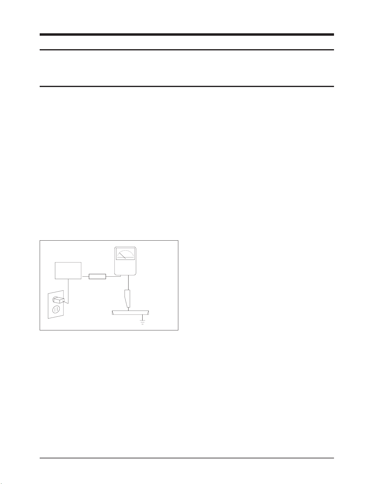
3. Check for Electricity Leakage (Figure 1-1)
Warning: Do not use an insulated transformer for check-
ing the leakage. Use only those current leakage testers
or mirroring systems that comply with ANSIC 101.1 and
the Underwriter Laboratory's specifications (UL1410,
59.7).
Fig. 1-1 AC Leakage Test
4. A high voltage is maintained within the specified limits
using safety parts, calibration and tolerances. When
voltage exceeds the specified limits, check each special
part.
5. Warning for Engineering Changes:
Never make any changes or additions to the circuit
design or the internal part for this product.
Ex: Do not add any audio or video accessory
connectors. This might cause physical damage.
Furthermore, any changes or additions to the original
design/engineering will invalidate the warranty.
6. Warning - Hot Chassis:
Some TV chassis are directly connected to one end of
the AC power cord for electrical reasons.
Without insulated transformers, the product can only be
repaired safely when the chassis is connected to the
earthed end of the AC power source.
To make sure the AC power cord is properly connected,
follow the instructions below. Use the voltmeter to
measure the voltage between the chassis and the
earthed ground. If the measurement is over 1.0V, unplug
the AC power cord and change the polarity before re-
inserting it. Measure the voltage between the chassis
and the ground again.
7. Some TV chassis are shipped with an additional
secondary grounding system. The secondary system is
adjacent to the AC power line. These two grounding
systems are separated in the circuit using an
unbreakable/unchangeable insulation material.
8. When any parts, material or wiring appear overheated or
damaged, replace them with new regular ones
immediately. When any damage or overheating is
detected, correct this immediately and make a regular
check of possible errors.
9. Check for the original shape of the lead, especially that
of the antenna wiring, any sharp edges, the AC power
and the high voltage power. Carefully check if the wiring
is too tight, incorrectly placed or loose. Never change the
space between the part and the printed circuit board.
Check the AC power cord for possible damages. Keep
the part or the lead away from any heat-emitting
materials.
Precaution
Samsung Electronics 1-1
LEAKAGE
CURRENT
TESTER
DEVICE
UNDER
TEST
TEST ALL
EXPOSED METAL
SURFACES
2-WIRE CORD
ALSO TEST WITH
PLUG REVERSED
(USING AC ADAPTER
PLUG AS REQUIRED)
EARTH
GROUND
(READING SHOULD
NOT BE ABOVE
0.5mA)
To avoid possible damages or electric shocks or exposure to radiation, follow the instructions below with regard to safety,
installation, service and ESD.
1. Precaution
1-1 Safety Precautions

10. Safety Indication:
Some electrical circuits or device related materials
require special attention to their safety features, which
cannot be viewed by the naked eye. If an original part is
replaced with another irregular one, the safety or
protective features will be lost even if the new one has a
higher voltage or more watts.
Critical safety parts should be bracketed with ( ).
Use only regular parts for replacements (in particular,
flame resistance and dielectric strength specifications).
Irregular parts or materials may cause electric shock or
fire.
11. Pay additional attention to the current leakage as the
voltage between the power board and the ballast is 220
to 440v, i.e. very high.
And also beware of possible electric shock from the
primary power source.
Precaution
1-2 Samsung Electronics
!

1. The service instructions are printed on the cabinet, and
should be followed by any service personnel.
2. Make sure to unplug the AC power cord from the power
source before starting any repairs.
(a) Remove or re-install parts or assemblies.
(b) Disconnect the electric plug or connector, if any.
(c) Connect the test part in parallel with the electrolytic
capacitor.
3. Some parts are placed at a higher position than the
printed board. Insulated tubes or tapes are used for this
purpose. The internal wiring is clamped using buckles to
avoid contact with heat emitting parts. These parts are
installed back to their original position.
4. After the repair, make sure to check if the screws, parts
or cables are properly installed. Make sure no damage is
caused to the repaired part and its surroundings.
5. Check for insulation between the blade of the AC plug
and that of any conductive materials (i.e. the metal
panel, input terminal, earphone jack, etc).
6. Insulation Check Process: Unplug the power cord from
the AC source and turn the switch on. Connect the insu-
lating resistance meter (500v) to the AC plug blade.
The insulating resistance between the blade of the AC
plug and that of the conductive material should be more
than 1 ㏁.
7. Any B+ interlock should not be damaged.
If the metal heat sink is not properly installed, no
connection to the AC power should be made.
8. Make sure the grounding lead of the tester is connected
to the chassis ground before connecting to the positive
lead. The ground lead of the tester should be removed
last.
9. Beware of risks of any current leakage coming into
contact with the high-capacity capacitor.
10. The sharp edges of the metal material may cause
physical damage, so ensure wearing protective gloves
during the repair.
Precaution
Samsung Electronics 1-3
Warning 1: First carefully read the "Safety Instruction" in this service manual.
When there is a conflict between the service and the safety instructions, follow the safety instruction at all times.
Warning 2: Any electrolytic capacitor with the wrong polarity will explode.
1-2 Servicing Precautions

1-3 Static Electricity Precautions
1. Some semi-conductive ("solid state") devices are
vulnerable to static electricity. These devices are known
as ESD. ESD includes the integrated circuit and the field
effect transistor. To avoid any materials damage from
electrostatic shock, follow the instructions described
below.
2. Remove any static electricity from your body by
connecting the earth ground before handling any
semi-conductive parts or ass'ys. Alternatively, wear a
dischargeable wrist-belt.
(Make sure to remove any static electricity before
connecting the power source - this is a safety instruction
for avoiding electric shock)
3. Remove the ESD ass'y and place it on a conductive
surface such as aluminum foil to prevent accumulating
static electricity.
4. Do not use any Freon-based chemicals.
Such chemicals will generate static electricity that
causes damage to the ESD.
5. Use only grounded-tip irons for soldering purposes.
6. Use only anti-static solder removal devices.
Most solder removal devices do not support an
anti-static feature. A solder removal device without an
anti-static feature can store enough static electricity to
cause damage to the ESD.
7. Do not remove the ESD from the protective box until the
replacement is ready. Most ESD replacements are
covered with lead, which will cause a short to the entire
unit due to the conductive foam, aluminum foil or other
conductive materials.
8. Remove the protective material from the ESD
replacement lead immediately after connecting it to the
chassis or circuit ass'y.
9. Take extreme caution in handling any uncovered ESD
replacements. Actions such as brushing clothes or lifting
your leg from the carpet floor can generate enough static
electricity to damage the ESD.
Precaution
1-4 Samsung Electronics
CAUTION
These servicing instructions are for use by
qualified service personnel only.
To reduce the risk of electric shock do not
perform any servicing other than that contained in the
operating instructions unless you are qualified to do so.

Precaution
Samsung Electronics 1-5
1-4 Installation Precautions
1. For safety reasons, more than two people are required
for carrying the product.
2. Keep the power cord away from any heat emitting
devices, as a melted covering may cause fire or electric
shock.
3. When installing the product, make sure to keep it away
from the wall (more than 10cm/4 inches spacing should
be around the Top,Back, and both sides of the unit) for
ventilation purposes.
Poor ventilation may cause an increase in the internal
temperature of the product, resulting in a shortened
component life and degraded performance.
4. Bend the external antenna cable when connecting it to
the product. This is a measure to protect it from being
exposed to moisture. Otherwise, it may cause a fire or
electric shock.
5. Make sure to turn the power off and unplug the power
cord from the outlet before repositioning the product.
Also check the antenna cable or the external connectors
if they are fully unplugged. Damage to the cord may
cause fire or electric shock.
6. Keep the antenna far away from any high-voltage cables
and install it firmly. Contact with the high-voltage cable or
the antenna falling over may cause fire or electric shock.
7. When connecting the RF antenna, check for a DTV
receiving system and install a separate DTV reception
antenna for areas with no DTV signal.
8. Check the basics of the screen test.
- Image position/size, Tilt adjustment, Actuator activation

1-6 Samsung Electronics
MEMO
Product Specification
Samsung Electronics 2-1
2. Product Specification
2-1 Product Features
Block Specfication Major IC Remark
DMD - Panel Resolution : 1920x1080 xHD5 DMD Panel
RF
- Intergrated HDTV Tuner
(NTSC/ATSC TUNER Embedded)
QamLink
Power
- Input Voltage : AC110V~120V
- Stand-By : under 1W
Stand-by (KA1M0565)
Video
- MPEG2 Decoder/Analog Decoder.
- ( IPC, Scaler, Video enhancer)
S5H2201, CXD3815
SDP62
Sound
- speaker : 10W + 10W
- Trusurround XT, Dolby Digital
STV8258
Cabinet - K8 Design
■ Chip Description
- S5H2201 : SAMSUNG S5H2201 HD-TV Audio/Video Decoder Processor is designed to provide a cost-effective, low power
size and high performance micro-controller solution for HD-TV,SD-TV, STB applications. To reduce total system
cost, S5H2201 also provides the following features: separate 4KB Instruction and 4KB Data Cache, an improved
audio DSP, a programmable video encoder with a dual output capability of interlaced and progressive scan,
Memory controller, 4-channel Timers with PWM, I/O Ports, 2-channel 8-bit ADCs, 5-channel 10-bit DACs, 2-
channel UARTs with handshake, IIC-BUS interface, IIS-BUS interface, SIO, Memory-Stick(NOTE) Card Interface
and PLL for clock generation.
- SDP62 (B1) : * 4CH Input
CH1, CH2 : 30Bit (RGB, YCbCr444, 601,10Bit or 8Bit)
CH3 : 24Bit (RGB,YCbCr444 each 8bit, 601 10bit)
CH4 : 20Bit (Only 601 8Bit or 10Bit)
* OSD Input
* Output
Digital RGB(10Bit 444) Digital YCbCr(10Bit 444)
RGB/YCbCr 10bit OUTPUT @CLK_OUT
RGB/YCbCr 20bitEven/Odd) OUTPUT
- CXD3815 : The CX3815Q is a multi chroma that supports TV systems worldwide. It has a motion adaptive 3-D Y/C separation
function for NTSC and PALsignals. In addition, this chip also has analog and digital composite signal and
component signal input functions, and functions as a video signal processor IC that outputs the component signals
selected from each video signal format input.(Applications: color TV's)
- STV 8258 : The STV82x8 family, based on audio digital signal processors (DSP), performs high quality and advanced
dedicated digital audio processing.These devices provide all of the necessary resources for automatic
detection and demodulation of analog audio transmissions for NTSC TV broadcasts. Virtual or true, multi-channel
capabilities and easy digital links make them ideal for digital audio low cost consumer
applications. Starting from enhanced stereo up to independent control of 5 loudspeakers and a subwoofer
(5.1 channels), the STV82x8 family offers standard and advanced features plus sound enhancements, spatial
and virtual effects to enhance television viewer comfort and entertainment.
Product Specification
2-2 Samsung Electronics
■ Important efficiency comparison
■ The advantage of SDP62
- Video processor integrating NR, IPC, Scaler and PE
- NR(Noise Reduction)
* ME/MC NR
* Adaptive NR using Noise Estimation
- IPC(Interlace to Progressive Conversion)
* ME/MC IPC
* Ticker detection
* Film mode
- Scaler
* Premium scaler(H=12Tap, V=8Tap 128 polyphase)
* Dejagging
- PE(Picture Enhancement)
* Motion Adaptive Detail Enhancement
* Chrominance Transition Improvement
* Contrast Adjustment
* My Color Control & Management
Item S5H2201+SDP51/52(Before) S5H2201+SDP62(After)
480i Input
(Bit Resol.)
- 480i(10)→480p(10)→1080p(10)
- De-interlacing No. 1
- 480i(10) →1080p(16)
- De-interlacing No.1
1080i Input
(Component)
- Input 10bit, Output 10bit
- ME/MC IPC :480i, 1080bit
- Input 10bit, Output 10bit
- ME/MC IPC :480i, 1080i
Graphic
Display
- S5H2201→DNIe(Separate Port→ No P.E)
- 1080p graphic muxing to the final output
- S5H2201→SDP62(Separate Port→No P.E)
- 1080p Graphic muxing to the final output
NTSC Input
- 3D-comb→Main(TC90103FG)
- Super NR→Main/Sub(2xSDP51)
- 3D-Comb → Main(CXD3815)
- Super NR → Main/Sub(SDP62)
Product Specification
Samsung Electronics 2-3
2-2 Key Features
Model HL-T6187S
Voltage AC 110 - 120V~
Frequency of Operation 60Hz
Power Consumption 230 watts
Dimensions
(W x D x H)
1391 x 957 x 392 inches
1391 x 957 x 392 mm
Weight 33.9 Kg / 74.7 lbs
■ H/W Configuration
- DMD Panel : 0.65" (1920 x1080p, TI)
- One Panel Optical Chassis (K880)
- R,G,B 3 LED: 132W (50",56",61")
- NTSC/ATSC Tuners : NTSC/DTV Reception
- Support HDMI Interface : Adopts DVI/HDMI systems for digital HDs including STB.
- DNIe4 : High quality image implementation
- USB Interface : Use the USB interface for service purposes (S/W Upgrade),Wise Link
- 3D Ready feature
■ S/W Configuration
- MCU : Albatross CPU
- 4-Layered Architecture : Device Driver/OS/Hardware Abstraction/Application
- OSD : 32Bit True Color Graphics OSD
- Enhanced system stability by separating the DTV control and the application control systems into multi-processes.
■ Picture
- DMD Panel
*Panel Size : 0.65"
*Panel Resolution : 1920 x 1080
- Tuner : Integrated HDTV Tuner (NTSC/ATSC Embbeded)
- Display Format : 1920 x 1080
■ Sound
- Sound System : TruSurround XT,Dolby Digital
- Amp/Channel : 2 Channel Digital Amp
- Speaker System & Output(RMS)
*Sound (RMS) : 10W + 10W
■ In/Out Terminals
- Rear : 2 RF In, 2 CVBS In, 2 S-VHS In, 2 Component In, 3 HDMI In(DVI compatible With Adaptive Jack Only),
1 Optical audio out, 1 Monitor out, 1 PC in, 3D Ready, 1 RS-232C port

Product Specification
2-4 Samsung Electronics
■ Feature
- Component Interface (480i/480p/720p/1080i/1080p, Y/Pb/Pr)
- Digital Interface : 3HDMI
- Graphic Interface : PC
- Language : English/French/Spanish
- Picture Size : 4:3/16:9/Zoom1/Zoom2/Wide Fit/Just Scan
- V-CHIP
- Closed Caption
- Sleep Timer : 180 Min.
- Optical sound output
- RS-232C
- Wise Link
- Game Mode
- 3D Game
■ Remocon
- TM87C
■ Power Supply
- AC 110V~120V
Product Specification
Samsung Electronics 2-5
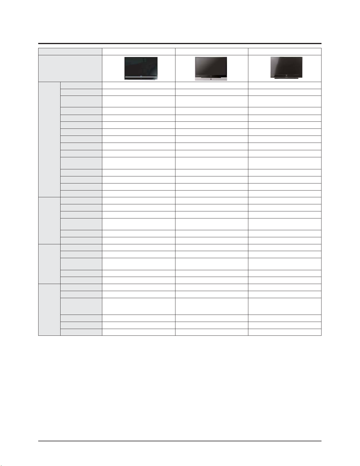
2-3 Specifications Analysis
Model HL-R5078W HL-R5668W HL-T6187S
Design
Picture
Display Device DLP DLP DLP
Built-in Tuner ATSC, NTSC ATSC, NTSC ATSC, NTSC
Display Format 1080p, 1080i, 720p, 480p, 480i 1080p, 1080i, 720p, 480p, 480i 1080p, 1080i, 720p, 480p, 480i
Screen Size 50 inch 56 inch 61 inch
Aspect ratio 16:9 16:9 16:9
Progressive scan Yes Yes Yes
Digital Comb Filter 3D Comb 3D Comb 3D Comb
First Surface Mirror Yes Yes Yes
Brightness
800cd/㎡ 600cd/㎡ 600cd/㎡
Contrast 10000:1 10000:1 10000:1
Color Wheel Size/Bearing
7segment/65¢,
Air Bearing
7segment/65¢,
Air Bearing
No Color Wheel
Anti-glare Sun Screen No No No
Screen Pitch 0.098mm 0.098mm 0.098mm
Image enhancer DNIe4 DNIe4 DNIe4
DMD xHD3 xHD3 xHD5
Audio
Base/Tremble/Balance No No No
Equalizer 5 Band 5 Band 5 Band
Auto Volume Leveler Yes Yes Yes
Surround Sound
TruSurround XT
Dolby Digital
TruSurround XT
Dolby Digital
TruSurround XT
Dolby Digital
Speaker system 2 Way 4 Speaker 2 Way 4 Speaker 2 Way 4 Speaker
Output Power 15Wx2 15Wx2 10Wx2
Features
2-Tuner Split-Screen PIP Yes(HD/SD/QAM) Yes(HD/SD/QAM) No
Split-screen Side-by-Side Yes Yes Yes
MTS with dbx Noise
Reduction/SAP
Yes Yes Yes
Still Picture Yes Yes Yes
Wise Link No No Yes
Connections
Plug & Play Yes Yes Yes
S-Video In Rear 2, Side1 Rear 2, Side1 Rear 2
HDTV Component
Video Input (Y, Pb, Pr)
1080p/1080i/480P/480i
Rear 2 Rear 2 Rear 2
PC Yes Yes Yes
HDMI Yes Yes Yes
Digital Sound Optical 1 Optical 1 Optical 1
Product Specification
2-6 Samsung Electronics
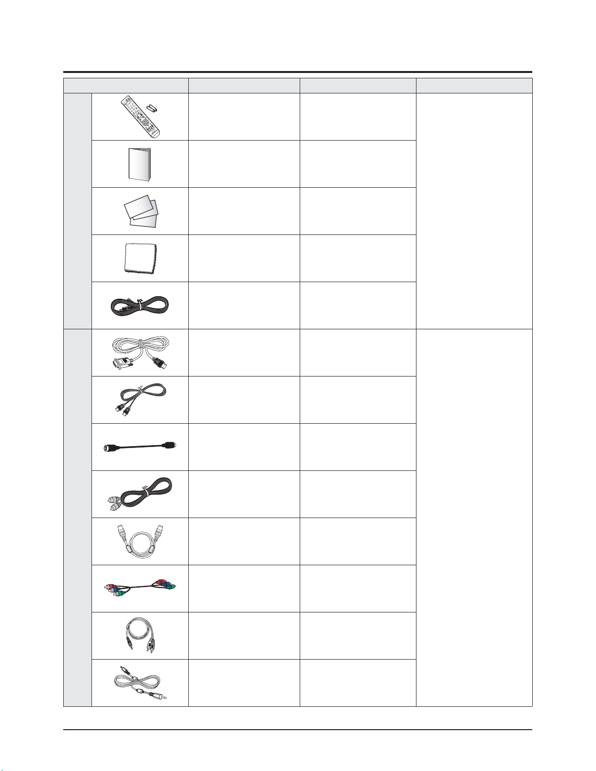
2-4 Accessories
Accessories Item Item code Remark
SuppliedAccessories
Remocon Control
Batteries
BP59-00125A
4301-000103
Samsung Service center
Owner's Manual BP68-00628A
Warranty Card/
Registration Card/
Safety Guide Manual/
Quick Guide Manual
AA68-00371C
AA68-03870B
AA68-03242F
-
Cloth-Clean BN63-01798A
Power Cord 3903-000144
Accessories that can be purchased
additionally
HDMI/DVI cable -
Electronics Store/
Internal shopping mall
HDMI/DVI cable -
HDMI Cable -
S-VIDEO Cable -
Antenna Cable -
Component Cables (RCA) -
1Stereo/2RCACable -
PC Audio Cable -

Product Specification
Samsung Electronics 2-7
Accessories Item Item code Remark
Audio/Video Cables -
Electronics Store/
Internal shopping mall

2-8 Samsung Electronics
MEMO

Alignment & Adjustment
Samsung Electronics 3-1
3. Alignment & Adjustment
3-1 Service Instruction
■ Check items listed after changing each
※ The Rear board is irremovable and supplied as a separate part in the field
1. Software version check :
After Entering the Service mode, Check the list below
* S/W Notation
"T_GALIAOS0_0001" indicates "Laurel Basic Model USA VER 0000".
2. Front Information Window check : See page 6-7.
3. DMD 0x00000001 indicates DMD board bit sequence program version.
4. Actuator Gain adjustment : See page 3-18.
5. Vertical / Horizontal Position adjustment : See page 3-15.
6. CCA : See page 3-16.
7. Board LED check : Check the LED is turned on.
(In the DMD Board)
8. Tilt/Focus adjustment : See page 3-20/21/22.
T_LAURAUS0_00XX
T-DLEDAUS5-3009
DMD 0x00000001
(DMD sequence ver)
DSP 0-0-0
(DMD DSP ver.)
RFS...
2007-01-17
T-LEEUM-0309
Check Items
Replaced Items
S/W Version Front LCD Actuator Gain
V-Position
H-Position
LED control Board LED Tilt Focus
Main Board
● ● ● ● ● ●
Rear Board
● ●
Main Power Board
●
Sub Power Board
●
Optical Engine
● ● ● ● ●
DMD Board
● ● ● ● ●
LED(R/G/B)
● ●
Front LED Assy
● ●
Detect Board
● ●
LED Driver board
● ●
Alignment & Adjustment
3-2 Samsung Electronics
3-2 How to Access Service Mode
1. Turn off the power to put the unit into the STAND-BY mode.
2. In order to enter the Service Mode, Press "Mute" → "1” → "8" → "2" → "POWER" button on the Remote Control.
In case entry into SERVICE MODE is unsuccessful, repeat the procedures above.
3. Initial DISPLAY State in times of Service Mode Switch overs
4. Buttons operations within Service Mode
OPTION CHECKSUM
DDP3021 SERVICE
CCA(ON)
DeSaturation(ON)
SP Actuator
CXD3815
MST33X9
SDP62(IPC)
SDP62(SCALER)
SDP62(PE)
S5H2200
KS1409_TUNER
STV82X8
CINEMA CCA
ESP
T-LAURAUS0-0020
T-DLEDAUS5-3009
DMD 0x00000001
DSP 0-0-0
RFS...
2007-00-00
T-LEEUM-0309
MENU Full Menu Display / Move to Parent Menu
Direction keys ▲ / ▼
Item Selection by Moving the Cursor
Direction keys ◀ / ▶
Data Increase/Decrease for the Selected Item
Source Cycles through the active input source that are connected to the unit
Enter Item Selection/execution
Alignment & Adjustment
Samsung Electronics 3-3
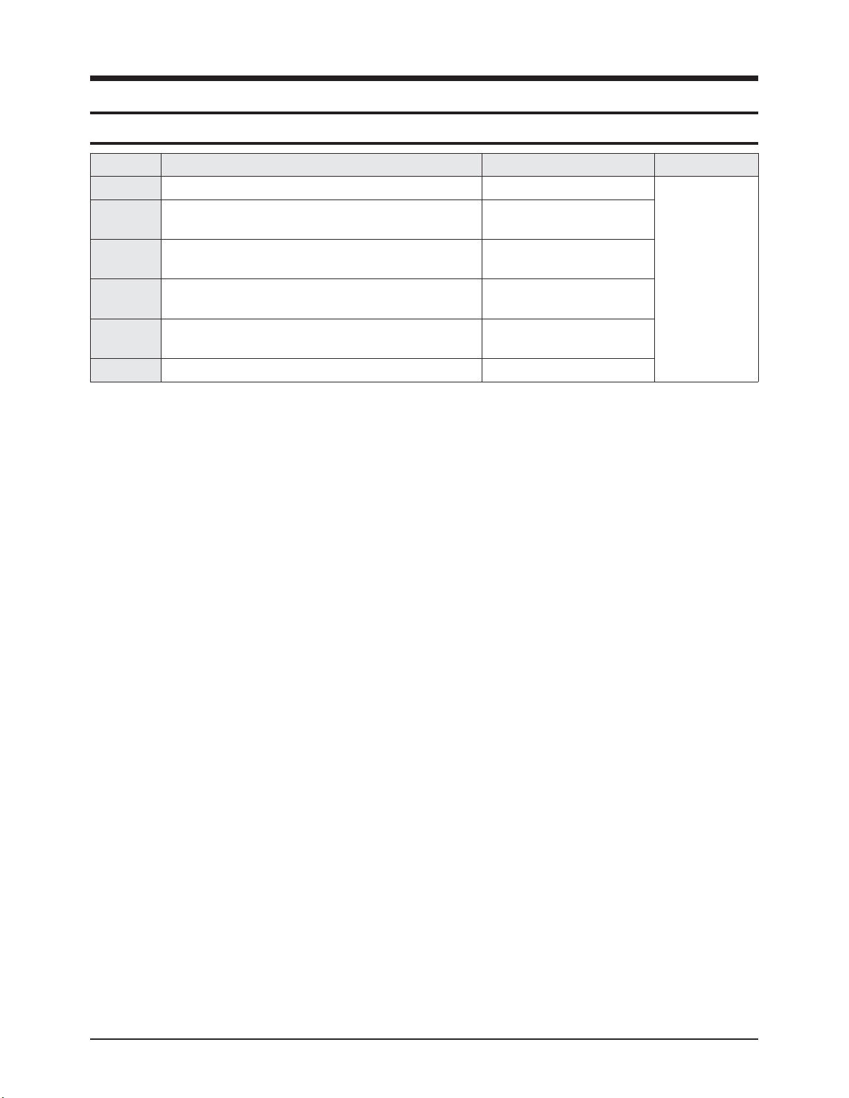
3-3 Factory Data
★ The underlined are items applied during the service adjustment. None of the others should be adjusted.
1. OPTION
No Item Range Default Remark
1 Factory Reset
2 WB Reset ON/OFF OFF Initialize the White Balance value
3 EER Reset - - Clear the EEPROM
4 User Reset - -
5
DIGITAL→DMD
- -
6 Led Clear - - Initialize lamp usage time. Lamp Life is set to zero
7 Lamp Life h Led on time counter
8 AUTO POWER ON/OFF 2
The sets turns on automatically when the power cord is
pluged
9 MUTE TIME(Video) 0~1000 440 Time which the screen will be black while switching
10 DDC Protection ON/OFF ON DDC write ON/OFF selection
11 LNA Default AUTO/OFF Auto LNA setting OFF/Auto selection
12 PROTECT ON/OFF ON Protection ON/OFF selection
13 WATCH DOG ON/OFF ON Watch Dog ON/OFF selection
14 WD COUNT 0 0 Count for Watch Dog event
15 DBG/RS232 SEL DEBUG/RS232 RS232 Rs232/Debug
16 BUS STOP ON/OFF OFF
17 FACTORY ON/OFF ON
18 SMART DEBUG ON/OFF OFF All user settings are set to default
19 EER COUNT ON/OFF ON/OFF OFF
20 EER COUNT 0x0000
21 LNA+ ON/OFF ON
22 LNA Check Count 10
23
DMD→DIGITAL
- - To trans the CCA data form DMD to DIGITAL
24 Shop Mode ON/OFF OFF
25 Color Gamut(Wide) ON
26 PC Ident AUTO/Enable AUTO
27 HotPlug on/off ON/OFF ON
28 HotPlug Off Hold Time 1500ms
29 HDMI Mute Time 0ms
30
DDP 3D Test 3D ready
Function TEST

Alignment & Adjustment
3-4 Samsung Electronics
2. DDP3021
No Item Range Default Remark
1 H/V-Position 0 ~ 60 H:60/V:30 Horizontal and Vertical image adjustment
2 V-FLIP Flip/Nomal Normal Vertical Flip Operation
3 H-FLIP Flip/Nomal Normal Horizontal Flip Operation
4 GAMMA 0 ~ 15 [4]OEM Gamma Table Selection
5 MPC ON/OFF OFF MPC Funcion On/Off
6 3D GLS_TRANS 1800
7 Calibration
8 Test Pattern (DDP) 0~18 0
This displays the built-in pattern of the DDP3021 chip.
DDP3021 drives the DMD panel, so displaying this pattern
means there is no error in the DDP3021 projection function
and the panel itself.
Alignment & Adjustment
Samsung Electronics 3-5
3. CCA(OFF)
No Item Range Default Remark
1 CCA CONTROL ON/OFF ON CCA On/Off Selection
2 Sensor Status NG_G_ Sensor valure
3 Red-x 0~32768 703 Red-x measurement value using CA210
4 Red-y 0~32768 292 Red-y measurement value using CA210
5 Red-Y 0~32768 80.0 Red-Y measurement value using CA210
6 Green-x 0~32768 173 Green-x measurement value using CA210
7 Green-y 0~32768 731 Green-y measurement value using CA210
8 Green-Y 0~32768 300.0 Green-Y measurement value using CA210
9 Blue-x 0~32768 146 Blue-xmeasurement value using CA210
10 Blue-y 0~32768 31 Blue-y measurement value using CA210
11 Blue-Y 0~32768 25.0 Blue-Y measurement value using CA210
12 ColorSensorSave Color Sensor valure save
13 WB Spread
14 [COOL2]DW_X 264
15 [COOL2]DW_Y 267
16 [COOL1]DW_X 269
17 [COOL1]DW_Y 274
18 [NORMAL]DW_X 276
19 [NORMAL]DW_Y 282
20 [WARM1]DW_X 285
21 [WARM1]DW_Y 293
22 [WARM2]DW_X 300
23 [WARM2]DW_Y 310
24 MaxCurrent RED 0
25 MaxCurrent GRN 0
26 MaxCurrent BLU 0
27 Sens RED 2604
28 Sens GRN 2244
29 Sens BLU 3238

Alignment & Adjustment
3-6 Samsung Electronics
No Item Range Default Remark
1 Desaturation Control ON
2 [NORMAL]Red-x 0~32768 660
3 [NORMAL]Red-y 0~32768 315
4 [NORMAL]Green-x 0~32768 260
5 [NORMAL]Green-y 0~32768 640
6 [NORMAL]Blue-x 0~32768 150
7 [NORMAL]Blue-y 0~32768 50
8 [NORMAL]Cyan-x 0~32768 179
9 [NORMAL]Cyan-x 0~32768 293
10 [NORMAL]Magenta-x 0~32768 263
11 [NORMAL]Magenta-y 0~32768 108
12 [NORMAL]Yellow-x 0~32768 412
13 [NORMAL]Yellow-y 0~32768 518
14 [WIDE]Red-x 0~32768 680
15 [WIDE]Red-y 0~32768 305
16 [WIDE]Green-x 0~32768 165
17 [\WIDE]Green-y 0~32768 700
18 [WIDE]Blue-x 0~32768 150
19 [WIDE]Blue-y 0~32768 38
20 [WIDE]Cyan-x 0~32768 163
21 [WIDE]Cyan-x 0~32768 293
22 [WIDE]Magenta-x 0~32768 265
23 [WIDE]Magenta-y 0~32768 95
24 [WIDE]Yellow-x 0~32768 413
25 [WIDE]Yellow-y 0~32768 520
26 [sRGB]Red-x 0~32768 640
27 [sRGB]Red-y 0~32768 330
28 [sRGB]Green-x 0~32768 295
29 [sRGB]Green-y 0~32768 595
30 [sRGB]Blue-x 0~32768 150
31 [sRGB]Blue-y 0~32768 60
32 [sRGB]Cyan-x 0~32768 225
33 [sRGB]Cyan-x 0~32768 390
34 [sRGB]Magenta-x 0~32768 365
35 [sRGB]Magenta-y 0~32768 170
36 [sRGB]Yellow-x 0~32768 422
37 [sRGB]Yellow-y 0~32768 494
38 Overlap 0%
39 DeSaturation Mode WIDE
4. DeSaturation(ON)

Alignment & Adjustment
Samsung Electronics 3-7
5. SP Actuator
No Item Range Default Remark
1 Actu Gain Control 0~175 40 Actuator Gain adjustment
2 Actu Gain Detail 0~175 40 Actuator Gain adjustment
3 Actu On/Off ON/OFF ON Actuator On/Off selection
4 DB On/Off ON/OFF ON
5 DB Border ON/OFF OFF
6 DB BP weight - 0%
7 DB Gain 0~3 0
8 DB Aperture 0~1 open
9 SB Gain 0~255 0
Alignment & Adjustment
3-8 Samsung Electronics
6. SDP62(IPC)
No Item Range Default Remark
1 (NR)M_NR_ON/OFF ON MAIN PICTURE NR ON/OFF
2 (NR)S_NR_ON/OFF ON SUB PICTURE NR ON/OFF
3
(NR)NR_Zeromotion_M 1
8 Gain contral for motion detection
4 (NR)NR_Fullmotion_M 240
5 (NR)M_MAX_WEIGHT 110 MAIN NR FRAME WEIGHT
6 (NR)S_MAX_WEIGHT 110 SUB NR FRAME WEIGHT
7 (NR)GMV_ON OFF Global Motion Vector ON/OFF
8 (NR)TH_FULLMD 64
9 51FLT_ON 3
10 FLT_SP ON
11 FLT_FP OFF
12 FLT_STL 0
13 FLT_MOT 0
14 Spatial_Analog_TH 0 0: Vertical Interpolation(do not use directional information)
15 Ticker_Mode All off Interlace only,Ecxept film,All on
16 Debuger_Mode off film,Stop,Motion,Moving,Judder,Ticker,Weigh
17 (FILM)3:2_Mode 1 3:2 PULL DWON MODE SELECTION
18 (FILM)2:2_Mode 1 2:2 PULL DWON MODE SELECTION
19 (FILM)FLM_32_22 3
20 CLK_OSD_PHASE 5 B1 OSD DATA LATCH PAHSE
21 (M)Test Pattern 0 INPUT TEST PATTERN
22 (S)Test Pattern 0

Alignment & Adjustment
Samsung Electronics 3-9
7. MST33X9
No Item Range Default Remark
1 RED CUTOFF 0~255 128
2 GREEN CUTOFF 0~255 128
3 BLUE CUTOFF 0~255 128
4 PHASE 0~64 0
5 RED GAIN 0~255 128
6 GREEN GAIN 0~255 128
7 BLUE GAIN 0~255 128
8 PLLDIV 0~4096 1687
9 PLLGAIN 0~31 22
10 CLPDLY 0~255 8
11 CLPDUR 0~255 32
12 HSOPW 0~255 96
13 SYNC_CTRL 0~255 64
14 SOGMID_CTRL 0~255 184
15 SEP_THR 0~255 32
16 PRECST 0~255 11
17 POSTCST 0~255 14
18 ADC_BWO 0~255 51
19 ADC_BW1 0~255 3
20 SOG_BW 0~255 238
21 Test Pattern(MST3369) 0~8 0

Alignment & Adjustment
3-10 Samsung Electronics
8. SDP62(SCALER)
No Item Range Default Remark
1 Main AUTO_PAGE_SE I2C ROM Filter Page Select
2 Main YH_PAGE 2 YH Filter Select
3 Main YV_PAGE 3 YV Filter Select
4 Main CH_PAGE 16 CH Filter Select
5 Main CV_PAGE 16 CV Filter Select
6 (CTI)GAINU 64 CB CTI gain
7 (CTI)GAINV 64 CR CTI gain
8 (CTI)R_CHCNT_ON ON
9 (MADE)SDR_MAX_TH 6 SDR STillFrame motion weight threshold
10 (MADE)SDR_MAX_TH 6 SDR STillFrame motion weight threshold
11 (MADE)ANTI_V OFF MADE IPC Motion V LPF ON/OFF
12 (MADE)ANTI_H ON MADE IPC Motion H LPF ON/OFF
13 MG_ON ON
14 MM_ON OFF
15 (MADE)DE_GAIN_X1 12 MADE Gain of horizontal high frequecy region
16 (MADE)DE_GAIN_X2 20 MADE Gain of horizontal middle frequecy region
17 (MADE)DE_GAIN_Y1 24 MADE Gain of vertical region
18 (MADE)DE_MR 6 LOG SCLAE GAIN
19 (MADE)H_RTH2 4
20 (MADE)CORING_ON/O ON MADE CORING ON/OFF
21 (MADE)H_CORING_F1 6 MADE CORING Threshold
22 (MADE)H_CORING_F2 6 MADE CORING Threshold
23 (MADE)V_CORING_F3 6 MADE CORING Threshold
24 (MADE)NE_ON OFF MADE linkage NE ON/OFF
25 (MADE)SUP_LIFT ON
26 (MADE)H_FILTER1 1 MAIN H FILER1 SELECT
27 (MADE)H_FILTER2 9 MAIN H FILER2 SELECT
28 (MADE)V_FILTER1 3 MAIN V FILER SELECT
29 DB_DEMO ON De-blocking Processing ON/OFF
30 PRE_DEMO OFF Pre-DE Processing ON/OFF
31 SP_DEMO ON Super Precision Processing ON/OFF
32 CTI_DEMO OFF CTI Processing ON/OFF
33 JR_SUB OFF
34 JR_DEMO OFF
Alignment & Adjustment
Samsung Electronics 3-11
9. SDP62(PE)
No Item Range Default Remark
1 Test Pattern 0 OUTPUT TEST PATTERN SELECTION
2 SNI_PROC_CEP ON Contrast Enhancement ON/OFF
3 SNI_PROC_DEP ON Detail Enhancement Processing ON/OFF
4 SNI_PROC_CEA ON Contrast Enhancement ON/OFF
5 SNI_PROC_CCS ON Color Compensation Processing ON/OFF
6 SNI_PROC_MCC ON MCC Processing ON/OFF
7 SNI_PROC_CA ON Contrast Adjustment Processing ON/OFF
8 SNI_PROC_CVD ON Color Vision Deficiency Processing ON/OFF
9 SNI_PROC_CVD ON Color Vision Deficiency Processing ON/OFF
10 SNI_BWS Adaptive BWS MODE SELECTION
11 B_RATIO 13000 Low lecel informatino for the minimum value
12 W_RATIO 6000 High lecel informatino for the minimum value
13 BLACK_TILT 110 Black Stretch Area
14 B_GAIN_MAX 380 Black slope gain limit
15 GAIN_X1 22 Gain of horizontal high frequecy region
16 GAIN_X2 25 Gain of horizontal middle frequecy region
17 GAIN_Y1 15 Gain of vertical high frequecy region
18 GAIN_Y2 19 Gain of vertical middle frequecy region
19 SUP_LIFE_SEL ON
20 BOOL_SUPP_SELX1 OFF Horizontal high frequecy Shoot Shppression ON/OFF
21 BOOL_SUPP_SELX2 OFF Horizontal middle frequecy Shoot Shppression ON/OFF
22 BOOL_SUPP_SELY1 ON Vertical high frequecy Shoot Shppression ON/OFF
23 BOOL_SUPP_SELY2 OFF Vertical middle frequecy Shoot Shppression ON/OFF
24 BOOL_ENH_SEL OFF Amplitude scaling block gain Processing ON/OFF
25 LOG_MODE ON Amplitude scaling block log scale ON/OFF
26 R_MR 150
27 CORING_ON ON Post Coring ON/OFF
28 RTH2 6 Noise Detection Block Threshold2
29 NDON OFF Noise Detection ON/OFF
30 WB_RED_C_COEFF 1024
31 WB_GRN_C_COEFF 1024
32 WB_BLU_C_COEFF 1024
33 WB_RED_B_COEFF 1024
34 WB_GRN_B_COEFF 1024
35 WB_BLU_B_COEFF 1024
36 R_Coring_TH1 2 Horizontal high frequecy Coring Threshold
37 R_Coring_TH2 2 Horizontal middle frequecy Coring Threshold
38 R_Coring_TH3 5 Vertical high frequecy Coring Threshold
39 R_Coring_TH4 5 Vertical middle frequecy Coring Threshold
Alignment & Adjustment
3-12 Samsung Electronics
No Item Range Default Remark
40 H_FILTER1 1 DE horizontal high frequecy Filter selection
41 H_FILTER2 8 DE horizontal middle frequecy Filter selection
42 V_FILTER1 1 DE vertical high frequecy Filter selection
43 V_FILTER2 2 DE vertical middle frequecy Filter selection
44 YSUBTRACT 64 Input Y channel Setup level
45 Sub Color 53 Color gain
46 Sub Color_Offset 0 N.C
47 DNIe On/Off ON DNIe Processing ON/OFF
48 Sub Contrast 106 Brightness adjustment for the high-light parts of the screen
49 Contrast Offset 5 Standard Contrast offset
50 (M)Contrast Offset 0 N.C
51 Sub Brightness 244 Brightness adjustment for the low-light parts of the screen
52 CRR 900 YCbCr TO RGB MATRIX
53 CBG 1780 YCbCr TO RGB MATRIX
54 CRG 1720 YCbCr TO RGB MATRIX
55 CBB 1023 YCbCr TO RGB MATRIX
56 CRR_MOVIE 750 MOVIE MODE YCbCr TO RGB MATRIX
57 CBG_MOVIE 1830 MOVIE MODE YCbCr TO RGB MATRIX
58 CRG_MOVIE 1670 MOVIE MODE YCbCr TO RGB MATRIX
59 CBB_MOVIE 1023 MOVIE MODE YCbCr TO RGB MATRIX
60 LGAIN 200 Contrast Adjustment dark gain
61 UGAIN 100 Contrast Adjustment bright gain
10. S5H2200
No Item Range Default Remark
1 Test Pattern(ALBA) 0~255 -
Loading...