


COLOR MONITOR
CKA4217L
CKA4227L
CKA5227L
SERVICEManual
COLOR MONITOR
1. Precautions
2. Product Specifications
3. Operating Instructions
4. Disassembly & Reassembly
5. Alignment & Adjustments
6. Troubleshooting
7. Exploded View & Parts
8. Block Diagram
9. Wiring Diagram
10. PCB Diagrams &
11. Schematic Diagrams

Samsung Electronics Co., Ltd. September 1997
Printed in Korea
Code No.: BH68-60933A

1 Precautions
Follow these safety, servicing and ESD precautions to prevent damage and to protect against potential hazards such as electrical shock and X-rays.
1-1 Safety Precautions
1-1-1 Warnings
1.For continued safety, do not attempt to modify the circuit board.
2.Disconnect the AC power before servicing.
3.When the chassis is operating, semiconductor heatsinks are potential shock hazards.
1-1-2 Servicing the High Voltage System and
CRT
WARNING: Empty or damaged E2PROM may cause excessive x-ray emissions.
Caution: When replacing the E2PROM, IC203 a high voltage step must be adjusted until high voltage becomes 24.5 kV. Standard dump from Softjig does this.
1.When servicing the high voltage system, remove the static charge by connecting a 10k ohm resistor in series with an insulated wire (such as a test probe) between the chassis and the anode lead. (Disconnect the AC line cord from the AC outlet.)
2.High Voltage Adjustment
This monitor does not need to adjust high voltage, standard dump from Softjig automatically adjust the high voltage to 24.5kV.
3.It is essential that service technicians have an accurate high voltage meter available at all times. Check the calibration of this meter periodically.
4.When troubleshooting a monitor with excessively high voltage, avoid being unnecessarily close to the monitor. Do not operate the monitor for longer than is necessary to locate the cause of excessive voltage.
5.High voltage should always be kept at the rated value, no higher. Be sure all service personnel are aware of the procedures and instructions covering X-rays.
The only potential source of X-ray in current solid state display monitors is the tube. However, the CRT does not emit measurable X-ray radiation if the high voltage is at the high voltage adjustment value.
Only when high voltage is excessive are X-rays capable of penetrating the shell of the CRT, including the lead in glass material. Operation at high voltages may also cause failure of the CRT or high voltage circuitry.
6.When the high voltage regulator is operating properly, there is no possibility of an X-ray problem. Test the brightness and use a meter to monitor the high voltage each time a color monitor comes in for service. Make sure the high voltage does not exceed its specified value and that it is regulating correctly.
7.The CRT is especially designed to prohibit X-ray emissions. To ensure continued X-ray protection, replace the CRT with only one that is the same or equivalent type as the original. Carefully reinstall the CRT shields and mounting hardware; these also provide X-ray protection.
8.Handle the CRT only when wearing shatterproof goggles and after completely discharging the high voltage anode.
9.Do not lift the CRT by the neck.
CKA42*7L/5227L |
1-1 |
1 Precautions
1-1-3 Fire and Shock Hazard
Before returning the monitor to the user, perform the following safety checks:
1.Inspect each lead dress to make certain that the leads are not pinched or that hardware is not lodged between the chassis and other metal parts in the monitor.
2.Inspect all protective devices such as nonmetallic control knobs, insulating materials, cabinet backs, adjustment and compartment covers or shields, isolation resistor-capacitor networks, mechanical insulators, etc.
|
(READING SHOULD |
|
NOT BE ABOVE 0.5mA) |
|
LEAKAGE |
DEVICE |
CURRENT |
UNDER |
TESTER |
TEST |
|
|
TEST ALL |
|
EXPOSED METAL |
|
SURFACES |
2-WIRE CORD |
|
ALSO TEST WITH |
|
PLUG REVERSED |
|
(USING AC ADAPTER |
|
PLUG AS REQUIRED) |
|
|
EARTH |
|
GROUND |
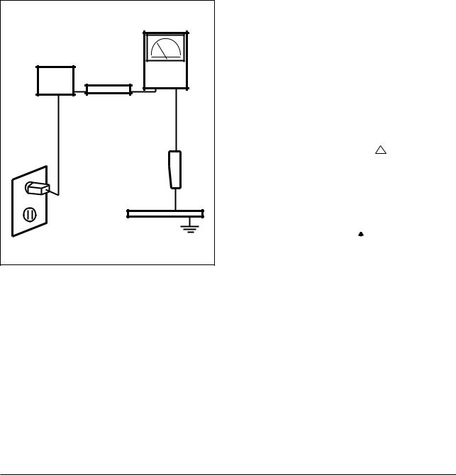
Figure1-1. Leakage Current Test Circuit
3.Leakage Current Hot Check (Figure 1-1):
WARNING: Do not use an isolation transformer during this test.
Use a leakage current tester or a metering system that complies with American National Standards Institute (ANSI C101.1, Leakage Current for Appliances), and Underwriters Laboratories (UL Publication UL1410, 59.7).
4.With the unit completely reassembled, plug the AC line cord directly into a 120V AC outlet. With the unit’s AC switch first in the ON position and then OFF, measure the current between a known earth ground (metal water pipe, conduit, etc.) and all exposed metal parts, including: metal cabinets, screwheads and control shafts. The current measured should not exceed 0.5 milliamp. Reverse the power-plug prongs in the AC outlet and repeat the test.
1-1-4 Product Safety Notices
Some electrical and mechanical parts have special safety-related characteristics which are often not evident from visual inspection. The protection they give may not be obtained by replacing them with components rated for higher voltage, wattage, etc. Parts that have special safety characteristics are identified by ! on schmatics and parts lists. Asubstitute replacement that does not have the same safety characteristics as the recommended replacement part might create shock, fire and / or other hazards. Product safety is under review continuously and new instructions are issued whenever appropriate.
Components identified by  on schematics and parts lists must be sealed by a soldering iron after replacement and adjustment.
1-2 |
CKA42*7L/5227L |

1 Precautions
1-2 Servicing Precautions
WARNINGS: An electrolytic capacitor installed with the wrong polarity might explode.
Cautions: Before servicing units covered by this service manual, read and follow the Safety Precautions section of this manual.
When replacing the E2PROM, high voltage step must be adjusted until high voltage becomes 24.5 kV. Standard dump from Softjig does this.
Note: If unforeseen circumstances create conflict between the following servicing precautions and any of the safety precautions, always follow the safety precautions.
1-2-1 General Servicing Precautions
1.Servicing precautions are printed on the cabinet, and should be followed closely.
2.Always unplug the unit’s AC power cord from the AC power source before attempting to:
(a) remove or reinstall any component or assembly, (b) disconnect PCB plugs or connectors, (c) connect a test component in parallel with an electrolytic capacitor.
3.Some components are raised above the printed circuit board for safety. An insulation tube or tape is sometimes used. The internal wiring is sometimes clamped to prevent contact with thermally hot components. Reinstall all such elements to their original position.
4.After servicing, always check that the screws, components and wiring have been correctly reinstalled. Make sure that the area around the serviced part has not been damaged.
5.Check the insulation between the blades of the AC plug and accessible conductive parts (examples: metal panels, input terminals and earphone jacks).
6.Insulation Checking Procedure: Disconnect the power cord from the AC source and turn the power switch ON. Connect an insulation resistance meter (500 V) to the blades of the AC plug.
The insulation resistance between each blade of the AC plug and accessible conductive parts (see above) should be greater than 1 megohm.
7.Never defeat any of the +B voltage interlocks. Do not apply AC power to the unit (or any of its assemblies) unless all solid-state heat sinks are correctly installed.
8.Always connect a test instrument’s ground lead to the instrument chassis ground before connecting the positive lead; always remove the instrument’s ground lead last.
CKA42*7L/5227L |
1-3 |

1 Precautions
1-3 Electrostatically Sensitive Devices (ESD) Precautions
Some semiconductor (solid state) devices can be easily damaged by static electricity. Such components are commonly called Electrostatically Sensitive Devices (ESD). Examples of typical ESD devices are integrated circuits and some field-effect transistors. The following techniques will reduce the incidence of component damage caused by static electricity.
1.Immediately before handling any semiconductor components or assemblies, drain the electrostatic charge from your body by touching a known earth ground. Alternatively, wear a discharging wrist-strap device. To avoid a shock hazard, be sure to remove the wrist strap before applying power to the monitor.
2.After removing an ESD-equipped assembly, place it on a conductive surface such as aluminum foil to prevent accumulation of an electrostatic charge.
3.Do not use freon-propelled chemicals. These can generate electrical charges sufficient to damage ESDs.
4.Use only a grounded-tip soldering iron to solder or desolder ESDs.
5.Use only an anti-static solder removal device. Some solder removal devices not classified as “anti-static” can generate electrical charges sufficient to damage ESDs.
6.Do not remove a replacement ESD from its protective package until you are ready to install it. Most replacement ESDs are packaged with leads that are electrically shorted together by conductive foam, aluminum foil or other conductive materials.
7.Immediately before removing the protective material from the leads of a replacement ESD, touch the protective material to the chassis or circuit assembly into which the device will be installed.
Caution: Be sure no power is applied to the chassis or circuit and observe all other safety precautions.
8.Minimize body motions when handling unpackaged replacement ESDs. Motions such as brushing clothes together, or lifting your foot from a carpeted floor can generate enough static electricity to damage an ESD.
9. Indicates ESDs on the Schematic Diagram in this manual.
1-4 |
CKA42*7L/5227L |

2 Product Specifications
2-1 Specifications
Item |
|
|
|
|
Description |
|
|
|
|
||||
Picture Tube: |
CKA42*7L: 14-Inch (36 cm); 13.2-Inch (33.5 cm) viewable, 90° Deflection, |
|||||
|
CKA5227L: 15-Inch (38 cm); 13.8-Inch (35 cm) viewable, flat-face tube, 90° Deflection, |
|||||
|
0.28 mm Dot pitch, Semi-tint, Non-glare, Antistatic silica coating, Invar shadow mask |
|||||
|
|
|
|
|
||
Scanning Frequency |
Horizontal |
: |
30 kHz to 55 kHz (Automatic) |
|
||
|
Vertical |
: |
50 Hz to 120 Hz (Automatic) |
|
||
|
|
|
|
|
||
Display Colors |
Unlimited colors |
|
|
|
||
|
|
|
|
|
|
|
Maximum Resolution |
Horizontal |
: |
1024 Dots |
|
|
|
|
Vertical |
: |
768 Lines |
|
|
|
|
|
|
||||
Input Video Signal |
Analog, 0.714 Vp-p positive at 75 Ω , internally terminated |
|||||
|
|
|
||||
Input Sync Signal |
Separate Sync : TTL level positive/negative |
|
||||
|
|
|
|
|
|
|
Maximum Pixel Clock |
65 MHz |
|
|
|
|
|
|
|
|
|
|
|
|
Active Display |
|
|
CKA42*7L |
|
CKA5227L |
|
|
|
|
||||
Horizontal |
255 mm ± 3 mm (4:3 ratio) |
267 mm ± 3 mm (4:3 ratio) |
||||
Vertical |
191 mm ± 3 mm |
|
|
200 mm ± 3 mm |
||
|
|
|
||||
Input Voltage |
AC 90 to 264 Volts, 60 Hz/50 Hz ± 3 Hz |
|
||||
|
|
|
|
|
||
Power Consumption |
73 Watt (max) |
|
|
|
||
|
|
|
|
|
|
|
Dimensions |
|
|
CKA42*7L |
|
CKA5227L |
|
|
|
|
||||
Unit (W x D x H) |
13.7 x 15.2 x 14.3 Inches (348 x 385 x 362.5 mm) |
14.6 x 15.6 x 14.8 Inches (370 x 395 x 377 mm) |
||||
Carton (W x D x H) |
16.6 x 18.1 x 15.4 Inches (422 x 460 x 390 mm) |
17.9 x 19.6 x 17.0 Inches (454 x 497 x 433 mm) |
||||
|
|
|
|
|
||
Weight (Net/Gross) |
CKA42*7L : |
|
23.1 lbs (10.5 kg) / 27.3 lbs (12.4 kg) |
|||
|
CKA5227L : |
|
27.6 lbs (12.5 kg) / 30.9 lbs (14.0 kg) |
|||
|
|
|
|
|
||
Environmental Considerations |
Operating Temperature |
: |
32°F to 104°F (0°C to 40°C) |
|||
|
|
|
|
|
Humidity : 10 % to 80 % |
|
|
Storage Temperature |
: |
-4°F to 113°F (-20°C to 45°C) |
|||
|
|
|
|
|
Humidity : 5 % to 95 % |
|
|
|
|
|
|
|
|
CRT Code No. |
|
|
|
|
|
|
|
|
|
||||
• CKA42*7L/5227L complies with SWEDAC (MPR II) recommendations for reduced electromagnetic fields. |
||||||
• Designs and specifications are subject to change without prior notice. |
|
|||||
|
|
|
|
|
|
|
CKA42*7L/5227L |
2-1 |
2 Product Specifications
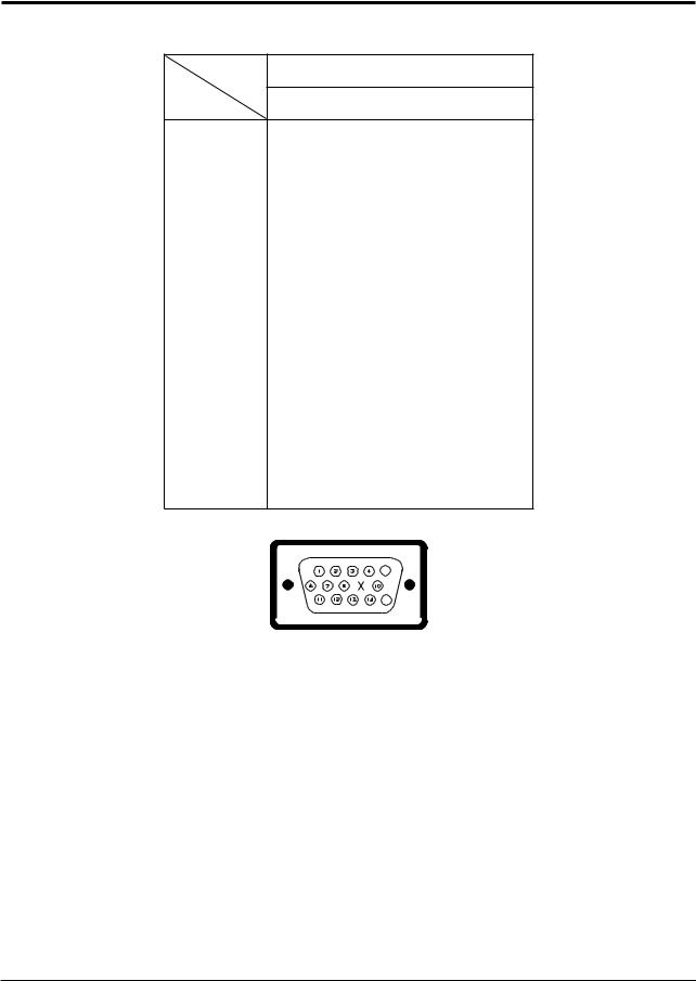
2-2 Pin Assignments
Sync |
15-Pin Signal Cable Connector (Figure 2-1) |
Type |
|
Pin No. |
Separate |
|
|
1 |
Red |
2 |
Green |
3 |
Blue |
4 |
GND |
5 |
DDC Return |
6 |
GND-R |
7 |
GND-G |
8 |
GND-B |
9 |
Reserved |
10 |
GND-Sync/Self-raster |
11 |
GND |
12 |
DDC Data |
13 |
H-Sync |
14 |
V-Sync |
15 |
DDC Clock |
|
5 |
|
15 |
Figure 2-1. Male Type
2-2 |
CKA42*7L/5227L |

2 Product Specifications
2-3 Timing Chart
This section of the service manual describes the timing that the computer industry recognizes as standard for computer-generated video signals.
Table 2-1. Timing Chart
Mode |
|
IBM |
|
|
VESA |
|
|
|
720/70 Hz |
640/60 Hz |
640/75 Hz |
640/85 Hz |
800/75 Hz |
800/85 Hz |
1024/60 Hz |
Timing |
720 x 400 |
640 x 480 |
640 x 480 |
640 x 480 |
800 x 600 |
800 x 600 |
1024 x 768 |
|
|
|
|
|
|
|
|
fH (kHz) |
31.469 |
31.469 |
37.500 |
43.269 |
46.875 |
53.674 |
48.363 |
A µsec |
31.777 |
31.778 |
26.667 |
23.111 |
21.333 |
18.631 |
20.677 |
B µsec |
3.813 |
3.813 |
2.032 |
1.556 |
1.616 |
1.138 |
2.092 |
C µsec |
1.907 |
1.907 |
3.810 |
2.222 |
3.232 |
2.702 |
2.462 |
D µsec |
25.422 |
25.422 |
20.317 |
17.778 |
16.162 |
14.222 |
15.754 |
E µsec |
0.636 |
0.636 |
0.508 |
1.556 |
0.323 |
0.569 |
0.369 |
fV (Hz) |
70.087 |
59.940 |
75.000 |
85.008 |
75.000 |
85.061 |
60.004 |
O msec |
14.268 |
16.683 |
13.333 |
11.764 |
13.333 |
11.756 |
16.666 |
P msec |
0.064 |
0.064 |
0.080 |
0.069 |
0.064 |
0.056 |
0.124 |
Q msec |
1.080 |
1.048 |
0.427 |
0.578 |
0.448 |
0.503 |
0.600 |
R msec |
12.711 |
15.253 |
12.800 |
11.093 |
12.800 |
11.179 |
15.880 |
S msec |
0.413 |
0.318 |
0.027 |
0.023 |
0.021 |
0.019 |
0.062 |
Clock |
|
|
|
|
|
|
|
Frequency |
28.322 |
25.175 |
31.500 |
36.000 |
49.500 |
56.250 |
65.000 |
(MHz) |
|
|
|
|
|
|
|
Polarity |
|
|
|
|
|
|
|
H.Sync |
Negative |
Negative |
Negative |
Negative |
Positive |
Positive |
Negative |
V.Sync |
Positive |
Negative |
Negative |
Negative |
Positive |
Positive |
Negative |
Remark |
Separate |
Separate |
Separate |
Separate |
Separate |
Separate |
Separate |
|
|
|
Separate Sync |
|
|
|
Horizontal |
|
|
|
Vertical |
|
|
Video |
|
|
|
Video |
|
|
C C |
DD |
E |
E |
Q Q |
R R |
S S |
Sync |
|
|
|
Sync |
|
|
|
B |
|
|
|
P |
|
|
B |
|
|
|
P |
|
|
A A |
|
|
|
O O |
|
|
H/V Composite Sync |
|
|
|
|
VIDEO |
|
A |
Q |
R |
S |
Horizontal |
Vertical |
|
|
|
P |
O |
|
B |
|
|
|
|
|
|
|
A : Line time total |
B : Horizontal sync width |
O : Frame time total |
P : Vertical sync width |
C : Back porch |
D : Active time |
Q : Back porch |
R : Active time |
E : Front porch |
|
S : Front porch |
|
|
|
|
|
|
|
|
|
CKA42*7L/5227L |
2-3 |

2 Product Specifications
Memo
2-4 |
CKA42*7L/5227L |

3 Operating Instructions
3-1 Front View and Controls
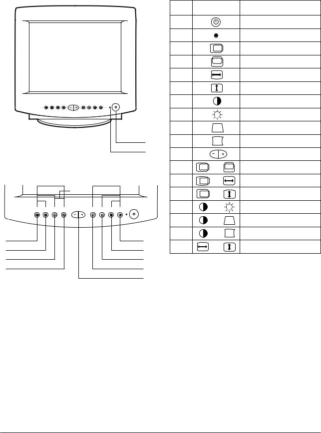
3-1-1 CKA4227L Front View
1
2
12 |
13 |
14 |
17 |
16 |
15 |
3 |
|
|
|
|
7 |
4 |
|
|
|
|
8 |
5 |
|
|
|
|
9 |
6 |
|
|
|
|
10 |
|
|
|
|
|
11 |
Figure 3-1. Front Control Panel
Table 3-1. Front Panel Controls
Location |
Symbol |
Description |
1 |
|
Power Button |
|
|
Power Indicator LED (Dual Color) |
3 |
|
Horizontal Position Button |
4 |
|
Vertical Position Button |
5 |
|
Horizontal Size Button |
6 |
|
Vertical Size Button |
7 |
|
Contrast Control |
8 |
|
Brightness Control |
9 |
|
Trapezoid Button |
10 |
|
Side Pincushion Button |
11 |
|
Adjustment Buttons |
12 |
+ |
Parallelogram |
13 |
+ |
V-Linearity |
14 |
+ |
Pinbalance Button |
15 |
+ |
Degauss |
16 |
+ |
Recall |
17 |
+ |
User Delete |
CKA42*7L/5227L |
3-1 |
3 Operating Instructions
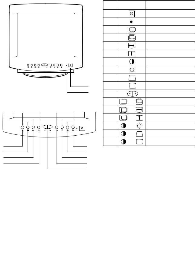
3-1-2 CKA5227L Front View
1
2
|
|
|
18 |
|
|
12 |
13 |
14 |
17 |
16 |
15 |
3 |
|
|
|
|
7 |
4 |
|
|
|
|
8 |
5 |
|
|
|
|
9 |
6 |
|
|
|
|
10 |
|
|
|
|
|
11 |
Figure 3-2. Front Control Panel
Table 3-2. Front Panel Controls
Location |
Symbol |
Description |
1 |
|
Power Button |
|
|
Power Indicator LED (Dual Color) |
3 |
|
Horizontal Position Button |
4 |
|
Vertical Position Button |
5 |
|
Horizontal Size Button |
6 |
|
Vertical Size Button |
7 |
|
Contrast Control |
8 |
|
Brightness Control |
9 |
|
Trapezoid Button |
10 |
|
Side Pincushion Button |
11 |
|
Adjustment Buttons |
12 |
+ |
Parallelogram |
13 |
+ |
V-Linearity |
14 |
+ |
Pinbalance Button |
15 |
+ |
Degauss |
16 |
+ |
Recall |
17 |
+ |
User Delete |
18 |
+ |
Tilt (Optional) |
3-2 |
CKA42*7L/5227L |
3-1-3 CKA4217L Front View
1
2
12 |
13 |
14 |
17 |
16 |
15 |
3 |
|
|
|
|
7 |
4 |
|
|
|
|
8 |
5 |
|
|
|
|
9 |
6 |
|
|
|
|
10 |
|
|
|
|
|
11 |
Figure 3-3. Front Control Panel
3 Operating Instructions
Table 3-3. Front Panel Controls
Location |
Symbol |
Description |
1 |
|
Power Button |
|
|
Power Indicator LED (Dual Color) |
3 |
|
Horizontal Position Button |
4 |
|
Vertical Position Button |
5 |
|
Horizontal Size Button |
6 |
|
Vertical Size Button |
7 |
|
Contrast Control |
8 |
|
Brightness Control |
9 |
|
Trapezoid Button |
10 |
|
Side Pincushion Button |
11 |
|
Adjustment Buttons |
12 |
+ |
Parallelogram |
13 |
+ |
V-Linearity |
14 |
+ |
Pinbalance Button |
15 |
+ |
Degauss |
16 |
+ |
Recall |
17 |
+ |
User Delete |
CKA42*7L/5227L |
3-3 |
3 Operating Instructions
Note 1: When used with a computer equipped with VESA DPMS functions, this monitor is EPA Energy Star compliant and NUTEK compliant.
Table 3-4. Display Power Management Signaling (DPMS); CKA42*7L
State |
Normal |
Power saving function EPA/NUTEK |
|||
|
|
|
|
||
Items |
Operation |
Stand-By |
Suspend Mode |
Power Off Mode |
|
|
Mode |
Position A |
Position B |
||
|
|
|
|
|
|
Horizontal Sync |
Active |
Inactive |
Active |
Inactive |
|
Vertical Sync |
Active |
Active |
Inactive |
Inactive |
|
Video |
Active |
Blanked |
Blanked |
Blanked |
|
|
|
|
|
|
|
Power |
|
Green |
Green |
Green |
|
Green |
Blinking (0.5 |
Blinking (1 |
Blinking (1 sec |
||
Indicator |
|||||
|
sec interval) |
sec interval) |
interval) |
||
|
|
||||
Power |
73 W (max.) |
50 W |
Less than |
Less than |
|
55 W |
|||||
Consumption/hr |
(nominal) |
15 W |
5 W |
||
(nominal) |
|||||
|
|
|
|
||
Table 3-5. Display Power Management Signaling (DPMS); CKA5227L
State |
Normal |
Power saving function EPA/NUTEK |
|||
|
|
|
|
||
Items |
Operation |
Stand-By |
Suspend Mode |
Power Off Mode |
|
|
Mode |
Position A |
Position B |
||
|
|
|
|
|
|
Horizontal Sync |
Active |
Inactive |
Active |
Inactive |
|
Vertical Sync |
Active |
Active |
Inactive |
Inactive |
|
Video |
Active |
Blanked |
Blanked |
Blanked |
|
|
|
|
|
|
|
Power |
|
Green |
Green |
Green |
|
Green |
Blinking (0.5 |
Blinking (1 |
Blinking (1 sec |
||
Indicator |
|||||
|
sec interval) |
sec interval) |
interval) |
||
|
|
||||
Power |
73 W (max.) |
50 W |
Less than |
Less than |
|
60 W |
|||||
Consumption/hr |
(nominal) |
15 W |
5 W |
||
(nominal) |
|||||
|
|
|
|
||
3-4 |
CKA42*7L/5227L |

4 Disassembly and Reassembly
This section of the service manual describes the disassembly and reassembly procedures for the CKA42*7L/5227L monitors.
WARNING: This monitor contains electrostatically sensitive devices. Use caution when handling these components.
4-1 Disassembly
Cautions:1. Disconnect the monitor from the power source before disassembly.
2. Follow these directions carefully; never use metal instruments to pry apart the cabinet.
4-1-1 Cabinet Disassembly
1.With a pad beneath it, stand the monitor on its front with the screen facing downward and the base closest to you. Make sure nothing will damage the screen.
2.Press in the tab on the Cabinet Bottom and pull the Tilt and Swivel Base upward to remove it.
3.Working from the back of the monitor, remove the four screws and remove the Rear Cover.
4.Using pinch-nose pliers or long-nose pliers, carefully disconnect the Anode Cap from the CRT.
Caution: Do not touch the anode contact on the CRT.
4-1-2 Removing the CRT Socket PCB
1.Complete all previous steps.
2.Disconnect CRT and Main PCB ground wires on CRT Socket PCB and Shield Cover.
3.Desolder the 5 tabs on the underside of the CRT Socket PCB shield and remove the CRT Socket PCB Shield.
4.Using a knife, cut through the silicone bond and lift off the CRT Socket PCB.
5.Disconnect connectors CN102 and two ground wires on the CRT Socket PCB.
4-1-3 Removing the Main PCB
1.Complete all previous steps.
2.Disconnect Degaussing Coil at the CN601 connector on the Main PCB.
3.Disconnect all easily accessible ground wires on the Main PCB and Chassis Bottom.
4.Disconnect the DY connector between the DY and the CN301, CN302, CN502 and CN503 connector on the Main PCB.
5.Remove the screws on the back and along each side of the Chassis Bottom.
6.Carefully lift the Main PCB Ass’y.
7.Remove all other ground wires.
4-1-4 CRT Ass’y Disassembly
1.Complete all previous steps.
2.Straighten the Degaussing Coil Assembly coated metal ties and lift Coil Ass’y from the CRT.
3.Remove the four corner screws and lift the CRT up and away from the Front Cover Assembly and place it on a padded surface.
Caution: Do not lift the CRT by the neck.
If you will be returning this CRT to the monitor, be sure to place the CRT face downward on a protective pad.
CKA42*7L/5227L |
4-1 |

4 Disassembly and Reassembly
4-2 Reassembly
With the CRT facing downward on a protective pad, use the steps that follow to reassemble the monitor.
4-2-1 Replacing the CRT
1.Loop the CRT Ground Ass’y around the back of the CRT and under the four corner metal ears. Position last the corner with the spring.
2.With the Front Cover Assembly lying face down on a protective pad, position the CRT so that the corner metal ears fit properly in the Front Cover Assembly.
3.Secure the CRT ground Ass’y and CRT at each of the four corners with the CRT screws.
4.Replace the Degaussing Coil Assembly and wrap the Coil with the plastic coated metal ties to hold the Coil in place.
4-2-3 Replacing the CRT Socket PCB
1.Lock the Focus (G3) wire on the CRT Socket and reconnect the Screen (G2) wire on the CRT Socket PCB.
2.Reconnect the CRT Socket on the CRT pins and apply silicon bond at the Plug/Socket Junction.
3.Replace the CRT and Main PCB ground wires on CRT Socket PCB and Shield Cover.
4.Reconnect the connectors CN102 to the CRT Socket PCB.
5.Solder the 5 tabs on the underside of the CRT Socket Shield.
4-2-2 Replacing the Main PCB
1.Stand the monitor on its front with the screen facing downward.
2.Slide the Main PCB into the Chassis Bottom and replace the wires and screws on the Chassis Bottom.
3.Position the Main PCB Ass’y in the front Cabinet and secure it with the screws.
4.Replace both side CRT ground wires on the Chassis Bottom.
5.Replace the Degaussing Coil at the CN601 connector on the Main PCB.
6.Replace the DY connector at the CN301, CN302, CN502 and CN503 connector on the Main PCB.
7.Replace all easily accessible ground wires on the Main PCB and Chassis Bottom.
8.Replace the Anode Cap.
4-2-4 Cabinet Reassembly
1.Complete all previous steps.
2.Position the Rear Cover marking sure the tabs along the front edge are properly snapped in place. Replace the four screws.
3.Snap the Tilt and Swivel Base into position.
4.Set the monitor on its Base and make sure that the CRT faceplate was not scratched or otherwise damaged.
4-2 |
CKA42*7L/5227L |

5 Alignment and Adjustments
This section of the service manual explains how to make permanent adjustments to the monitor. Directions are given for adjustments using the monitor Interface Board Ver. 2.0 and software (SoftJig).
5-1 Adjustment Conditions
Caution: Changes made without the SoftJig are saved only to the user mode settings. As such, the settings are not permanently stored and may be inadvertently deleted by the user.
5-1-1 Before Making Adjustments
5-1-1 (a) ORIENTATION
When servicing, always face the monitor to the east.
5-1-1 (b) MAGNETIC FIELDS
Whenever possible, use magnetic field isolation equipment such as a Helmholtz field to surround the monitor. If a Helmholtz field is not available, frequently degauss the unit under test.
5-1-1 (f) +B 13 V LINE CHECK
No beam
Contrast: Maximum
Brightness: Maximum
Check the DC 13 V ± 0.2 V at Cathode of D616 Point and GND.
5-1-1 (g) HIGH VOLTAGE CHECK
No beam
Contrast: Maximum
Brightness: Maximum
Caution: Other electrical equipment may cause external magnetic fields which may interfere with monitor performance.
Use an external degaussing coil to limit magnetic build up on the monitor. If an external degaussing coil is not available, use the internal degaussing circuit. However, do not use the internal degaussing circuit more than once per 30 minutes.
5-1-1 (c) WARM-UP TIME
The monitor must be on for 30 minutes before starting alignment procedures. Warm-up time is especially critical in Color Temperature and White Balance adjustments.
5-1-1 (d) SIGNAL
Analog, 0.714 Vp-p positive at 75 ohm, internal termination
Sync: Separate
(TTL level negative/positive)
5-1-1 (e) SCANNING FREQUENCY
Check the high voltage to 24.5 ± 0.5 kV at anode and GND.
5-1-1 (i) CENTER RASTER
Adjust SW401 so that the back raster comes to the center when you apply a signal of 53.7 kHz/
85 Hz.
5-1-1 (j) BRIGHTNESS AND CONTRAST
Unless otherwise specified, adjust brightness and contrast buttons:
Brightness: Maximum
(press button until the LED is blink)
Contrast: Maximum
(press button until the LED is blink)
Horizontal: |
30 kHz to 55 kHz (automatic) |
Vertical: |
50 Hz to 120 Hz (automatic) |
Unless otherwise specified, adjust at the 800 x 600 mode (H : 53.7 kHz, V: 85 Hz) signals.
Refer to Table on page 2-5.
CKA42*7L/5227L |
5-1 |

5 Alignment and Adjustments
5-1-2 Required Equipment
The following equipment may be necessary for adjustment procedures:
5-1-2 (a) DISPLAY CONTROL ADJUSTMENT
1.Non-metallic (–) screwdriver: 1.5 mm Non-metallic (–) screwdriver: 3 mm
2.Philips (+) screwdriver: 1.5 mm
3.Non-metallic hexkey: 2.5 mm
4.Digital Multimeter (DMM), or Digital Voltmeter (DVM)
5.Signal generator, or
Computer with a video board that uses the ET-4000 chipset (strongly recommended if using Samsung DM 200 software) and that displays: 800 x 600 @ 85 Hz, or 800 x 600 @ 75 Hz (minimum).
6.Personal computer
7.Required software: Softjig.exe from Samsung, Samsung DM200, or DisplayMate for Windows from Sonera Technologies
8.Interface Board Ver. 2.0 Code No. BH81-90001K
9.Parallel communications cable (25-pin to 25-pin); Code No. BH81-90001H
10.Signal cable (15-pin to 15-pin cable with additional 3-pin connector); Code No. BH81-90001J
11.5 V DC adapter, not supplied
Note: SoftJig Assembly (includes items 8, 9 and 10 Code No. BH81-90001L
5.1-2 (b) COLOR ADJUSTMENTS
1.All equipment listed in 5-1-2 (a), above
2.Color analyzer, or any luminance measurement equipment
5-2 |
CKA42*7L/5227L |
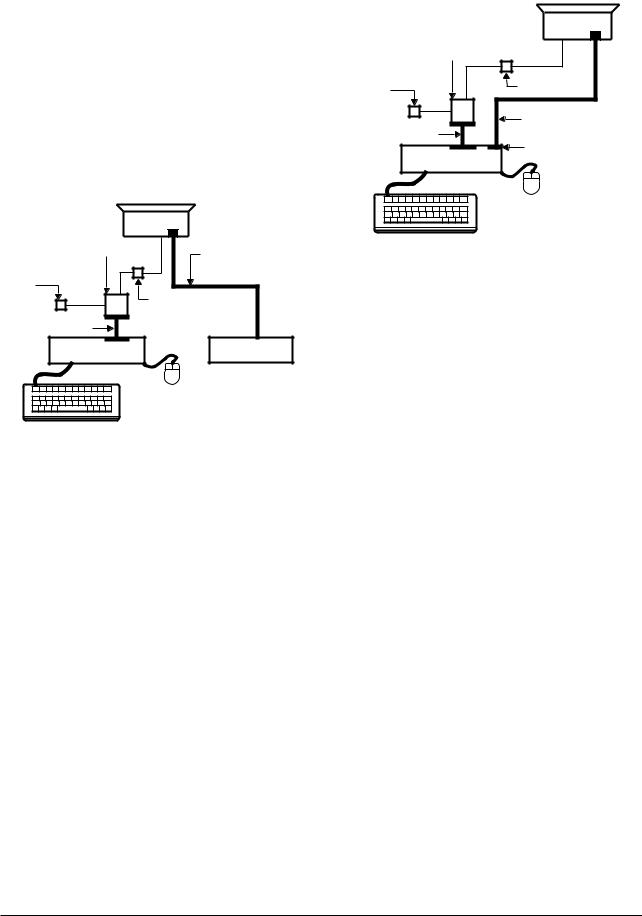
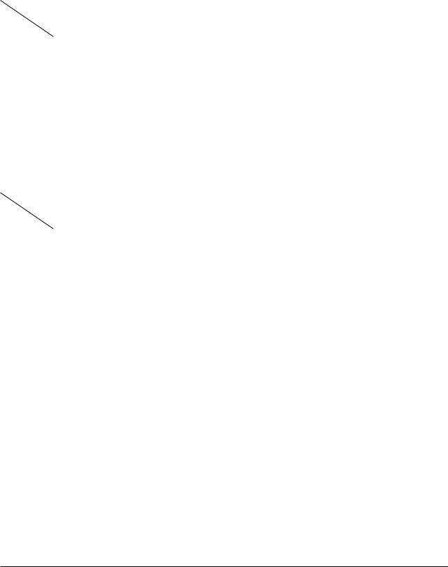
5-1-3 Connecting the SoftJig
Connect the monitor to the signal generator and/ or PC as illustrated in Figures 5-1 and 5-2.
Note: The signal cable connector which includes the 3-wire cable must connect to the monitor. If you use Setup 2 (PC only, no signal generator) you can only make adjustments to the signal timing available on that computer system. To make corrections to all factory timings requires the use of an additional signal generator.
|
MONITOR |
|
INTERFACE |
|
|
BOARD VER. 2.0 |
SIGNAL CABLE |
|
|
||
5V DC |
|
|
ADAPTOR |
7 PIN MINI DIN |
|
|
CONNECTOR |
|
PARALLEL CABLE |
|
|
PC |
SIGNAL |
|
GENERATOR |
||
|
Figure 5-1 : Setup 1, With Signal Generator
|
5 Alignment and Adjustments |
|
MONITOR |
INTERFACE |
|
BOARD VER. 2.0 |
|
5V DC |
7 PIN MINI DIN |
CONNECTOR |
|
ADAPTOR |
|
|
SIGNAL CABLE |
PARALLEL CABLE |
D-SUB |
|
|
PC |
CONNECTOR |
|
Figure 5-2. Setup 2, Without Signal Generator
5-1-4 After Making Adjustments
After finishing all adjustments, test the monitor in all directions. If, for example, the monitor does not meet adjustment specifications when facing north, reposition the monitor to face east and readjust.
This time, try for an adjustment closer to the ideal setting within the tolerance range. Test the unit again in all directions. If the monitor again fails to meet specifications in every direction, contact your Regional After Service Center for possible CRT replacement.
CKA42*7L/5227L |
5-3 |
5 Alignment and Adjustments
5-2 Display Control Adjustments
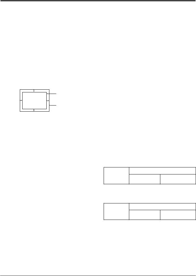
5-2-1 Centering
Centering means to position the center point of the display in the middle of the display area. Horizontal size and position and vertical size and position control the centering of the display.
Adjust the horizontal size and vertical size to their optimal settings: 267 mm (H) x 200 mm (V) for 15”, 255 mm (H) x 191 mm (V) for 14”
Adjust the horizontal position and vertical position to within 4.0 mm of the center point of the screen.
l A - B l ≤ 4.0 mm. l C - D l ≤ 4.0 mm.
|
C |
|
DISPLAY AREA |
A |
B |
|
EDGE OF BEZEL |
|
D |
Figure 5-1. Centering
5-2-1 (a) HORIZONTAL SIZE ADJUSTMENT
CONDITIONS |
|
Scanning frequency: |
53.7 kHz/85 Hz (15”) |
|
43.8 kHz/85 Hz (14”) |
Display image: |
Crosshatch pattern |
Brightness: |
Maximum |
Contrast: |
Maximum |
Adjust the horizontal size of the display pattern to 267 mm (15”) and 255 mm (14”).
(Tolerance ± 3 mm.)
If horizontal size range cannot meet the spec adjust the VR401.
5-2-1 (b) VERTICAL SIZE ADJUSTMENT
CONDITIONS |
|
Scanning frequency: |
53.7 kHz/85 Hz (15”) |
|
43.8 kHz/85 Hz (14”) |
Display image: |
Crosshatch pattern |
Brightness: |
Maximum |
Contrast: |
Maximum |
Adjust the vertical size of the display pattern to
200 mm (15”) and 191 mm (14”). (Tolerance: ± 3 mm.)
5-2-1 (c) HORIZONTAL POSITION ADJUSTMENT
CONDITIONS |
|
Scanning frequency: |
53.7 kHz/85 Hz (15”) |
|
43.8 kHz/85 Hz (14”) |
Display image: |
Crosshatch pattern |
PROCEDURE
Center the test pattern on the raster.
5-2-1 (d) VERTICAL POSITION ADJUSTMENT
CONDITIONS |
|
Scanning frequency: |
53.7 kHz/85 Hz (15”) |
|
43.8 kHz/85 Hz (14”) |
Display image: |
Crosshatch pattern |
Center the test pattern on the raster.
5-2-2 Linearity
Linearity affects the symmetry of images as they appear on the screen. Unless each row or column of blocks in a crosshatch pattern is of equal size, or within the tolerances shown in Tables 5-1 and 5-2, an image appears distorted, elongated or squashed.
The formular of linearity (%)
|
2 x (Max – Min) |
|
= |
|
x 100 |
|
||
|
Max + Min |
|
Table 5-1. Standard Modes Linearity: 800x600/85Hz
Standard Timing Modes
Each block (10 %)
Difference between adjacent blocks (4 %)
Table 5-2. Other Modes Linearity: VGA, SVGA, XGA,
MAC, etc.
Supported Timing Mode
Each block (14 %)
Difference between adjacent blocks (5 %)
5-4 |
CKA42*7L/5227L |
 Loading...