


Automatic drink vending machine
model
Saeco D.A.
3P / 5P
MAINTENANCE MANUAL
Espresso ItaliaANDINSTRUCTIONPTY LTD
www.espressoitalia.com.au
Freecall 1300 660 976

English
MAIN PARTS
|
1 |
|
|
|
|
|
|
|
|
2 |
|
|
|
|
|
|
5 |
|
3 |
|
|
|
|
|
|
|
|
4 |
|
|
|
|
|
|
|
|
|
|
|
6 |
7 |
|
8 |
9 |
27 |
|
|
|
|
|
|
|
|
26 |
|
|
|
|
|
|
|
10 |
|
|
|
|
|
|
|
|
|
30 |
|
|
|
|
|
|
|
11 |
|
|
|
|
|
|
|
|
|
25 |
|
|
|
|
|
|
|
|
24 |
|
|
|
|
|
|
|
12 |
|
|
|
|
|
|
|
|
|
23 |
|
|
|
|
|
|
|
13 |
|
|
|
|
|
|
|
|
|
22 |
|
|
|
|
|
|
|
14 |
|
|
|
|
|
|
|
28 |
|
29 |
21 |
20 |
19 |
18 |
17 |
16 |
15 |
|
fig. 1 |
|
|
|
|
|
|
|
|
1 |
Display |
16 |
Drip tray |
|
2 |
Fault light |
17 |
Hot water nozzle |
|
3 |
Keys (D.A. 3P - D.A. 5P) |
18 |
Drink dispenser |
|
4 |
Coin slot |
19 |
Drain grill |
|
5 |
Silicon bushing (only D.A. 5P) |
20 |
Dispensing slot |
|
6 |
Soluble product container (solo D.A. 5P) |
21 |
Grill stand |
|
7 |
Water tank |
22 |
Mixing chamber (only D.A. 5P) |
|
8 |
Coffee container cover |
23 |
Instant product funnel (only D.A. 5P) |
|
9 |
Coffee bean hopper |
24 |
Door key |
|
10 |
Grinder selecting knob |
25 |
Serial port |
|
11 |
Opening for safety micro-switch bypassing |
26 |
RESET key |
|
12 |
Tank cover with valve |
27 |
Instant product funnel cover (only D.A. 5P) |
|
13 |
Coffee unit |
28 |
Main switch |
|
14 |
Coffee grounds tray |
29 |
Internal access door |
|
15 |
Coin/token box |
30 Clock module door |
Espresso Italia PTY LTD |
|
|
|
|
|
|
2 |
|
|
|
www.espressoitalia.com.au |
|
|
|
|
Freecall 1300 660 976 |

INDEX
MAIN PARTS. ................................................................................................................. |
3 |
||
1 - |
MANUAL OVERVIEW. ........................................................................ |
4 |
|
|
1.1 |
Introduction . .................................................................................... |
4 |
|
1.2 |
Used symbols . .............................................................................. |
4 |
2 - |
MACHINE INFORMATION. ......................................................... |
4 |
|
|
2.1 |
User information . ....................................................................... |
4 |
|
2.2 |
Vending machine intended use . ................................ |
4 |
|
2.3 |
Residual risks . ............................................................................... |
5 |
|
2.4 |
Vending machine identification . ................................ |
5 |
|
2.5 |
Technical specifications . .................................................... |
5 |
3 - |
HANDLING |
|
|
|
AND STORAGE. ........................................................................................... |
6 |
|
4 - SAFETY. |
........................................................................................................................ |
6 |
|
|
4.1 . |
General safety rules ............................................................. |
6 |
|
4.2 . ...................................................... |
Operator requirements |
6 |
|
4.3 . ...................................................... |
Installed safety devices |
6 |
5 - |
INSTRUMENT . ........COMMAND DESCRIPTION |
7 |
|
6 - |
INSTALLATION. ............................................................................................. |
8 |
|
|
6.1 . .......................................... |
List of accessory equipment |
8 |
|
6.2 . .................................................................. |
Water connection |
8 |
|
|
Machine with tank |
|
|
|
(Standard D.A. 3P and |
|
|
. .................................................. |
standard D.A. 5P types) |
8 |
|
|
Machine with direct waterworks connection |
|
|
. ........................ |
(D.A. 3P R.I. e D.A. 5P R.I. types) |
8 |
|
6.3 . ................................................................. |
Electric connection |
9 |
|
6.4 .. ............................ |
PARALLEL 12 V d.c coiner fitting |
9 |
|
6.5 . ..................................................... |
Clock module insertion |
10 |
|
6.6 . ........................................................... |
Nation key insertion |
10 |
|
6.7 . ........................................................ |
Serial port connection |
10 |
|
6.8 . .......................................... |
Affixing labels and stickers |
10 |
7 - PROGRAMMING. ..................................................................................... |
11 |
||
|
7.1 . ........................................................ |
Programming structure |
12 |
|
7.2 . ............................................................................... |
Key functions |
13 |
|
7.3 . .......................................... |
Programming mode access |
13 |
|
7.4 |
Selection of the parameter |
|
|
. ....................................... |
to be changed or displayed |
14 |
English
7.5Changing and memory storing
|
|
parameters. ..................................................................................... |
14 |
|
7.6 |
Menu description. .................................................................... |
14 |
|
|
First main item of |
|
|
|
the programming menu. .................................................... |
14 |
|
|
Second main item of |
|
|
|
the programming menu. .................................................... |
17 |
|
|
Third main item of |
|
|
|
the programming menu. .................................................... |
17 |
|
|
Fourth main item of |
|
|
|
the programming menu. .................................................... |
19 |
|
|
Fifth main item of |
|
|
|
the programming menu. .................................................... |
20 |
8 - |
VENDING MACHINE USE. ........................................................... |
22 |
|
|
8.1 |
Machine statuses. ..................................................................... |
22 |
|
8.2 |
Manual start up. ........................................................................ |
22 |
|
8.3 |
Programmed automatic start up ................................ |
22 |
|
8.4 |
Drink dispensing. ...................................................................... |
22 |
|
8.5 |
First vending machine start up. ................................... |
22 |
|
|
Tank filling. ...................................................................................... |
22 |
|
|
Soluble product container |
|
|
|
(only D.A. 5P). ............................................................................. |
22 |
|
|
Water tank. .................................................................................... |
23 |
|
|
Coffee container. ...................................................................... |
23 |
|
|
Grinding adjustment. ............................................................ |
23 |
|
|
Operations to be performed |
|
|
|
on the vending machine. .................................................. |
23 |
|
|
Coin/token box. ....................................................................... |
24 |
|
8.6 |
Display messages. ................................................................... |
24 |
9 - |
MAINTENANCE. .......................................................................................... |
26 |
|
|
9.1 |
Introduction. .................................................................................... |
26 |
|
9.2 |
Cleaning and maintenance. ......................................... |
27 |
|
|
Coffee unit. ..................................................................................... |
27 |
|
|
Mixer and dispenser (only D.A. 5P). .................... |
27 |
|
|
Soluble powder container. .............................................. |
28 |
|
|
Water tank. .................................................................................... |
28 |
|
|
Dispensing slot area. ............................................................ |
28 |
|
9.3 |
Mix fan replacement. ........................................................... |
28 |
10 -MACHINE SCRAPPING. ................................................................... |
28 |
||
11 -VARIATIONS. ................................................................................................... |
28 |
||
11.1D.A. 3P/5P model
|
(without clock module). ....................................................... |
28 |
11.2 |
Programming structure |
|
|
(V.M 3P standard version and |
|
|
D.A. 5P standard without clock module). ........ |
29 |
Espresso Italia PTY LTD www.espressoitalia.com3 .au
Freecall 1300 660 976
English
1- MANUAL OVERVIEW
1.1Introduction
 Important
This publication is an integral part of the vending machine and should be read carefully. It contains the technical information required for proper installation, maintenance and operation of the D.A. 3P and 5P with clock module. Always refer to this publication before performing any operation.
Figures show the model D.A. 5P, but can also be referred to the model D.A. 3P without substantial differences.
Manufacturer: Cosmec S.p.A.
Via Panigali, 39 - 40041 GAGGIO MONTANO (Bo)
In the internal part of the cover you will find the page with the illustration most frequently referred to by the text. Keep it open while you read the publication.
This publication should be kept with care and must accompany the machine during the whole of its operating life, including ownership changes.
In case this publication is lost or damaged, immediately ask an AUTHORIZED SERVICE CENTRE for a new copy.
• The Manufacturer owns all the copyrights of this publication.
1.2Used symbols
Various types of indications were used in this publication with the purpose of underlining the various danger or competency levels. As a complement to the symbol a message is reported explaining procedures and giving useful information:
 Danger
It’s used to underline dangerous situations for both the vending machine operators and the machine itself.
 Maintenance technician
It’s used to mark out the operations that should be performed only by specialized personnel.
 Important
It’s used to mark out the operations that ensure good vending machine operation if performed.
4
2- MACHINE INFORMATION
2.1User information
•The vending machine is programmable as for the doses of any type of vend.
•The vending machine is pre-set to accommodate the PARALLEL 12V coiner and the mechanic token coiner.
•The vending machine is pre-set for the insertion of an additional function (CLOCK MODULE) that allows start up or shutdown programming.
•In case of need refer to the national Importer or Distributor or to the Manufacturer if the Importer is not available.
•AUTHORIZED SERVICE CENTRES are available for any clarification or information concerning vending machine operation, or to satisfy spare part supply or technical assistance demands.
•The manufacturer reserves the right to carry out improvements to the vending machine without prior notice.
2.2Vending machine intended use
The vending machine D.A. 5P is capable of dispensing in a completely automatic and programmable way:
-espresso coffee prepared with instantly ground bean coffee;
-drinks based on soluble lyophilized products (chocolate, milk, tea, etc.)
-hot water for the preparation of hot drinks
The vending machine D.A. 3P is capable of dispensing in a completely automatic and programmable way:
-espresso coffee prepared with instantly ground bean coffee;
-hot water for the preparation of hot drinks.
 Important
In case of improper use any form of warranty shall decay and the manufacturer shall disclaim all responsibilities for damages to people and/or objects.
The following shall be considered improper uses:
-any use other than the one provided for and/or with techniques different from the ones described in this publication;
-any intervention on the vending machine in contrast with the procedures described in this publication;
-any use after component tampering and/or after changes to the safety devices;
-Installing the device outdoors
Espresso Italia PTY LTD
www.espressoitalia.com.au
Freecall 1300 660 976
2.3Residual risks
The dispensing slot is not protected against accidental contact of hands with the hot liquid.
2.4Vending machine identification
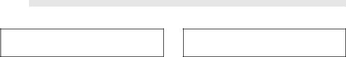
The vending machine is identified by the model name and the registration number, both of which can be found on the identification tag placed in the lower left part of the back panel (fig. 2).
The tag bears the following specifications:
•Manufacturer name
•vending machine model
•some constructive specifications:
-power supply voltage (V)
-power supply frequency (Hz)
-power absorption (W)
•EC marking
•Registration number
•Year of manufacture
 Important
Do not remove or damage the identification tag, as it’s the only element that bears all the information allowing the Manufacturer to identify the vending machine.
For any demand to the AUTHORIZED SERVICE CENTRES (assistance, spare parts, etc.) always refer to this tag, reporting specific vending machine data printed on it.
fig. 2 |
English
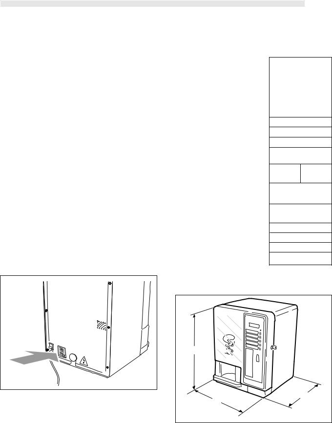
2.5 Technical specifications
Size |
D.A. 5P D.A. 3P |
W. .................................................. |
mm |
D. .................................................... |
mm |
H. .................................................... |
mm |
Weight. ........................................................ |
.kg |
Installed power. ........................................ |
W |
Power supply voltage. ......................... |
V |
Power supply frequency. .................... |
Hz |
Supply cable length. ............................. |
mm |
Capacity |
|
Lyophilized product container. ........ |
kg. |
(extractable, transparent) |
|
Coffee container. .................................... |
kg. |
(extractable, transparent) |
|
Water tank. ................................................ |
litres |
Water supply. ........................................... |
|
. ........................................... |
|
Waterworks pressure. .......................... |
bar |
Waterworks connection. .................... |
|
|
382 |
|
|
355 |
|
|
505 |
|
|
|
|
25 |
|
22.5 |
(*)
(*)
(*)
1500
0.5 to 1.2
1.1
4.8
external tank
waterworks connection
1.5 - 8
3/4" Gas coupling
(*) See tag on the back of the vending machine
A |
P |
L |
fig. 3 |
Espresso Italia PTY LTD www.espressoitalia.com5 .au
Freecall 1300 660 976
English
3- HANDLING AND STORAGE
Handling
The Manufacturer protects the vending machine with cardboard packaging that bears the primary warnings.
•During handling and transportation, the vending machine should remain in a vertical position as per indications printed on the packaging.
•Perform hoisting and positioning operations with care, using adequate means to the load to be hoisted.
•For possible manual hoisting use the special handles placed on the packaging sides.
•Do not lift the vending machine while looking for the grip on the sides of the packaging.
•Do not shake the vending machine.
Storage
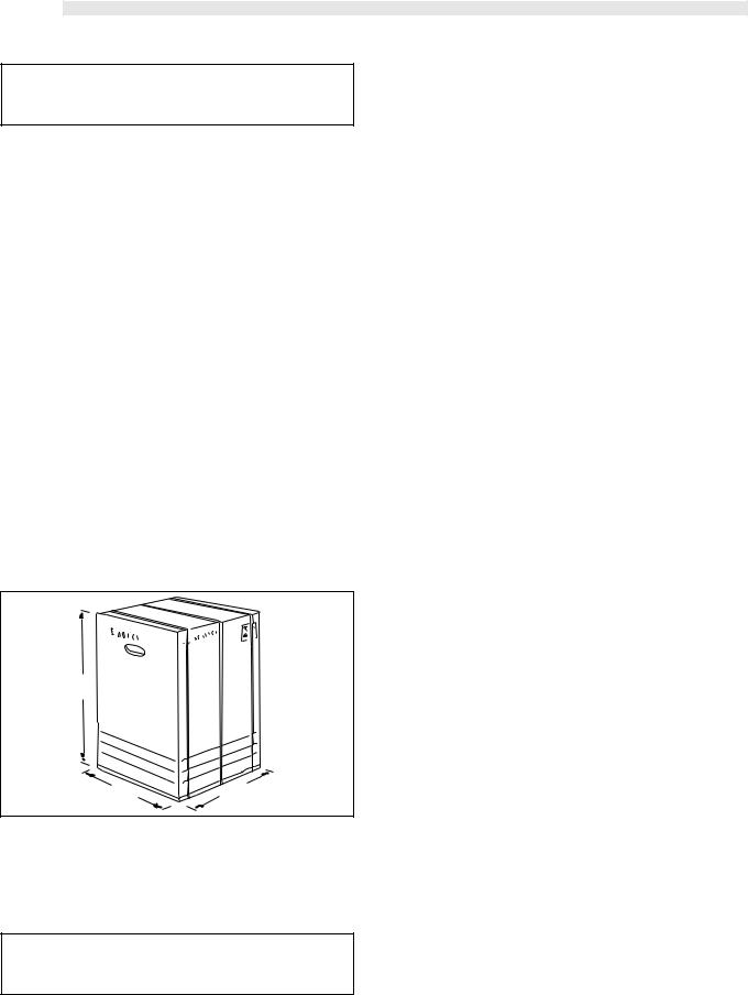
•The vending machine is contained in cardboard packaging with reinforced base (refer to fig. 4).
 Danger
The vending machine packaging can stand 50 kg in weight, therefore do not stack more than two vending machines.
•The vending machine should be stored in its original packaging, in dry and non-dusty places.
650
fig. 4 |
370 |
390 |
|
|
4 - SAFETY
4.1General safety rules
•Carefully read this publication before using the vending machine.
•It’s absolutely forbidden to deactivate the safety devices installed on the vending machine.
6
•Vending machine cleaning and maintenance operations should be performed with the main switch (ref. 28, fig. 1) in the “O” position, or after having removed the plug from the mains outlet.
•Do not try to remove protection plates and panels. If required, call for the assistance of our sales network (addresses in the last page).
•Do not autonomously modify parts of the vending machine; failure in complying with this provision shall result in the cancellation of the Manufacturer’s responsibility.
•Do not aim water squirts on the vending machine.
•Never pour liquids of any type on the vending machine.
•Do not dip the vending machine in water.
4.2Operator requirements
With the purpose of proper vending machine operation and safety, two type of operators with different requirements are defined:
Maintenance technician
Specialized person responsible for vending machine installation, first adjustment and, more in general, specific maintenance.
User
Person with a medium specialization level that has read the norms in the present manual and has followed a proper training course as per laws in force.
The User is allowed to start the vending machine, adjust its working parameters, stop it, carry out its normal loading and coin collection operations, and finally to carry out its external cleaning.
 Danger
The User is forbidden to carry out the operations indicated in the present manual as a specific competency of the maintenance technician.
4.3Installed safety devices
-A safety valve protects the vending machine from overpressures in the hot-water production system.
-The heater is protected against overheating by a thermostat and a thermal fuse.
-A series of micro-switches controls the position of the drip tray (ref. 16, fig. 1), of the vending machine internal access door (ref. 29, fig. 1), of the coffee unit (ref. 13, fig. 1), and of the coffee grounds tray (ref. 14, fig. 1). If one of the components is not in the proper position, the relevant micro-switch stops vending machine operation and the display will show the
message informing about componentEspressoout ofItaliaplace. PTY LTD
www.espressoitalia.com.au
Freecall 1300 660 976
5- COMMAND AND INSTRUMENT DESCRIPTION
 Important
The vending machine is delivered with the dispensing keys already programmed on standard values.
Main switch (ref. 28, fig. 5)
it’s located in the lower right back side of the vending machine.
On the ”I” position it turns the vending machine on (enabling electric functions)
On the “O” position it turns the vending machine off (disables electric functions)
28 |
fig. 5 |
Keypad D.A. 5P (ref. 3, fig. 6)
It’s composed of 5 re-programmable keys that when pressed control the dispensing of the same number of drinks, identified from top to bottom as A - B - C - D - E (ref. 3, fig. 6).
The correspondence between key and dispensed drink is at the User’s discretion.
The A - B - C - D keys (ref. 3, fig. 6) are also used to perform programming.
(refer to “7 - Programming”)
Keypad D.A. 3P (ref. 3, fig. 6)
It’s composed of 3 re-programmable keys that when pressed control the dispensing of the same number of drinks, identified from top to bottom as A - B - C.
The correspondence between key and dispensed drink is at the User’s discretion.
The A - B - C keys (ref. 3, fig. 6) are also used to perform programming.
(refer to “7 - Programming”)
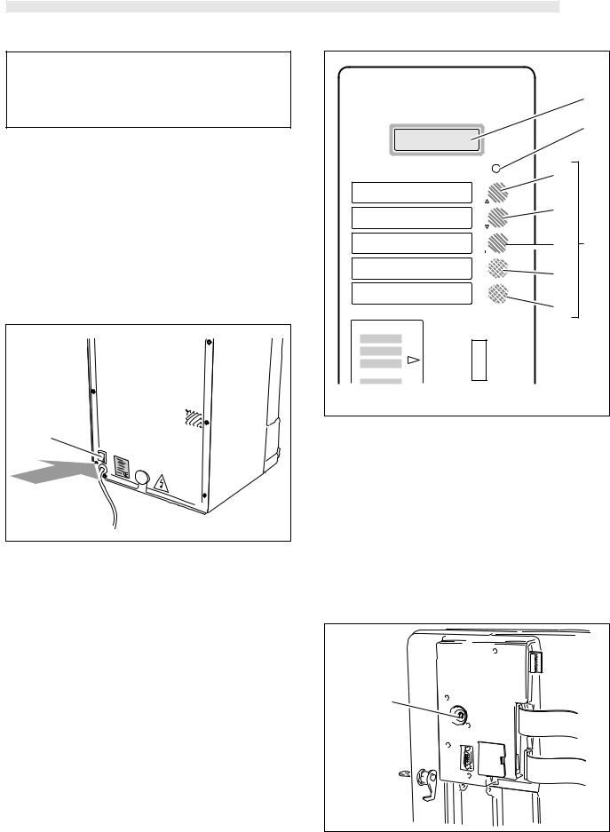
Display (ref. 1, fig. 6)
It’s composed of 2 lines with 16 characters each, and has the duty of displaying the messages relating to the operations (in progress or to be performed) and the possible out-of-service conditions.
|
English |
|
1 |
|
2 |
A |
|
B |
|
C |
3 |
D |
|
E |
|
fig. 6 |
|
Red indicator light (ref. 2, fig. 6)
When the light is on it indicates that the vending machine is not ready for drink dispensing.
In any case the display (ref. 1, fig. 6) supplies the indications on vending machine operative or out-of-service status.
Reset key (ref. 6, fig. 7)
It’s located on the internal part of the door and may perform the following functions:
a)Resetting “OUT OF SERVICE” (out –of-service) indications (refer to “ Display messages ”).
b)Water circuit filling (refer to “ 6.2 Water connection”).
6
fig. 7
Espresso Italia PTY LTD
www.espressoitalia.com7 .au
Freecall 1300 660 976
English
6 - INSTALLATION
 Danger
The presence of strong magnetic fields or the vicinity of electric machines generating strong disturbances might cause malfunctioning of the vending machine electronic control.
-Install the vending machine in a protected environment with
temperatures varying between 10°C and 40 °C.
-Make sure that no tampering occurred during transportation, checking that original packaging is intact and closed with straps.
-Move the closed box near the installation area (refer to “3 Handling and storage”), cut the straps and lift the carton.
-Verify the state and the model of the vending machine contained in the carton.
-Check the contents of the accessory envelope attached to the
vending machine (refer to “6.2 List of accessory equipment).
-Remove the vending machine from the original packaging. It is advisable to keep the latter for later transportation or moving.
-Free the vending machine from residual packaging.
 Important
Possible packaging element disposal shall be performed in compliance with the laws in force in the country while respecting the environment.
-Place the vending machine on a horizontal plane surface hav-
ing adequate size and capable of standing its weight. The bearing surface shall not exceed an inclination of 2°.
 Important
To ensure proper vending machine ventilation, the machine’s rear panel should be at least 8 cm away from walls, partitions, etc.
Do not cover the vending machine with cloths or other things.
6.1List of accessory equipment
•Micro operation key for safety system deactivation
•4 screws and nuts for coiner fixing
•Series of stickers with prices and accepted coins
•Series of stickers with instructions and dispensed products
•1 coupling for water pipe to tank (only for pre-set version with tank)
•1 wrench for mix fan fitting
•1 Operation and Maintenance booklet
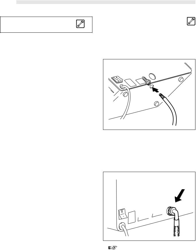
6.2 Water connection
Machine with tank into the floor cabinet
-Fit the special water connection.
-Insert the water aspiration tube in the special connection under the dispenser (fig. 8).
-Insert the tube in the can.
fig. 8 |
Machine with direct waterworks connection
(Type D.A. 3P R.I. e D.A. 5P R.I.)
-Connect the vending machine to a drinking water distribution conduit having a pressure between 1,5 and 8 bar.
To do this use a loading tube with adequate characteristics and connect it to the G3/4” coupling located on the vending machine back panel (fig. 9).
fig. 9 |
Important |
It is advisable to feed the vending machine with treated water by means of a decalcifying device, especially when the water has high calcium and magnesium salts content (hard water).
Espresso Italia PTY LTD
8 www.espressoitalia.com.au
Freecall 1300 660 976

6.3 Electrical connection
The vending machine is pre-set for electrical operation with a sin- gle-phase voltage whose value is stated in the identification tag (Refer to “2.4 Vending machine identification”) (fig. 2).
 Danger
The connection point of the electric outlet must be located in a place that can be easily reached by the user, so that he can easily disconnect the vending machine from the power supply when required.
Before connecting, make sure that:
•The mains supply voltage of the outlet the vending machine is connected to corresponds to the one indicated on the tag.
•The electric installation of the place where the vending machine is going to be installed complies with the laws in force, and has the characteristics enabling it to stand the required maximum load indicated on the tag.
Check the electric installation’s compliance with the safety rules in force; in case of doubt, require an accurate electric installation survey by qualified professional staff.
 Danger
The use of adapters or patch cords is forbidden.
|
fig. 10 |
6.4Fitting the
PARALLEL 12 V d.c. coiner
Only 12 V d.c. parallel or mechanical coiners may be used on this vending machine.
-Remove the token accepting device support (fig. 11).
-Drill a hole on the keypad panel (fig. 11).
English
fig. 11
-Insert the coiner and fix it by using the 4 supplied screws with nuts (fig. 12).
-Connect the flat cable to the coiner (fig. 12).
fig. 12
-Connect the flat cable to the electronic board (fig. 13).
fig. 13
 Important
The Company disclaims all responsibilities for damages to vending machine, properties and people arising out of improper installation of the payment system; this responsibility falls directly on whoever performed the fitting.
Espresso Italia PTY LTD www.espressoitalia.com9 .au
Freecall 1300 660 976

English
6.5Insertion of the Clock module 
 Danger
This operation should be carried out by the maintenance technician.
The “Clock Module” device manages the following functions:
-the times when free dispensing is performed;
-Vending machine start up and shutdown times;
-the times when discounts or price rises should be applied, and their amount;
-cleaning frequency
The following operations should be performed to insert the module:
-disconnect the device from the power supply;
-open the vending machine door (ref. 29, fig. 1) and remove the small door (ref. D, fig. 14);
-insert the module (ref. A, fig. 14) in the electronic board connector.
Important
The module (ref. A, fig. 13) is inserted properly when the reference mark is in the lower part (fig. 14).
-Re-fit the small door (ref. D, fig. 14).
-Re-close the door (ref. 29, fig. 1).
B
C
A
 D
D
fig. 14
6.6 Insertion of the Nation key
 Danger
This operation should be carried out by the maintenance technician.
The “nation key” contains the following data:
-Language used by the display.
-Software settings connected with the country of operation.
Important
The vending machine does NOT work without the “nation key” inserted, it is therefore necessary to insert it.
After having inserted the “nation key”, the machine will refuse the introduction of keys for different countries.
10
To insert the nation key it’s necessary to perform the following operations:
-Disconnect the power supply.
-Open the vending machine internal access door (fig. 14).
-Insert the key (ref. B, fig. 14) in the electronic board connector.
-Re-close the door.
6.7 Serial port connection
 Danger
This operation should be carried out by the maintenance technician.
A serial port (ref. C, fig. 14) is installed beside the “clock module” connector.
Through the serial port the vending machine may be connected to a Personal Computer or to the devices supplied to the AUTHORIZED SERVICE CENTRES in order to carry out inspections and programming operations.
6.8Affixing labels and stickers
Separate the accessory drink labels supplied with the machine by following the broken line.
Apply the adhesive prices on the drink labels.
Insert the tags in the special housings (fig. 15-16) through the slots located in the internal part of the door (ref. 29, fig. 1).
fig. 15
fig. 16 |
Espresso Italia PTY LTD |
|
www.espressoitalia.com.au
Freecall 1300 660 976
 Loading...