


OPERATOR’S MANUAL
MANUEL D’UTILISATION
MANUAL DEL OPERADOR
FIXED BASE ROUTER
DOUBLE INSULATED
TOUPIE À BASE FIXE
DOUBLE ISOLATION
FRESADORA DE BASE FIJA
DOBLE AISLAMIENTO
R163 / R163G
TABLE OF CONTENTS |
TABLE DES MATIÈRES |
|
|
ÍNDICE DE CONTENIDO |
|
|||
**************** |
|
**************** |
|
|
|
**************** |
|
|
General Power Tool Safety |
|
Règles de sécurité relatives |
|
Advertencias de seguridad |
|
|||
Warnings.......................................... |
2-3 |
aux outils électriques....................... |
|
2-3 |
|
para herramientas eléctricas.......... |
2-3 |
|
Router Safety Warnings...................... |
3 |
Avertissements de sécurité |
|
Advertencias de seguridad tupi......... |
3 |
|||
Symbols |
4 |
relatifs au toupie................................. |
|
3 |
Símbolos |
|
4 |
|
Symboles |
|
4 |
|
|||||
Electrical |
5 |
|
|
Aspectos eléctricos |
|
5 |
||
Caractéristiques électriques |
5 |
|
||||||
Features |
6 |
Características |
|
6 |
||||
Caractéristiques |
|
6 |
|
|||||
Assembly |
6 |
|
Armado |
|
6 |
|||
Assemblage |
|
6 |
|
|||||
Operation |
6-11 |
|
Funcionamiento |
|
6-11 |
|||
Utilisation |
|
6-11 |
|
|||||
Adjustments |
11 |
|
|
Ajustes |
|
11 |
||
Réglages |
|
11 |
|
|||||
Maintenance |
12 |
|
Mantenimiento |
|
12 |
|||
Entretien |
|
12 |
|
|||||
Accessories |
12 |
|
Accesorios |
|
12 |
|||
Accessoires |
|
12 |
|
|||||
Figures (Illustrations) |
13-16 |
|
Figuras (illustraciones) |
|
13-16 |
|||
Figures (illustrations) |
|
13-16 |
|
|||||
Parts Ordering and |
|
|
Pedidos de piezas |
|
|
|||
|
|
|
|
|
|
|||
Service................................. |
Back page |
Commande de pièces |
|
|
|
y servicio....................... |
Pág. posterior |
|
|
|
et dépannage..................... |
Page arrière |
|
|
|
|
|
WARNING: To reduce the |
AVERTISSEMENT : Pour |
ADVERTENCIA: Para |
risk of injury, the user must read and |
réduire les risques de blessures, |
reducir el riesgo de lesiones, el usuario |
understandtheoperator’smanualbefore |
l’utilisateur doit lire et veiller à bien |
debe leer y comprender el manual del |
using this product. |
comprendrelemanueld’utilisationavant |
operador antes de usar este producto. |
|
d’employer ce produit. |
|
SAVE THIS MANUAL FOR |
CONSERVER CE MANUEL |
GUARDE ESTE MANUAL |
FUTURE REFERENCE |
POUR FUTURE RÉFÉRENCE |
PARA FUTURAS CONSULTAS |

GENERAL POWER TOOL SAFETY WARNINGS
 WARNING
Read all safety warnings and all instructions. Failure to follow the warnings and instructions may result in electric shock, fire and/or serious injury.
Save all warnings and instructions for future reference.
The term “power tool” in the warnings refers to your mainsoperated (corded) power tool or battery-operated (cordless) power tool.
WORK AREA SAFETY
Keep work area clean and well lit. Cluttered or dark areas invite accidents.
Do not operate power tools in explosive atmospheres, such as in the presence of flammable liquids, gases or dust. Power tools create sparks which may ignite the dust or fumes.
Keep children and bystanders away while operating a power tool. Distractions can cause you to lose control.
ELECTRICAL SAFETY
Power tool plugs must match the outlet. Never modify the plug in any way. Do not use any adapter plugs with earthed (grounded) power tools. Unmodified plugs and matching outlets will reduce risk of electric shock.
Avoid body contact with earthed or grounded surfaces such as pipes, radiators, ranges and refrigerators. There is an increased risk of electric shock if your body is earthed or grounded.
Do not expose power tools to rain or wet conditions.
Water entering a power tool will increase the risk of electric shock.
Do not abuse the cord. Never use the cord for carrying, pulling or unplugging the power tool. Keep cord away from heat, oil, sharp edges or moving parts. Damaged or entangled cords increase the risk of electric shock.
When operating a power tool outdoors, use an extension cord suitable for outdoor use. Use of a cord suitable for outdoor use reduces the risk of electric shock.
If operating a power tool in a damp location is unavoidable, use a ground fault circuit interrupter (GFCI) protected supply. Use of a GFCI reduces the risk of electric shock.
PERSONAL SAFETY
Stay alert, watch what you are doing and use common sense when operating a power tool. Do not use a power tool while you are tired or under the influence of drugs, alcohol or medication. A moment of inattention while operating power tools may result in serious personal injury.
Use personal protective equipment. Always wear eye protection. Protective equipment such as dust mask, nonskid safety shoes, hard hat, or hearing protection used for appropriate conditions will reduce personal injuries.
Prevent unintentional starting. Ensure the switch is in the off-position before connecting to power source and/or battery pack, picking up or carrying the tool.
Carrying power tools with your finger on the switch or energising power tools that have the switch on invites accidents.
Remove any adjusting key or wrench before turning the power tool on. A wrench or a key left attached to a rotating part of the power tool may result in personal injury.
Do not overreach. Keep proper footing and balance at all times. This enables better control of the power tool in unexpected situations.
Dress properly. Do not wear loose clothing or jewellery. Keep your hair, clothing and gloves away from moving parts. Loose clothes, jewellery or long hair can be caught in moving parts.
If devices are provided for the connection of dust extraction and collection facilities, ensure these are connected and properly used. Use of dust collection can reduce dust-related hazards.
Do not wear loose clothing or jewelry. Contain long hair. Loose clothes, jewelry, or long hair can be drawn into air vents.
Do not use on a ladder or unstable support. Stable footing on a solid surface enables better control of the power tool in unexpected situations.
POWER TOOL USE AND CARE
Do not force the power tool. Use the correct power tool for your application. The correct power tool will do the job better and safer at the rate for which it was designed.
Do not use the power tool if the switch does not turn it on and off. Any power tool that cannot be controlled with the switch is dangerous and must be repaired.
Disconnect the plug from the power source and/or the battery pack from the power tool before making any adjustments, changing accessories, or storing power tools. Such preventive safety measures reduce the risk of starting the power tool accidentally.
Store idle power tools out of the reach of children and do not allow persons unfamiliar with the power tool or these instructions to operate the power tool. Power tools are dangerous in the hands of untrained users.
Maintain power tools. Check for misalignment or binding of moving parts, breakage of parts and any other condition that may affect the power tool’s operation. If damaged, have the power tool repaired before use.
Many accidents are caused by poorly maintained power tools.
2 − English

GENERAL POWER TOOL SAFETY WARNINGS
Keep cutting tools sharp and clean. Properly maintained cutting tools with sharp cutting edges are less likely to bind and are easier to control.
Use the power tool, accessories and tool bits etc. in accordance with these instructions, taking into account the working conditions and the work to be performed. Use of the power tool for operations different from those intended could result in a hazardous situation.
SERVICE
Have your power tool serviced by a qualified repair person using only identical replacement parts. This will ensure that the safety of the power tool is maintained.
When servicing a power tool, use only identical replacement parts. Follow instructions in the Maintenance section of this manual. Use of unauthorized parts or failure to follow Maintenance instructions may create a risk of shock or injury.
ROUTER SAFETY WARNINGS
Hold power tool by insulated gripping surfaces, because the cutter may contact its own cord. Cutting a “live” wire may make exposed metal parts of the power tool “live” and shock the operator.
Use clamps or another practical way to secure and support the workpiece to a stable platform. Holding the work by your hand or against the body leaves it unstable and may lead to loss of control.
Know your power tool. Read operator’s manual carefully. Learn its applications and limitations, as well as the specific potential hazards related to this tool.
Following this rule will reduce the risk of electric shock, fire, or serious injury.
Always wear eye protection with side shields marked to comply with ANSI Z87.1. Following this rule will reduce the risk of serious personal injury.
Protect your lungs. Wear a face or dust mask if the operation is dusty. Following this rule will reduce the risk of serious personal injury.
Protect your hearing. Wear hearing protection during extended periods of operation. Following this rule will reduce the risk of serious personal injury.
Inspect tool cords periodically and, if damaged, have repaired at your nearest authorized service center. Constantly stay aware of cord location. Following this rule will reduce the risk of electric shock or fire.
Check damaged parts. Before further use of the tool, a guard or other part that is damaged should
be carefully checked to determine that it will operate properly and perform its intended function. Check for alignment of moving parts, binding of moving parts, breakage of parts, mounting, and any other conditions that may affect its operation. A guard or other part that is damaged should be properly repaired or replaced by an authorized service center. Following this rule will reduce the risk of shock, fire, or serious injury.
Make sure your extension cord is in good condition. When using an extension cord, be sure to use one heavy enough to carry the current your product will draw. A wire gauge size (A.W.G.) of at least 14 is recommended for an extension cord 50 feet or less in length. A cord exceeding 100 feet is not recommended. If in doubt, use the next heavier gauge. The smaller the gauge number, the heavier the cord. An undersized cord will cause a drop in line voltage resulting in loss of power and overheating.
Inspect for and remove all nails from lumber before using this tool. Following this rule will reduce the risk of serious personal injury.
If the power supply cord is damaged, it must be replaced only by the manufacturer or by an authorized service center to avoid risk.
Save these instructions. Refer to them frequently and use them to instruct others who may use this product. If you loan someone this product, loan them these instructions also.
3 − English
SYMBOLS
The following signal words and meanings are intended to explain the levels of risk associated with this product.
SYMBOL |
SIGNAL |
MEANING |
|
|
|
|
DANGER: |
Indicates an imminently hazardous situation, which, if not avoided, will result |
|
in death or serious injury. |
|
|
|
|
|
|
|
|
WARNING: |
Indicates a potentially hazardous situation, which, if not avoided, could result |
|
in death or serious injury. |
|
|
|
|
|
|
|
|
CAUTION: |
Indicates a potentially hazardous situation, which, if not avoided, may result in |
|
minor or moderate injury. |
|
|
|
|
|
|
|
|
NOTICE: |
(Without Safety Alert Symbol) Indicates important information not related to an |
|
injury hazard, such as a situation that may result in property damage. |
|
|
|
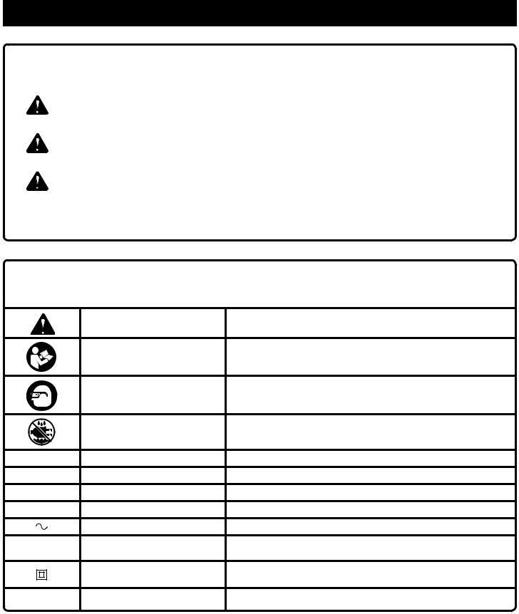
Some of the following symbols may be used on this product. Please study them and learn their meaning. Proper interpretation of these symbols will allow you to operate the product better and safer.
SYMBOL |
NAME |
DESIGNATION/EXPLANATION |
|
Safety Alert |
Indicates a potential personal injury hazard. |
|
Read Operator’s Manual |
To reduce the risk of injury, user must read and understand |
|
operator’s manual before using this product. |
|
|
|
|
|
Eye Protection |
Always wear eye protection with side shields marked to comply |
|
with ANSI Z87.1. |
|
|
|
|
|
Wet Conditions Alert |
Do not expose to rain or use in damp locations. |
V |
Volts |
Voltage |
A |
Amperes |
Current |
Hz |
Hertz |
Frequency (cycles per second) |
min |
Minutes |
Time |
|
Alternating Current |
Type of current |
no |
No Load Speed |
Rotational speed, at no load |
|
Class II Construction |
Double-insulated construction |
.../min |
Per Minute |
Revolutions, strokes, surface speed, orbits etc., per minute |
4 − English

ELECTRICAL
DOUBLE INSULATION
Double insulation is a concept in safety in electric power tools, which eliminates the need for the usual threewire grounded power cord. All exposed metal parts are isolated from the internal metal motor components with protecting insulation. Double insulated tools do not need to be grounded.
 WARNING:
The double insulated system is intended to protect the user from shock resulting from a break in the product’s internal insulation. Observe all normal safety precautions to avoid electrical shock.
NOTE: Servicing of a product with double insulation requires extreme care and knowledge of the system and should be performed only by a qualified service technician. For service, we suggest you return the product to your nearest authorized service center for repair. Always use original factory replacement parts when servicing.
ELECTRICAL CONNECTION
This product has a precision-built electric motor. It should be connected to a power supply that is 120 volts, AC only (normal household current), 60 Hz. Do not operate this product on direct current (DC). A substantial voltage drop will cause a loss of power and the motor will overheat. If the product does not operate when plugged into an outlet, double-check the power supply.
EXTENSION CORDS
When using a power tool at a considerable distance from a power source, be sure to use an extension cord that has the capacity to handle the current the tool will draw. An undersized cord will cause a drop in line voltage, resulting in overheating and loss of power. Use the chart to determine the minimum wire size required in an extension cord. Only round jacketed cords listed by Underwriter’s Laboratories (UL) should be used.
When working outdoors with a product, use an extension cord that is designed for outside use. This type of cord is designated with “W-A” or “W” on the cord’s jacket.
Before using any extension cord, inspect it for loose or exposed wires and cut or worn insulation.
**Ampere rating (on product data plate) |
|
|
|
|||
|
0-2.0 |
2.1-3.4 3.5-5.0 |
5.1-7.0 |
7.1-12.0 |
12.1-16.0 |
|
Cord Length |
|
Wire Size (A.W.G.) |
|
|
||
|
|
|
|
|
|
|
25' |
16 |
16 |
16 |
16 |
14 |
14 |
|
|
|
|
|
|
|
50' |
16 |
16 |
16 |
14 |
14 |
12 |
|
|
|
|
|
|
|
100' |
16 |
16 |
14 |
12 |
10 |
— |
|
|
|
|
|
|
|
**Used on 12 gauge - 20 amp circuit. NOTE: AWG = American Wire Gauge
 WARNING:
Keep the extension cord clear of the working area. Position the cord so that it will not get caught on lumber, tools, or other obstructions while you are working with a power tool. Failure to do so can result in serious personal injury.
 WARNING:
Check extension cords before each use. If damaged replace immediately. Never use product with a damaged cord since touching the damaged area could cause electrical shock resulting in serious injury.
5 − English

FEATURES
PRODUCT SPECIFICATIONS
Depth of Cut.................................................................. |
2 in. |
No Load Speed.................................... |
25,000 r/min (RPM) |
Collet.......................................................................... |
1/4 in. |
Input................................ |
120 V, 60 Hz, AC only, 8.5 Amps |
Peak Horsepower.................................................... |
1.5 HP |
|
|
ASSEMBLY
 WARNING:
Do not use this product if it is not completely assembled or if any parts appear to be missing or damaged. Use of a product that is not properly and completely assembled or with damaged or missing parts could result in serious personal injury.
 WARNING:
Do not attempt to modify this product or create accessories or attachments not recommended for use with this product. Any such alteration or modification is misuse and could result in a hazardous condition leading to possible serious personal injury.
If any parts are damaged or missing, please call 1-800-525-2579 for assistance.
CALIFORNIA PROPOSITION 65
 WARNING:
This product and some dust created by power sanding, sawing, grinding, drilling, and other construction activities may contain chemicals, including lead, known to the State of California to cause cancer, birth defects, or other reproductive harm. Wash hands after handling.
Some examples of these chemicals are:
•lead from lead-based paints,
•crystalline silica from bricks and cement and other masonry products and,
•arsenic and chromium from chemically treated lumber.
Your risk from exposure to these chemicals varies, depending on how often you do this type of work. To reduce your exposure, work in a well-ventilated area and with approved safety equipment, such as dust masks that are specially designed to filter out microscopic particles.
OPERATION
WARNING:
Do not allow familiarity with tools to make you careless. Remember that a careless fraction of a second is sufficient to inflict serious injury.
APPLICATIONS
You may use this tool for the purposes listed below:
nRout grooves, carve designs, mortise door jambs, and create joints in wood and wood products
nCabinet making, routing counter tops, and finishing work in wood and wood products
WARNING:
Always wear eye protection with side shields marked to comply with ANSI Z87.1. Failure to do so could result in objects being thrown into your eyes, resulting in possible serious injury.
REMOVING/INSTALLING ROUTER BASE
See Figure 1, page 14.
To remove the base:
nUnplug the router.
nPlace the router upside down with the Ryobi label away from you.
6 − English

OPERATION
nLoosen the lock lever on the base.
NOTE: It should not be possible to move the router motor with the lock lever tightened and the motor correctly installed in either base. If movement is possible with the lock lever tightened in either of the bases, an adjustment to the lock lever needs to be made. See
Adjustments.
nHold the handles and pull the adjustment bar from the slot in the motor base.
nLift the base up from the slot until the adjustment bar tab passes out of the slot area.
nAfter the tab has cleared the slot, release the adjustment bar and press the spindle lock down and in (until it fully locks in the collet spindle) so that it slides behind the base housing.
NOTE: When using the spindle lock for any application, make sure that the latch goes all the way in. If the latch is depressed and does not go all the way in, turn the collet with the wrench provided until the spindle lock locks into place.
nPull the base until it dislodges from the motor. Use caution, as forcing may result in permanent damage to the locking mechanism.
To install the base:
nUnplug the router.
nWith the base right side up, loosen the lock lever.
nPush the spindle lock in, holding it into place.
nAlign arrow on base with arrow on motor.
nPush the base until it lodges into the motor housing. The spindle lock can be released once the motor slides down into the base. It will disengage once it has cleared the inside of the base. Use caution as forcing may result in permanent damage to the locking mechanism.
nPull the adjustment bar.
nPlace the adjustment bar tab in the slot on the motor.
nTighten the lock lever.
WARNING:
If the collet nut is not securely tightened, the bit may detach during use, causing serious personal injury.
WARNING:
Never use bits which are larger in diameter than the opening in the router subbase. These situations could cause possible loss of control or create other hazardous conditions that could cause possible serious personal injury.
NOTICE:
To prevent damage to the spindle or spindle lock, always allow motor to come to a complete stop before engaging the spindle lock.
WARNING:
If you are changing a bit immediately after use, be careful not to touch the collet nut, bit, or collet with your hands or fingers. You will get burned because of the heat buildup from cutting. Always use the wrench provided.
WARNING:
Bit continues to rotate after the router has been turned off. To avoid injury, wait until the bit has come to a complete stop before removing router from the workpiece.
INSTALLING/REMOVING BITS
See Figure 2, page 14.
nUnplug the router.
To install the bit:
nPush the spindle lock down and in, holding it into place.
nLoosen the collet nut and remove the bit.
nInsert the bit until it is approximately 1/8 in. to 1/4 in. away from the collet nut face.
NOTE: Make sure that the collet always clamps the shank (non-cutting end) of the bit.
nTighten the collet nut securely by turning it clockwise with the wrench provided.
nRelease the spindle lock.
To remove the bit:
nPush the spindle lock down and in, holding it into place.
nLoosen the collet nut and remove the bit.
nRelease the spindle lock.
LED WORKLIGHT
See Figure 3, page 14.
The two LED worklights on the base of the router motor will come on when the on/off switch is in the ON ( I ) position. This provides additional lighting on the surface of the workpiece for operation in lower-light areas.
7 − English

OPERATION
SELECTING DEPTH OF CUT
Proper depth of cut depends on several factors: the horsepower of the router motor, the type of bit, and the type of wood. A lightweight, low horsepower router is designed for making shallow cuts; a router with higher horsepower is designed for deeper cuts. Small bits, such as veining bits with 1/16 in. cutting diameters, are designed to remove only small amounts of wood. Large bits, such as straight-flute bits, remove larger amounts of wood and make deeper cuts in soft woods, such as white pine.
Choose a depth of cut that will not place excessive strain on the router motor. If you need extra force or the motor speed slows down considerably, turn off the router and reduce the depth of cut. Then, make the cut in two or more passes.
When routing a groove that is too deep to safely cut in one pass, make the cut in several passes. We recommend that cuts be made at a depth not exceeding 1/8 in. and that several passes be made to reach deeper cuts.
SETTING DEPTH OF CUT
See Figures 4 - 5, page 14.
The bit depth can be adjusted by turning the depth adjustment knob clockwise or counterclockwise. The depth of the cut can be read on the depth adjustment knob. Each mark on the scale indicates a 1/128 in. change in depth setting.
nUnplug the router.
nLoosen the lock lever.
nTurn the depth adjustment knob counterclockwise to move the collet down or clockwise to move the collet up.
NOTE: It should not be possible to make depth adjustments with the lock lever tightened. If depth adjustments are possible with the lock lever tightened, an adjustment to the lock lever needs to be made. See Adjustments.
nWhen the desired depth of cut is set, tighten the lock lever.
To use the quick release button:
nUnplug the router.
nLoosen the lock lever.
nPress and hold the quick release button while moving the router motor up or down in the base.
When the router is mounted to a router table, depth adjustments can be made easily by using a T-handle wrench.
To make through table adjustments:
nUnplug the router.
nLoosen the lock lever.
nInsert a T-handle wrench through the hole in the router table into the hole on the subbase, and place the end of the wrench socket over the adjusting nut.
nTurn the wrench counterclockwise to move the collet down or clockwise to move the collet up.
NOTE: It should not be possible to make depth adjustments with the lock lever tightened. If depth adjustments are possible with the lock lever tightened, an adjustment to the lock lever needs to be made. See Adjustments.
nWhen the desired depth of cut is set, tighten the lock lever.
WARNING:
Do not use with router tables that fail to conform to safe woodworking practices and offer proper guarding for the bit. Use router tables that are UL classified and identified suitable for use with the specific router model. Failure to comply can result in an accident causing possible injury.
WARNING:
Only use router tables with proper guarding for the bit and with on-board switch controlled receptacles. Failure to use router tables with appropriate safety features could result in serious personal injury.
TURNING THE ROUTER ON AND OFF
See Figure 6, page 14.
To turn the router on, push the switch to the ( I ), or ON position. Return the switch to the ( O ), or OFF position when routing operation is finished.
OPERATING THE ROUTER
When routing straight cuts across a workpiece, clamp a straight edge to the workpiece to use as a guide.
NOTE: Edge guides for the router are also available. See
Accessories.
Position the straight edge parallel to the line of cut and offset the distance between the cutting edge of the bit and the edge of the router base. Hold the router base against the straight edge and rout the groove.

OPERATION
When routing a groove, the travel should be in a direction |
n Rout the pattern in two or more passes. Make the first |
||
that places the guide you are using at the right-hand side. |
pass at 25% of the desired depth of cut. This will provide |
||
When the guide is positioned as shown in the “guide inside” |
better control as well as being a guide for the next pass. |
||
illustration, tool travel should be from left to right and coun- |
NOTE: Do not rout deeper than 1/8 in. per pass. |
||
terclockwise around curves. When the guide is positioned as |
EDGING WITH PILOT BIT |
||
shown in the “guide outside” illustration, tool travel should |
|||
be from right to left and clockwise around curves. If there |
See Figure 10, page 15. |
||
is a choice, the first setup is generally the easier to use. In |
The arbor type bits with pilots are excellent for quick, easy, |
||
either case, the sideways thrust you use is against the guide. |
edge shaping of any workpiece edge that is either straight |
||
INTERNAL ROUTING |
or curved at a curvature as great or greater than the radius |
||
of the bit to be used. The pilot prevents the bit from mak- |
|||
See Figure 7, page 15. |
|||
ing too deep a cut; and holding the pilot firmly in contact |
|||
n Tilt router and place on workpiece without the bit contact- |
|||
with the workpiece edge throughout prevents the cut from |
|||
ing the workpiece. |
becoming too shallow. |
||
n Turn the router on and let the motor build up to full speed. |
Whenever the workpiece thickness together with the desired |
||
n Gradually |
feed bit into the workpiece until the subbase |
depth of cut (as adjusted by router depth setting) are such |
|
is level with the workpiece. |
that only the top part of the edge is to be shaped (leaving |
||
n Upon completion of the cut, turn the router off and let the |
at least a 1/16 in. thick uncut portion at bottom), the pilot |
||
bit come to a complete stop before removing the router |
can ride against the uncut portion, which serves to guide it. |
||
However, if the workpiece is too thin or the bit set too low |
|||
from the workpiece. |
|||
so that there will be no uncut edge to ride the pilot against, |
|||
|
|
||
EDGE ROUTING |
an extra board to act as a guide must be placed under the |
||
See Figure 8, page 15. |
workpiece. This “guide” board must have exactly the same |
||
n Clamp a straight edge to the workpiece as a guide. |
contour— straight or curved—as the workpiece edge. If it is |
||
positioned so that its edge is flush with the workpiece edge, |
|||
|
|
||
n P lace the router on the edge of the workpiece without |
|||
the bit contacting the workpiece. |
the bit will make a full cut (in as far as the bit radius). On the |
||
other hand, if the guide is positioned as shown in figure 10 |
|||
n Turn router on and let the motor build up to full speed. |
|||
(out from the workpiece edge), the bit will make less than |
|||
n Gradually feed the bit into the workpiece using the |
a full cut — which will alter the shape of the finished edge. |
||
clamped straight edge as a guide. |
NOTE: Any of the piloted bits can be used without a pilot for |
||
n Upon completion of the cut, turn the router off and let the |
edge shaping with guides, as preceding. The size (diameter) |
||
bit come to a complete stop before removing the router |
of the pilot that is used determines the maximum cut width |
||
from the workpiece. |
that can be made with the pilot against the workpiece edge |
||
|
|
(the small pilot exposes all of the bit; the large one reduces |
|
WARNING: |
this amount by 1/16 in.). |
|
Do not use large router bits for freehand routing. Use of large router bits when freehand routing could cause loss of control or create other hazardous conditions that could result in personal injury. If using a router table, large bits should be used for edging only.
FREEHAND ROUTING
See Figure 9, page 15.
When used freehand, the router becomes a flexible and versatile tool. This flexibility makes it possible to easily rout signs, relief sculptures, etc. When freehand routing:
nDraw or layout the pattern on the workpiece.
nChoose the appropriate bit.
NOTE: A core box or V-groove bit is often used for routing letters and engraving objects. Straight bits and ball mills are often used to make relief carvings. Veining bits are used to carve small, intricate details.
DIRECTION OF FEED AND THRUST
See Figures 11 - 12, page 15.
The router motor and bit revolve in a clockwise direction. This gives the tool a slight tendency to twist in a counterclockwise direction, especially when the motor revs up.
Feed the router into the workpiece from left to right. When fed from left to right, the rotation of the bit pulls the router against the workpiece. If fed in the opposite direction, the rotation of the spinning bit will tend to throw the router away from the workpiece causing kickback. This could cause you to lose control of the router.
Because of the high speed of bit rotation during a proper feeding operation, there is very little kickback under normal conditions. However, if the bit strikes a knot, hard grain, or foreign object that affects the normal progress of the cutting action, there will be a slight kickback. The direction of kickback is always in the direction opposite bit rotation. This will affect the trueness of the cut.
9 − English

OPERATION
To guard against kickback, plan the setup and direction of feed so that you will always be thrusting the tool in the same direction that the leading edge of the bit is moving. The thrust should be in a direction that keeps the sharp edges of the bit continuously biting straight into new (uncut) wood.
NOTE: For best results, make sure to take enough time to set up for cutting. While cutting, make sure to use the proper rate of feed.
PROPER RATE OF FEED
Professional routing depends upon careful setup and proper rate of feed which is learned through practice and use. The proper rate of feed is dependent upon:
hardness and moisture content of the workpiece
depth of cut
cutting diameter of the bit
When cutting shallow grooves in soft woods such as pine, a faster rate of feed can be used. When making cuts in hardwoods such as oak, a slower rate of feed is required.
Several factors will help you select the proper rate of feed.
Choose the rate that does not slow down the motor.
Choose the rate at which the bit advances firmly and surely to produce a continuous spiral of uniform chips or a smooth edge.
Listen to the sound of the motor. A high-pitched sound means you are feeding too slowly. A strained, lower pitched sound signals force feeding.
Check the progress of each cut. Too slow feeding can cause the router to take off in a wrong direction from the intended line of cut. Force feeding increases the strain of holding the tool and results in loss of speed.
Notice the chips being produced as you cut. If the router is fed too slowly, it will scorch or burn the wood. If fed too fast, it will take large chips out of the wood and leave gouge marks.
Test a cut on a scrap piece of the workpiece before you begin. Always grasp and hold the router firmly with both hands.
If you are making a small diameter, shallow groove in soft, dry wood, the proper feed rate may be determined by the speed at which you can travel the router along the guide line. If the bit is a large one, the cut is deep, or the workpiece is hard to cut, the proper feed may be a very slow one. A cross grain cut may require a slower pace than an identical with grain cut in the same workpiece.
FEEDING TOO FAST
See Figure 13, page 15.
Clean, smooth routing and edge shaping can be done only when the bit is revolving at a relatively high speed and is taking very small bites to produce tiny, cleanly severed chips. If you force the router to move forward too fast, the RPM of the bit becomes slower than normal in relation to its forward movement. As a result, the bit must take bigger bites as it revolves. Bigger bites mean bigger chips and a rougher finish. Also, because bigger bites require more power, the router motor may become overloaded.
Under extreme force-feeding conditions, the relative RPM of the bit can become so slow—and the bites it has to take so large—that chips will be partially knocked off (rather than fully cut off). This causes splintering and gouging of the workpiece.
The router is an extremely high-speed tool, and will make clean, smooth cuts if allowed to run freely without the overload of a forced feed. You can always detect force feeding by the sound of the motor. Its high-pitched whine will sound lower and stronger as it loses speed. Also, the strain of holding the tool will be noticeably increased.
FEEDING TOO SLOW
See Figure 14, page 15.
It is possible to spoil a cut by moving the router forward too slowly. When you advance the router into the work too slowly, the revolving bit does not dig into new wood fast enough to take a bite; instead, it merely scrapes away sawdust-like particles. Scraping produces heat, which can glaze, burn, or mar the cut and in extreme cases, can overheat the bit, destroying its hardness.
When the bit is scraping instead of cutting, controlling the router is more difficult. With practically no load on the motor, the bit revolves at close to top RPM, and has a much greater than normal tendency to bounce off the sides of the cut (especially if the wood has a pronounced grain with hard and soft areas). As a result, the cut produced may have rippled, instead of straight, sides.
Feeding too slowly can also cause the router to take off in a wrong direction from the intended line of cut. Always grasp and hold the router firmly with both hands when routing.
You can detect when you are feeding the router too slowly by the runaway, high-pitched sound of the motor or by feeling the wiggle of the bit in the cut.
10 − English
OPERATION
DEPTH OF CUT
See Figures 15 - 16, page 16.
Depth of cut is important because it affects the rate of feed that, in turn, affects the quality of the cut and the possibility of damage to the tool’s motor and bit.
A deep cut requires a slower feed than a shallow one. A cut that is too deep will slow the feed so that the bit is scraping rather than cutting. A too deep cut can cause smaller bits to be broken off. Bits that are 1/16 in. in diameter are easily broken off when subjected to too much side thrust. A large enough bit is not likely to break, but attempting a cut that is too deep may result in a rough cut, and it may be difficult
to guide and control the bit as desired. It is recommended that you do not exceed 1/8 in. depth of cut in a single pass, regardless of the bit size or the softness or condition of the workpiece.
To make deeper cuts, make as many successive passes as needed, lowering the bit 1/8 in. for each new pass. To save time, perform all the cutting necessary at one depth setting before lowering the bit for the next pass. This will insure a uniform depth when you complete the final pass.
NOTE: Do not remove more than 1/8 in. in a single pass. Excessive depth of cut can result in loss of control and the possibility of serious personal injury.
ADJUSTMENTS
ADJUSTING LOCK LEVER TENSION
See Figure 17, page 16.
Over time and with repeated use, the lock lever may become loose. When this occurs, tighten the stop nut slightly. The elastic stop nut should be loose enough so that there is some play in the lock lever when it is in the open position.
NOTE: Do not over tighten the elastic stop nut. The lock lever should clamp tightly to secure the motor housing.
NOTICE:
Make sure the motor housing does not move up or down when clamped. If motor is not securely clamped in base, adjustments will not be accurate.
11 − English

MAINTENANCE
WARNING:
When servicing, use only identical replacement parts. Use of any other parts may create a hazard or cause product damage.
WARNING:
Always wear eye protection with side shields marked to comply with ANSI Z87.1. Failure to do so could result in objects being thrown into your eyes, resulting in possible serious injury.
GENERAL MAINTENANCE
Avoid using solvents when cleaning plastic parts. Most plastics are susceptible to damage from various types of commercial solvents and may be damaged by their use. Use clean cloths to remove dirt, dust, oil, grease, etc.
WARNING:
Do not at any time let brake fluids, gasoline, petroleumbased products, penetrating oils, etc., come in contact with plastic parts. Chemicals can damage, weaken or destroy plastic which may result in serious personal injury.
Electrictoolsusedonfiberglassmaterial,wallboard,spackling compounds, or plaster are subject to accelerated wear and possible premature failure because the fiberglass chips and grindings are highly abrasive to bearings, brushes, commutators, etc. Consequently, we do not recommended using this tool for extended work on these types of materials. However, if you do work with any of these materials, it is extremely important to clean the tool using compressed air.
LUBRICATION
All of the bearings in this tool are lubricated with a sufficient amount of high grade lubricant for the life of the unit under normal operating conditions. Therefore, no further lubrication is required.
POWER SUPPLY CORD REPLACEMENT
If replacement of the power supply cord is necessary, this must be done by an authorized service center in order to avoid a safety hazard.
CLEANING THE BITS
Get faster, more accurate cutting results by keeping bits clean and sharp. Remove all accumulated pitch and gum from bits after each use. When sharpening bits, sharpen only the inside of the cutting edge. Never grind the outside diameter. When sharpening the end of a bit, be sure to grind the clearance angle the same as originally ground.
CLEANING THE COLLET
Dust and chips may collect on the collet from time to time, making it necessary to clean the collet. To do so, remove the collet assembly and wipe it with a clean, dry rag. Clean the taper in the shaft in the same manner. Never immerse the collet or end of the shaft in a solvent or in water. Before replacing the collet assembly, put a drop of SAE30 motor oil on the inside of the nut, on the treads of the shaft, and on the taper in the shaft. Replace the collet assembly onto the shaft by hand only. Never tighten the collet nut without a bit in the collet. This action could permanently damage the collet.
ACCESSORIES |
|
|
|
Look for these accessories at the service center: |
|
Edge Guide....................................................................................................................................................... |
6090080-1 |
25 pc. Carbide Router Bit Kit.............................................................................................................................. |
A25RS25 |
12 pc. Carbide Router Bit Kit.............................................................................................................................. |
A25RS12 |
8 pc. Starter Carbide Router Bit Kit.................................................................................................................... |
A25RS08 |
WARNING:
Current attachments and accessories available for use with this tool are listed above. Do not use any attachments or accessories not recommended by the manufacturer of this tool. The use of attachments or accessories not recommended can result in serious personal injury.
NOTE: FIGURES (ILLUSTRATIONS) START ON PAGE 13 AFTER FRENCH AND SPANISH LANGUAGE SECTIONS.
This product has a Three-year Limited Warranty. For Warranty details go to www.ryobitools.com
12 − English
 Loading...