


ORDER NO.
RRV2130
AUDIO/VIDEO MULTI-CHANNEL RECEIVER
VSX-D498
ÖRefer to the service manual RRV2086 for VSX-D508/KUXJI and VSX-D508/KCXJI.
THIS MANUAL IS APPLICABLE TO THE FOLLOWING MODEL(S) AND TYPE(S).
Type |
Model |
Power Requirement |
Remarks |
|
|
||||
VSX-D498 |
||||
|
|
|
||
|
|
|
|
|
KUXJI |
à |
AC120V |
|
|
|
|
|
|
|
KCXJI |
à |
AC120V |
|
|
|
|
|
|
PIONEER ELECTRONIC CORPORATION 4-1, Meguro 1-Chome, Meguro-ku, Tokyo 153-8654, Japan PIONEER ELECTRONICS SERVICE, INC. P.O. Box 1760, Long Beach, CA 90801-1760, U.S.A.
PIONEER ELECTRONIC (EUROPE) N.V. Haven 1087, Keetberglaan 1, 9120 Melsele, Belgium PIONEER ELECTRONICS ASIACENTRE PTE. LTD. 253 Alexandra Road, #04-01, Singapore 159936 c PIONEER ELECTRONIC CORPORATION 1999
T – ZZE APR. 1999 Printed in Japan
VSX-D498
1. CONTRAST OF MISCELLANEOUS PARTS
NOTES : Ö Parts marked by “ NSP ” are generally unavailable because they are not in our Master Spare Parts List.
ÖThe  mark found on some component parts indicates the importance of the safety factor of the part. Therefore, when replacing, be sure to use parts of identical designation.
ÖScrew adjacent to °mark on the product are used for disassembly.
ÖReference Nos. indicate the pages and Nos. in the service manual for the base model.
7 CONTRAST TABLE for VSX-D498/KUXJI
VSX-D498/KUXJI and VSX-D508/KUXJI are constructed the same except for the following:
Ref. |
Mark |
Symbol and Description |
Part No. |
Remarks |
||
|
|
|||||
No. |
VSX-D508/KUXJI |
VSX-D498/KUXJI |
||||
|
|
|
||||
|
|
|
|
|||
|
|
|
|
|
|
|
|
|
PACKING |
|
|
|
|
P3 - 2 |
NSP |
Dry Cell Battery (LR6, AA) |
VEM1012 |
Not used |
|
|
P3 - 2 |
NSP |
Dry Cell Battery (R6P, AA) |
Not used |
VEM-013 |
|
|
P3 - 3 |
|
Operating Instructions (English) |
ARB7157 |
ARB7192 |
|
|
P3 - 4 |
|
Sub Instruction Manual(System Set up) |
ARH7039 |
Not used |
|
|
P3 - 8 |
|
Remote Control Unit (CU-VSX138) |
AXD7178 |
Not used |
|
|
P3 - 8 |
|
Remote Control Unit (CU-VSX157) |
Not used |
AXD7226 |
|
|
P3 -13 |
|
Packing Case |
AHD7643 |
AHD7758 |
|
|
|
|
Battery Cover |
Not used |
RZN1156 |
for Remote Control Unit |
|
|
|
|
|
|
(CU-VSX157) |
|
|
|
EXTERIOR SECTION |
|
|
|
|
P5 -31 |
|
Rear Panel |
ANC7700 |
ANC7837 |
|
|
P5 -47 |
|
Front Panel |
AMB7525 |
AMB7634 |
|
|
|
|
|
|
|
|
|
7 CONTRAST TABLE for VSX-D498/KCXJI
VSX-D498/KCXJI and VSX-D508/KCXJI are constructed the same except for the following:
Ref. |
Mark |
Symbol and Description |
Part No. |
Remarks |
||
|
|
|||||
No. |
VSX-D508/KCXJI |
VSX-D498/KCXJI |
||||
|
|
|
||||
|
|
|
|
|||
|
|
|
|
|
|
|
|
|
PACKING |
|
|
|
|
P3 - 2 |
NSP |
Dry Cell Battery (LR6, AA) |
VEM1012 |
Not used |
|
|
P3 - 2 |
NSP |
Dry Cell Battery (R6P, AA) |
Not used |
VEM-013 |
|
|
P3 - 3 |
|
Operating Instructions (English/French) |
ARE7179 |
ARE7223 |
|
|
P3 - 4 |
|
Sub Instruction Manual(System Set up) |
ARH7039 |
Not used |
|
|
P3 - 8 |
|
Remote Control Unit (CU-VSX138) |
AXD7178 |
Not used |
|
|
P3 - 8 |
|
Remote Control Unit (CU-VSX157) |
Not used |
AXD7226 |
|
|
P3 -13 |
|
Packing Case |
AHD7643 |
AHD7758 |
|
|
|
|
Battery Cover |
Not used |
RZN1156 |
for Remote Control Unit |
|
|
|
|
|
|
(CU-VSX157) |
|
|
|
EXTERIOR SECTION |
|
|
|
|
P5 -31 |
|
Rear Panel |
ANC7751 |
ANC7852 |
|
|
P5 -47 |
|
Front Panel |
AMB7525 |
AMB7634 |
|
|
|
|
|
|
|
|
|
2
VSX-D508 


–+
– +
– |
+ |
– |
+ |
ORDER NO.
RRV2086
AUDIO/VIDEO MULTI-CHANNEL RECEIVER
VSX-D508
THIS MANUAL IS APPLICABLE TO THE FOLLOWING MODEL(S) AND TYPE(S).
Type |
Model |
Remarks |
Power Requirement |
||
|
VSX-D508 |
|
KUXJI |
AC120V |
|
KCXJI |
AC120V |
|
CONTENTS
1. SAFETY INFORMATION ...................................... |
2 |
7. GENERAL INFORMATION |
................................ |
48 |
|||||||
|
|
|
|||||||||
2. EXPLODED VIEWS AND PARTS LIST ................ |
3 |
7.1 PARTS |
.......................................................... |
48 |
|||||||
|
|
|
|
|
|
|
|||||
3. SCHEMATIC DIAGRAM ....................................... |
6 |
7.1.1 IC |
........................................................... |
48 |
|||||||
|
|
|
|
|
|
|
|
||||
4. PCB CONNECTION DIAGRAM .......................... |
26 |
7.1.2 DISPLAY |
................................................ |
51 |
|||||||
|
|
|
|
|
|
||||||
5. PCB PARTS LIST ............................................... |
39 |
7.2 DISASSEMBLY |
............................................ |
53 |
|||||||
|
|
|
|
|
|||||||
6. ADJUSTMENT .................................................... |
47 |
7.3 BLOCK DIAGRAM |
........................................ |
55 |
|||||||
|
|
|
|
||||||||
|
|
7.4 REMOTE CONTROL UNIT |
.......................... |
56 |
|||||||
|
|
|
|
||||||||
|
|
[CU-VSX138 (AXD7178)] |
|
|
|
||||||
|
|
8. PANEL FACILITIES AND SPECIFICATIONS |
.... |
60 |
|||||||
|
|
|
|||||||||
PIONEER ELECTRONIC CORPORATION 4-1, Meguro 1-Chome, Meguro-ku, Tokyo 153-8654, Japan PIONEER ELECTRONICS SERVICE, INC. P.O. Box 1760, Long Beach, CA 90801-1760, U.S.A.
PIONEER ELECTRONIC (EUROPE) N.V. Haven 1087, Keetberglaan 1, 9120 Melsele, Belgium PIONEER ELECTRONICS ASIACENTRE PTE. LTD. 253 Alexandra Road, #04-01, Singapore 159936 c PIONEER ELECTRONIC CORPORATION 1999
T – IZK JAN. 1999 Printed in Japan
VSX-D508
1. SAFETY INFORMATION
This service manual is intended for qualified service technicians ; it is not meant for the casual do-it- yourselfer. Qualified technicians have the necessary test equipment and tools, and have been trained to properly and safely repair complex products such as those covered by this manual.
Improperly performed repairs can adversely affect the safety and reliability of the product and may void the warranty. If you are not qualified to perform the repair of this product properly and safely, you should not risk trying to do so and refer the repair to a qualified service technician.
WARNING
This product contains lead in solder and certain electrical parts contain chemicals which are known to the state of California to cause cancer, birth defects or other reproductive harm.
Health & Safety Code Section 25249.6 – Proposition 65
NOTICE
(FOR CANADIAN MODEL ONLY)
Fuse symbols  (fast operating fuse) and/or
  (slow operating fuse) on PCB indicate that replacement parts must be of identical designation.
REMARQUE
(POUR MODÈLE CANADIEN SEULEMENT)
Les symboles de fusible  (fusible de type rapide) et/ou
  (fusible de type lent) sur CCI indiquent que les pièces de remplacement doivent avoir la même désignation.
(FOR USA MODEL ONLY)
1. SAFETY PRECAUTIONS
The following check should be performed for the continued protection of the customer and service technician.
LEAKAGE CURRENT CHECK
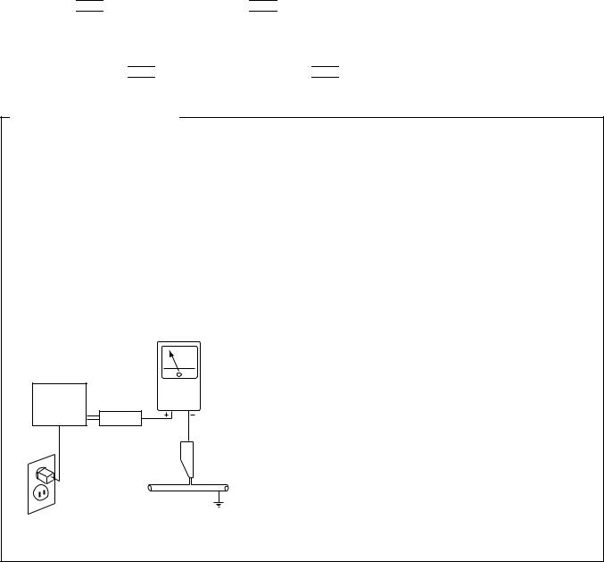
Measure leakage current to a known earth ground (water pipe, conduit, etc.) by connecting a leakage current tester such as Simpson Model 229-2 or equivalent between the earth ground and all exposed metal parts of the appliance (input/output terminals, screwheads, metal overlays, control shaft, etc.). Plug the AC line cord of the appliance directly into a 120V AC 60Hz outlet and turn the AC power switch on. Any current measured must not exceed 0.5mA.
|
|
Reading should |
|
Leakage |
not be above |
Device |
current |
0.5mA |
under |
tester |
|
test |
|
|
Test all |
|
|
exposed metal |
|
|
surfaces |
|
|
Also test with |
|
|
plug reversed |
|
Earth |
(Using AC adapter |
|
ground |
plug as required) |
|
|
AC Leakage Test
ANY MEASUREMENTS NOT WITHIN THE LIMITS OUTLINED ABOVE ARE INDICATIVE OF A POTENTIAL SHOCK HAZARD AND MUST BE CORRECTED BEFORE RETURNING THE APPLIANCE TO THE CUSTOMER.
2. PRODUCT SAFETY NOTICE
Many electrical and mechanical parts in the appliance have special safety related characteristics. These are often not evident from visual inspection nor the protection afforded by them necessarily can be obtained by using replacement components rated for voltage, wattage, etc. Replacement parts which have these special safety characteristics are identified in this Service Manual.
Electrical components having such features are identified by marking with a  on the schematics and on the parts list in this Service Manual.
The use of a substitute replacement component which does not have the same safety characteristics as the PIONEER recommended replacement one, shown in the parts list in this Service Manual, may create shock, fire, or other hazards.
Product Safety is continuously under review and new instructions are issued from time to time. For the latest information, always consult the current PIONEER Service Manual. A subscription to, or additional copies of, PIONEER Service Manual may be obtained at a nominal charge from PIONEER.
2
VSX-D508
2. EXPLODED VIEWS AND PARTS LIST
•
•The  mark found on some component parts indicates the importance of the safety factor of the part. Therefore, when replacing, be sure to use parts of identical designation.
•Screws adjacent to  mark on the product are used for disassembly.
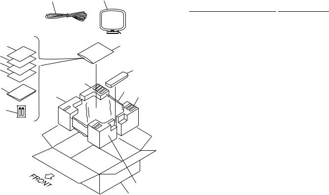
2.1PACKINGNOTES: Parts marked by "NSP" are generally unavailable because they are not in our Master Spare Parts List.
5 |
6 |
|
|
(1) PACKING PARTS LIST |
|
||
|
|
|
|
|
|
||
|
|
|
|
Mark |
No. |
Description |
Part No. |
|
|
|
|
|
1 |
Packing Sheet |
AHG7010 |
|
|
|
|
NSP |
2 |
Alkaline Dry Cell Battery |
VEM1012 |
|
|
|
|
|
|
(LR6, AA) |
|
|
|
|
|
|
3 |
Operating Instructions |
See Contrast table (2) |
7 |
|
10 |
|
|
4 |
Sub Instruction Manual |
ARH7039 |
|
|
|
|
(System Set up) |
|
||
|
|
|
|
|
|
|
|
6 |
|
|
|
|
5 |
FM Antenna |
ADH7004 |
5 |
|
|
|
|
|||
|
|
|
|
6 |
AMLoop Antenna |
ATB7009 |
|
4 |
|
|
8 |
|
|||
|
|
NSP |
7 |
Warranty Card |
See Contrast table (2) |
||
|
|
|
|
||||
|
12(1/2) |
|
|
|
8 |
Remote Control Unit |
AXD7178 |
3 |
|
|
|
|
(CU-VSX138) |
|
|
|
1 |
|
|
|
|
|
|
11(1/2) |
|
12(2/2) |
|
9 |
• • • • • |
|
|
|
|
|
|
||||
|
|
|
|
|
10 |
Polyethylene Bag |
Z21-038 |
2 |
|
|
|
|
|
(0.03×230×340) |
|
|
|
|
|
11 |
Front Pad 508 |
AHA7236 |
|
|
|
|
|
|
|||
|
|
|
|
|
12 |
Rear Pad 508 |
AHA7237 |
|
|
|
|
|
13 |
Packing Case 508UC |
AHD7643 |
11(2/2)
13
(2) CONTRAST TABLE
VSX-D508/KUXJI and KCXJI are constructed the same except for the following :
Mark |
No. |
Symbol and Description |
Part No. |
|
Remarks |
|
KUXJI Type |
|
KCXJI Type |
||||
|
|
|
|
|
||
|
3 |
Operating Instructions (English) |
ARB7157 |
|
Not used |
|
|
3 |
Operating Instructions (English/French) |
Not used |
|
ARE7179 |
|
NSP |
7 |
WarrantyCard |
ARY7023 |
|
ARY7024 |
|
|
|
|
|
|
|
|
3

VSX-D508
2.2 EXTERIOR
32 |
57 |
|
57 |
|
|
|
|
26 |
60 |
57 |
28 |
Note 1 : |
+ 2 |
kg • cm |
Torque is 12 – 0 |
||
8
7
55 10
 K
K
33
53
E
 L
L
6
57
49
42
 56
56
46
41

 J
J
55
18
57
44
50
|
(KCXJI |
|
|
11 |
|
|
|
Type |
|
1 |
4 |
|
|
Only) |
|
|
|
|
|
71 |
57 |
12 |
|
|
|
|
|
69 |
|
|
61 |
57 |
58 60 |
|
|
57 |
20 |
53 |
68 |
||
|
|
1 |
|
||
L |
K |
|
|
19 54 66 |
|
|
|
D |
|
57 |
|
|
|
|
|
35 |
|
|
|
|
|
|
|
|
|
|
|
65 |
64 |
|
I |
|
|
|
|
|
|
|
|
|
|
|
|
|
57 |
|
63 |
|
|
|
65 |
|
|
|
|
|
|
|
|
5 |
|
|
|
|
|
|
|
|
|
57 |
39 |
|
|
62 |
|
|
|
|
|
|
40 |
57 |
|
|
|
|
57 |
E |
|
|
|
|
57 |
|
|
21
 D 36
D 36
2
31
16
24
 F
F
29
57 57
57
 40 J
40 J
I 
38
3 |
57 |
25 |
37 |
39 |
|
C |
59 |
|
|||
|
59 |
|
A |
||
|
|
|
|
59 |
|
|
|
|
|
|
|
|
|
|
|
22 |
|
|
43 |
|
|
B Accessories of |
|
|
51 |
|
|
Front Panel 508 |
|
|
|
H 59 53 (No. 47) |
|
||
|
|
|
|
||
|
|
|
|
A |
|
|
|
|
9 |
|
|
|
47 |
57 |
|
|
|
|
57 |
|
|
|
|
52 |
57 |
|
|
|
|
|
|
|
|
|
57 |
|
|
|
|
57 |
57 |
|
|
|
|
|
57 |
|
|
|
|
57 |
|
23 |
|
|
|
|
G |
67 |
|
|
13 |
34 |
|
|
|
|
F |
|
|
|
|
|
|
27 |
17 |
|
|
|
|
|
|
C |
H |
|
|
|
|
|
|
|
|
G |
|
57 |
|
57 |
58 |
|
|
|
|
57 |
|
|
57 |
|
57 |
|
|
|
1 |
|
B |
|
|
|
|
|
|
|
30
57 70
4
VSX-D508
(1) EXTERIOR PARTS LIST
Mark |
No. |
Description |
|
Part No. |
Mark |
No. |
Description |
|
Part No. |
|
1 |
INPUT Assy |
|
AWX7207 |
|
36 |
Insulator |
|
PNW2766 |
|
2 |
FRONT Assy |
|
AWX7212 |
|
37 |
Locking Card Spacer |
|
AEC7160 |
NSP |
3 |
POWER SW Assy |
|
AWX7222 |
|
38 |
PCB Mold |
|
AMR2533 |
NSP |
4 |
REAR SP Assy |
|
AWX7250 |
NSP |
39 |
Card Spacer |
|
DEC1770 |
|
5 |
AMP Assy |
|
See Contrast table (2) |
NSP |
40 |
Binder |
|
RNE1277 |
NSP |
6 |
HEADPHONE Assy |
|
AWX7229 |
|
|
|
|
|
|
7 |
TRANS 1 Assy |
|
AWX7231 |
|
41 |
Volume Knob 508 |
|
AAB7179 |
|
8 |
TRANS 2 Assy |
|
AWX7232 |
|
42 |
Sub Panel 508 |
|
AAD7482 |
NSP |
9 |
FRONT VIDEO Assy |
|
AWX7239 |
|
43 |
Function Button |
|
AAD7483 |
|
10 |
BARRIER Assy |
|
AWX7284 |
|
44 |
Power Button |
|
AAD7440 |
NSP |
11 |
F.SP.CONNECT Assy |
|
AWX7285 |
|
45 |
• • • • • |
|
|
|
|
|
|
|
|
||||
NSP |
12 |
R.C.SP.CONNECT Assy |
|
AWX7286 |
|
46 |
Display Window R508 |
|
AAK7579 |
|
13 |
VIDEO Assy |
|
AWX7234 |
|
47 |
Front Panel 508 |
|
AMB7525 |
|
14 |
• • • • • |
|
|
|
48 |
• • • • • |
|
|
|
15 |
• • • • • |
|
|
|
49 |
Name Plate |
|
PAM1776 |
|
16 |
FRONT SP. Assy |
|
AWX7243 |
|
50 |
LED Lens |
|
PNW2019 |
|
|
|
|
|
|
|
|||
|
17 |
DOLBY DIGITAL Assy |
|
AWX7333 |
|
51 |
• • • • • |
|
|
|
18 |
Power Transformer (T1) |
|
See Contrast table (2) |
|
52 |
• • • • • |
|
|
|
19 |
Fuse (FU1 : 10A) |
|
REK1087 |
|
53 |
Screw |
|
ABA7009 |
|
20 |
Fuse (FU2 : 7A) |
|
VEK1027 |
|
54 |
Screw |
|
ABA7043 |
|
21 |
FFC 21P (J2) |
|
ADD7100 |
|
55 |
Screw |
|
ABA7044 |
|
|
|
|
|
|
|
|||
|
22 |
FFC 15P (J4) |
|
ADD7102 |
|
56 |
• • • • • |
|
|
|
23 |
FFC 13P (J5) |
|
ADD7103 |
|
57 |
Screw |
|
BBZ30P080FZK |
|
24 |
FFC 17P (J8) |
|
ADD7107 |
|
58 |
Screw |
|
BBZ30P200FMC |
|
25 |
FFC 26P (J3) |
|
ADD7118 |
|
59 |
Screw |
|
BPZ30P080FMC |
|
26 |
AC Power Cord |
|
ADG7024 |
|
60 |
Screw |
|
FBT40P080FZK |
|
|
|
|
|
|
|
|||
NSP |
27 |
8P Shield Cable (J6) |
|
ADX7242 |
NSP |
61 |
Binder (BK-1) |
|
ZCA-BK1 |
|
28 |
Cord Stopper |
|
CM-22C |
|
62 |
Heat Sink Angle F |
|
ANG7194 |
|
29 |
Tuner Holder B |
|
AAD7490 |
|
63 |
Heat Sink Angle R |
|
ANG7195 |
NSP |
30 |
Under Base D5 |
|
ANA7079 |
NSP |
64 |
Heat Sink D5 |
|
ANH7090 |
|
31 |
Rear Panel |
|
See Contrast table (2) |
|
65 |
Screw |
|
BBZ30P080FMC |
|
|
|
|
|
|
|
|||
|
32 |
Bonnet Case |
|
AZN7762 |
NSP |
66 |
FET Assy |
|
AWX7228 |
|
33 |
Trans Frame |
|
ANG7193 |
|
67 |
FM/AM TUNER Unit |
|
AXX7046 |
|
34 |
DSP Shield |
|
ANG7196 |
|
68 |
Sheet |
|
AEE7026 |
NSP |
35 |
Heat Sink Assy D5 |
|
ANH7095 |
|
69 |
FET Angle |
|
ANG7186 |
|
|
|
|
|
|
70 |
Foot Assy |
|
REC1263 |
|
|
|
|
|
|
71 |
Fuse (FU701 : 10A) |
|
See Contrast table (2) |
(2) CONTRAST TABLE
VSX-D508/KUXJI and KCXJI are constructed the same except for the following :
Mark |
No. |
Symbol and Description |
Part No. |
|
Remarks |
|
KUXJI Type |
|
KCXJI Type |
||||
|
|
|
|
|
||
|
5 |
AMP Assy |
AWX7223 |
|
AWX7331 |
|
|
18 |
Power Transformer (T1) |
ATS7234 |
|
ATS7235 |
|
|
31 |
Rear Panel 508U |
ANC7700 |
|
Not used |
|
|
31 |
Rear Panel 508C |
Not used |
|
ANC7751 |
|
|
71 |
Fuse (FU701 : 10A) |
Not used |
|
REK1087 |
|
|
|
|
|
|
|
|
5
|
1 |
|
2 |
|
3 |
|
4 |
|
|
|
|
|
|
VSX-D508
3. SCHEMATIC DIAGRAM
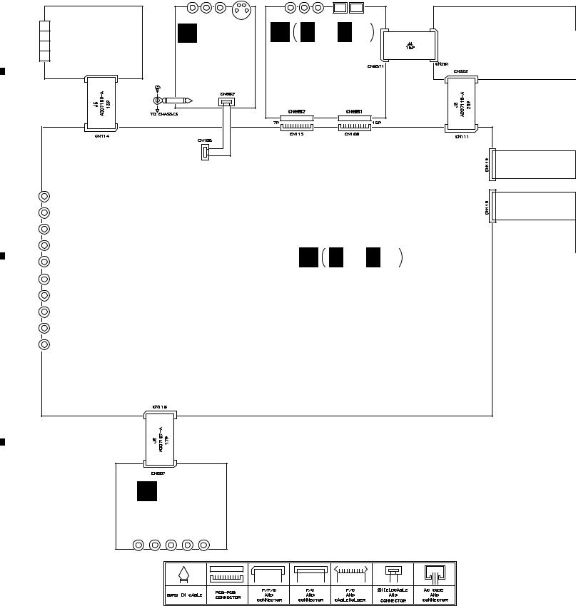
3.1 OVERALL WIRING CONNECTION DIAGRAM
A
FM/AM TUNER |
UNIT |
(AXX7046) |
O |
P P 1/3- P 3/3 |
|
FRONT VIDEO |
DOLBY DIGITAL |
|
ASSY |
||
ASSY |
||
(AWX7239) |
||
(AWX7333) |
||
|
B
A A 1/2, A 2/2
INPUT ASSY (AWX7207)
C
N
VIDEO ASSY
(AWX7234)
D
6
|
1 |
|
2 |
|
3 |
|
4 |
|
|
|
|
|
|
||||
|
|
|
|
|
|
5 |
|
6 |
|
7 |
|
8 |
|
|
|
|
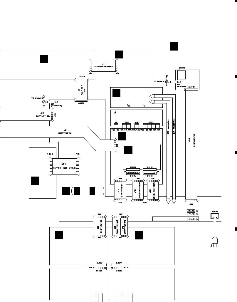
VSX-D508
Note : When ordering service parts, be sure to refer to "EXPLODED VIEWS and PARTS LIST" or "PCB PARTS LIST".
B
FRONT ASSY
(AWX7212)
C POWERASSY SW (AWX7222)
K TRANS 1 ASSY
(AWX7231)
POWER TRANSFORMER (T1) (KUXJI TYPE : ATS7234) (KCXJI TYPE : ATS7235)
I
HEADPHONE
ASSY
(AWX7229)
A
B
J |
TRANS 2 ASSY |
|
(AWX7232) |
|
L |
BARRIER ASSY |
|
(AWX7284) |
|
M |
|
FET ASSY |
D D 1/2, D 2/2 |
C |
(AWX7228) |
||
|
|
|
|
AMP ASSY |
|
|
(KUXJI TYPE : AWX7223) |
J52 J51 |
|
(KCXJI TYPE : AWX7331) |
FU1 REK1087 (10A) |
|
|
KCXJI FU2 VEK1027 (7A) |
|
|
TYPE |
|
|
ONLY FU701 REK1087 (10A) |
F |
E |
R.C.SP. |
F.SP. |
CONNECT ASSY |
CONNECT ASSY |
(AWX7286) |
(AWX7285) |
AC POWER CORD : ADG7024
AC120V
60Hz
D
H |
|
G |
|
REAR SP ASSY |
FRONT SP. ASSY |
||
(AWX7250) |
(AWX7243) |
||
7
|
5 |
|
6 |
|
7 |
|
8 |
|
|
|
|
|
|
||||
|
|
|
|
|
A
B
C
D
1 |
|
2 |
|
3 |
|
4 |
|
|
|
|
|
VSX-D508
3.2 INPUT ASSY (1/2)
A 1/2 |
INPUT ASSY(1/2) |
O CN602 |
|
||
|
(AWX7207) |
|
• FUNCTION BLOCK |
|
|
|
JA103 (1/2) |
AKB7113 |
|
|
|
JA102 (1/2) |
AKB7113 |
|
|
|
JA101 (1/2) |
AKB7113 |
|
|
|
JA101 (2/2) |
AKB7113 |
|
|
|
JA102 (2/2) |
AKB7113 |
|
|
|
|
|
|
TO |
|
|
|
|
FM/AM TUNER UNIT |
|
JA103 (2/2) |
AKB7113 |
|
|
|
|
|
|
A 2/2 |
|
A 1/2 |
D 1/2 |
406 |
|
8 |
|
B CN202 |
||
|
1 |
|
2 |
|
3 |
|
4 |
|
|
|
|
|
|
||||
|
|
|
|
|
|
5 |
|
6 |
|
7 |
|
8 |
|
|
|
|
|
|
VSX-D508
A 2/2
|
|
|
|
|
|
|
|
|
|
|
|
|
|
|
L ch |
: AUDIO SIGNAL ROUTE |
A |
||
|
|
|
|
|
|
|
|
|
|
|
|
|
|
|
C ch |
: AUDIO SIGNAL ROUTE (CENTER) |
|
||
|
|
|
|
|
|
|
|
|
|
|
|
|
|
|
|
|
|||
|
|
|
|
|
|
|
|
|
|
|
|
|
|
|
FL ch |
: AUDIO SIGNAL ROUTE (FRONT) |
|
||
|
|
|
|
|
|
|
|
|
|
|
|
|
|
|
|
|
|||
|
|
|
|
|
|
|
|
|
|
|
|
|
|
|
|
|
|
|
|
|
|
|
P 1/3 |
|
|
|
|
CN9801 |
|
|
|
|
|
B |
|
|
J 352 |
|
|
|
|
|
|
C |
|
|
|
N |
|
|
|
|
CN507 |
|
|
|
P 1/3 |
|
|
|
|
CN9802 |
|
|
|
|
|
|
D |
B CN202 |
|
|
A 1/2 |
9 |
|
|
|
|
|
5 |
6 |
7 |
8 |
|
|
1 |
|
2 |
|
3 |
|
4 |
|
|
|
|
|
|
A
B
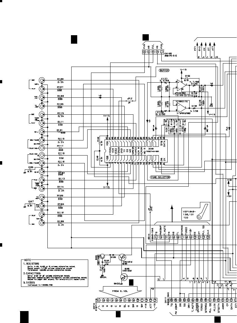
VSX-D508
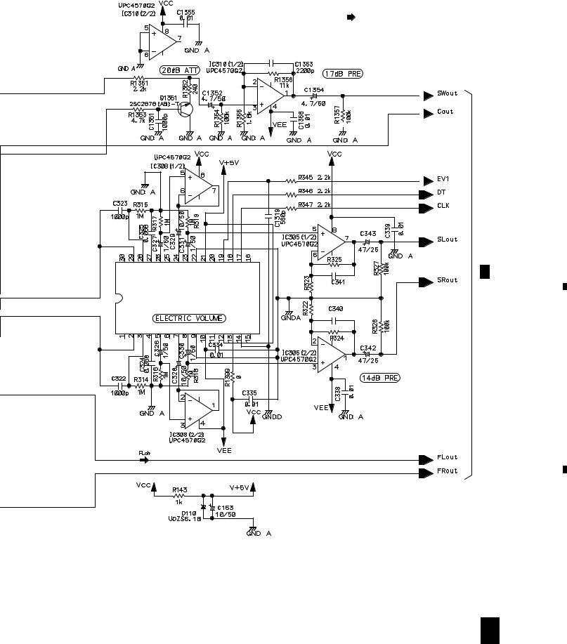
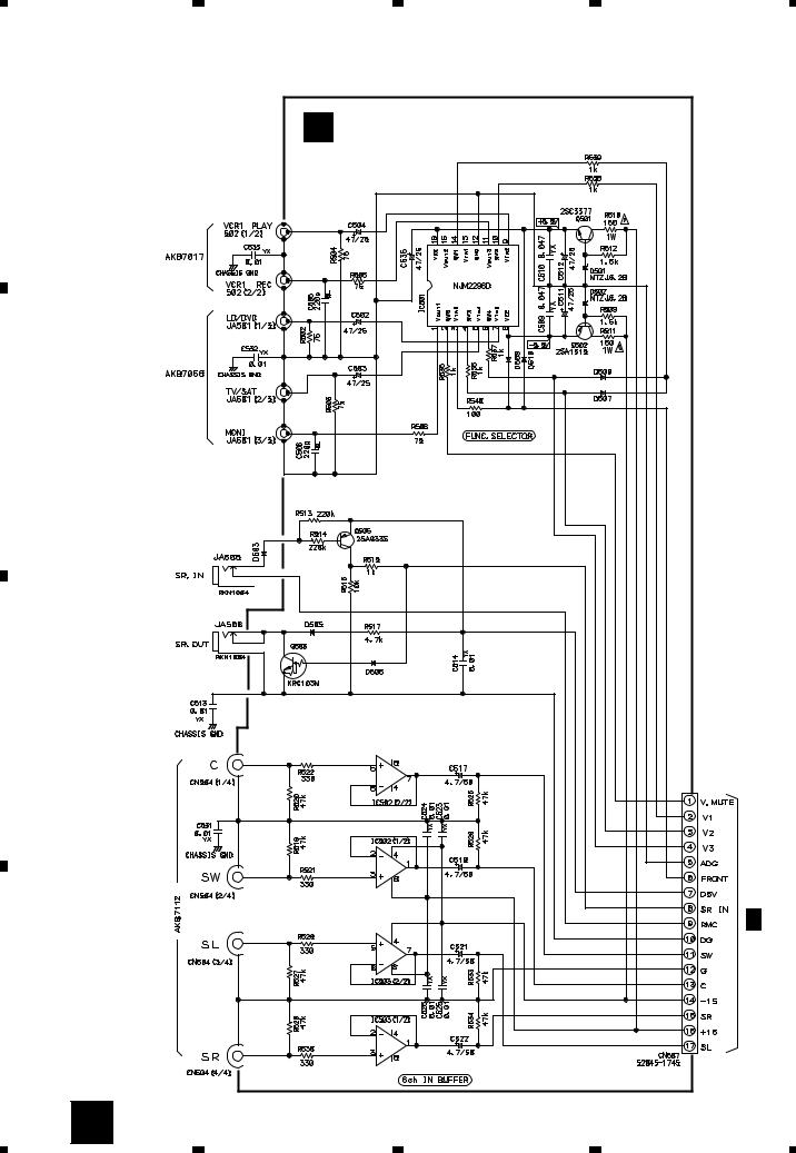
3.3 INPUT ASSY (2/2)
A 2/2 INPUT ASSY(2/2) (AWX7207)
• E. VOL BLOCK |
A 1/2 |
IC301 |
|
LC7535M |
|
(LC7536M) |
|
3k |
120p |
|
|
|
12k |
A 1/2
A 1/2
C |
|
|
|
|
12k |
IC303 |
3k |
68p |
LC7535M |
|
|
(LC7536M) |
|
|
|
3k |
68p |
|
|
|
|
|
12k |
D
10 A 2/2
|
1 |
|
2 |
|
3 |
|
4 |
|
|
|
|
|
|
||||
|
|
|
|
|
|
5 |
|
6 |
|
7 |
|
8 |
|
|
|
|
|
|
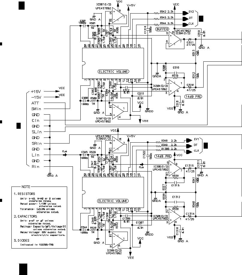
VSX-D508
FL ch |
: AUDIO SIGNAL ROUTE (FRONT) |
A |
||||
|
|
|
|
|||
|
|
|
|
|
|
|
|
|
|
|
|
|
|
|
|
|
|
|
|
|
|
|
|
|
|
|
|
|
|
|
|
|
|
|
|
|
|
|
|
|
|
|
|
|
|
|
|
|
|
|
|
|
|
|
|
|
|
|
|
|
|
|
|
|
|
B |
|
|
12k |
A 1/2 |
|
|
|
|
IC302 |
3k |
120p |
|
|
|
|
|
LC7535M |
|
|
|
(LC7536M) |
3k |
|
|
|
120p |
|
|
|
|
|
|
|
|
12k |
|
|
|
|
C |
D
A 2/2 11
|
5 |
|
6 |
|
7 |
|
8 |
|
|
|
|
|
|
||||
|
|
|
|
|
|
1 |
|
2 |
|
3 |
|
4 |
|
|
|
|
|
|
VSX-D508
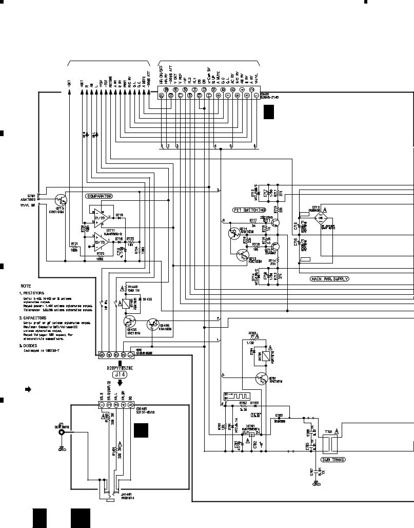
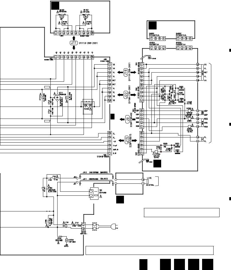
3.4 FRONT and POWER SW ASSEMBLIES
A |
A |
1/2 CN111 |
B FRONT ASSY (AWX7212)
B |
|
|
|
|
|
C |
|
MASTER VOLUME |
|
|
|
|
|
|
C |
POWER SW |
|
|
|
|
ASSY |
|
|
|
|
(AWX7222) |
|
|
|
|
P 2/3 |
|
|
|
|
CN9371 |
|
|
|
D |
|
|
|
|
12 |
B C |
|
|
|
|
1 |
2 |
3 |
4 |
|
5 |
|
6 |
|
7 |
|
8 |
|
|
|
|
VSX-D508
D 2/2 CN401
5 |
6 |
7 |
FRONT ASSY
S201 : MIDNIGHT
S202 : DSP MODE
S205 : –
S206 : + BASS
S207 : –
TREBLE
S208 : +
S209 : A
SPEAKERS
S210 : B
S211 : LOUDNESS
S212 : DIRECT
S213 :  (DOLBY)
S214 : SIGNAL SELECT
S217 : TV/SAT
S218 : VIDEO
S219 : CD
S220 : TUNER
S221 : VCR
S222 : DVD/LD
S223 : MD/TAPE
S224 : AUX
S229 : CLASS
S230 : MEMORY
S231 : MPX MODE
S233 : –
S234 : + CHANNEL LEVEL
S235 : CHANNEL SELECT
S250 : MASTER VOLUME
B 13
8
A
B
C
D

|
1 |
|
2 |
|
3 |
|
4 |
|
|
|
|
|
|
VSX-D508 |
|
|
|
3.5 AMP (1/2), F.SP.CONNECT, R.C.SP.CONNECT, FRONT SP. and REAR SP |
|||
ASSEMBLIES |
|
|
|
A |
|
|
|
|
4.7/50 |
|
|
|
4.7/50 |
|
|
B |
|
|
|
CN112 |
4.7/50 |
|
|
|
|
|
|
A 1/2 |
|
|
|
|
|
18p |
|
|
4.7/50 |
|
|
C |
|
|
|
|
4.7/50 |
|
|
D |
|
|
|
D 2/2 |
|
D 1/2 AMP ASSY(1/2) |
|
|
JA413 |
(KUXJI TYPE : AWX7223) |
|
|
AKB7111 |
(KCXJI TYPE : AWX7331) |
D 2/2 |
|
|
||
14 D 1/2
|
1 |
|
2 |
|
3 |
|
4 |
|
|
|
|
|
|
||||
|
|
|
|
|
5 |
6 |
|
D 2/2 |
|
0.1 |
|
0.1 |
D 2/2 |
|
5 |
6 |
|
7 |
|
8 |
|
|
|
|
VSX-D508
FL ch |
: AUDIO SIGNAL ROUTE (FRONT) |
A |
|
|
E F.SP. CONNECT ASSY |
|
|
(AWX7285) |
|
|
G FRONT SP. ASSY |
|
|
(AWX7243) |
|
|
0.1 |
0.1 |
|
|
AKE7006 |
|
|
|
|
|
|
B |
|
|
JA653 |
|
22k |
AKB7111 |
|
|
|
|
1.2k |
|
|
|
C |
|
0.1 |
|
|
|
AKE7041 |
H REAR SP ASSY (AWX7250)
F R.C.SP. CONNECT ASSY (AWX7286)
D
CAUTION : FOR CONTINUED PROTECTION AGAINST RISK OF FIRE, REPLACE ONLY WITH SAME TYPE NO. ICP-N25, MFD BY ROHM CO., LTD. FOR IC404 and IC405.
|
|
D |
1/2 |
E |
|
F |
|
G |
|
H |
15 |
|
||
|
|
|
7 |
|
|
|
|
|
|
|
|
8 |
|
|
|
|
|
||||||||||||
|
|
|
||||||||||||
1  2
2  3
3  4
4
VSX-D508
3.6 AMP (2/2), HEADPHONE, TRANS 2, TRANS 1, BARRIER and FET ASSEMBLIES 

A
D 2/2
AMP ASSY(2/2)
(KUXJI TYPE : AWX7223)
(KCXJI TYPE : AWX7331)
B
+43.1
–43.1
C
HP
: AUDIO SIGNAL ROUTE (HEAD PHONE)
D
I
HEADPHONE ASSY
(AWX7229)
ATT1223 1000/25 


16 D 2/2 I
|
1 |
|
2 |
|
3 |
|
4 |
|
|
|
|
|
|
||||
|
|
|
|
|
|
5 |
|
6 |
|
7 |
|
8 |
|
|
|
|
|
|
VSX-D508
M FET ASSY (AWX7228)
A
L BARRIER ASSY (AWX7284)
+66.1 |
|
|
B |
|
KUXJI |
|
TRANS. |
|
TYPE |
|
|
|
|
NP |
|
REK1087 KCXJI |
|
MAIN |
|
10A |
A 1/2 |
|
|
TYPE |
|
|
|
–66.1 |
CN115 |
|
|
|
|
|
|
|
J |
TRANS 2 ASSY |
C |
|
|
|
|
|
|
(AWX7232) |
|
VEK1027
7A
MAIN TRANS.
AC OUTLET |
K TRANS 1 ASSY |
|
(AWX7231) |
REK1087
10A
ATF7018
|
CAUTION : FOR CONTINUED PROTECTION AGAINST RISK OF FIRE, |
|
REPLACE ONLY WITH SAME TYPE NO. ICP-N70, MFD BY |
|
ROHM CO., LTD. FOR IC351 - IC354. |
LIVE |
|
AC120V |
|
60Hz |
|
NEUTRAL AC POWER CORD |
|
ADG7024 |
D |
• NOTE FOR FUSE REPLACEMENT
CAUTION -FOR CONTINUED PROTECTION AGAINST RISK OF FIRE. REPLACE WITH SAME TYPE AND RATINGS ONLY.
D 2/2 J 
 K
K 
 L
L 
 M 17
M 17
|
5 |
|
6 |
|
7 |
|
8 |
|
|
|
|
|
|
||||
|
|
|
|
|
|
1 |
2 |
3 |
4 |
VSX-D508 |
|
|
|
|
3.7 VIDEO ASSY |
|
N VIDEO ASSY |
|
|
|
|
|
|
|
A |
|
|
(AWX7234) |
|
B |
|
|
|
|
C |
|
|
|
|
|
|
|
NJM4558D-D |
|
|
|
|
NJM4558D-D |
|
|
|
|
|
A 1/2 |
|
|
|
|
CN110 |
|
|
|
NJM4558D-D |
|
D |
|
|
NJM4558D-D |
|
18 |
N |
|
|
|
|
1 |
2 |
3 |
4 |
|
1 |
|
2 |
|
3 |
|
4 |
|
|
|
|
|
|
VSX-D508
3.8 FRONT VIDEO ASSY
A
CN601 AKB7085
O FRONT VIDEO ASSY (AWX7239)
PCB BINDER 601 VEF1040
Y20 ADX7248
A 1/2
CN105
B
C
D
O 19
|
1 |
|
2 |
|
3 |
|
4 |
|
|
|
|
|
|
||||
|
|
|
|
|
 Loading...