


VSX-921
Table of contents
 Loading...
Operating Instructions
– Advanced MCACC PC Display Application Software –
audio/video multi-channel receiver
2
About this manual
These are the Operating Instructions for an application which displays on your computer screen the
listening room reverberation frequency characteristics, the speakers’ group delay characteristics and the
MCACC parameters measured by the Advanced MCACC function of your receiver.
It explains everything you need to know to use the application, from loading measurement data to
displaying measurement results and troubleshooting. You will need to operate the receiver to use this
application, so please refer also to the Operating Instructions supplied with the receiver.
Important
The explanations concerning the “Group Delay” functions (“group delay characteristics of the
speakers”, etc.) included in these operating instructions only apply for receivers supporting the Full
Band Phase Control function.
About the Advanced MCACC Application
The functions of the Advanced MCACC application are used with the same purpose as the “Reverb View”
and “Group Delay” functions of the receiver itself (see the receiver’s Operating Instructions), namely to
display the reverberation characteristics of the listening environment and the group delay characteristics of
the speakers. Using a computer provides cleaner, more easily readable graphs. The application can also be
used to display the measurement values stored in the receiver’s MCACC memory.
Requirements for using the application on your PC
• The computer must be a PC functioning with one of the following operating systems: Microsoft
®
Windows
®
7 Home Premium/Ultimate/Professional, Windows
®
Vista Home Basic/Home Premium/
Ultimate SP2 or Windows
®
XP Professional/Home Edition SP3.
• The monitor must have a display resolution of 1024 x 768 dots (XGA) or greater.
• That the receiver and computer are connected to the network via LAN.
Microsoft
®
, Windows
®
7, Windows
®
Vista and Windows
®
XP are either registered trademarks or trademarks of
Microsoft Corporation in the United States and/or other countries.
Main features of the application
1. Displays 3D graphs of the reverberation frequency characteristics of your room. You can choose to
see these measurements both with and without the equalization performed by this receiver (before
and after calibration).
2. Allows you to display 3D graphics of the group delay characteristics of the different speakers. (The
values before and after calibration can be displayed.)
3. Allows you to display a list of the Advanced MCACC parameters (the results of measurements).
4. Allows you to view graphs in a number of different formats.
5. Allows you to save the various measured data on the computer.
6. Allows you to make memos about the conditions in your room when you made the measurements,
etc.
7. Allows you to print the various graphs and the MCACC measurement values.
Continue

3
About the Advanced MCACC Application (Continued)
Things you can accomplish with this application
1. Advanced EQ Setup, which you can do with the receiver (see the receiver’s Operating Instructions),
allows you to choose the optimum time period for auto EQ setup. You can use this application’s
reverberation characteristics (Reverb) as a guide in choosing the best time period for your room.
For details, see Deciding the time period for Advanced EQ Setup calibration
(page 15).
2. Skewed reverb frequency characteristics in your listening room can prevent you from enjoying an
accurate sound field. The graphs displayed by this application are a powerful tool because they
allow you to check these reverb frequency characteristics at a glance. You can also check the
effectiveness of steps that you take to improve the acoustics of your listening room, for example,
installing sound absorbent material.
For details, see Checking steps to improve your room’s reverb characteristics
(page 17).
3. The reverb characteristics after calibration can be displayed. This lets you to check the EQ effects of
the Advanced MCACC measurements you have made.
For details, see About the display of the reverb characteristics graphs before and after calibration
(page 19).
4. The Group Delay graphs allow you to check the group delay characteristics before and after
calibration.
For details, see Reading the group delay characteristics graph (Group Delay)
(page 21).
5. The MCACC parameter display (Parameters) allows you to display on the computer all the
parameters (measurement values) stored in the receiver’s MCACC memories.
For details, see Display of the MCACC parameters
(page 22).

4
Transferring measurement data from the receiver to the
computer
To display on the computer the various data measured on the receiver, use AVNavigator to transfer the data
from the receiver to the computer.
If MCACC Application is launched automatically after the “Full Auto MCACC” operation has been performed
with AVNavigator’s “Wiring Navi” and measurements have been taken, the measurement data has already
been transferred to the computer. To recheck the measurement data in this case, proceed to the next
section, Applications Operations
(page 6).
If “Wiring Navi” has not been performed and you want to transfer the data measured under an environment
different from that of “Wiring Navi” to the computer, use the procedure described below.
1 Perform the “Full Auto MCACC” operation on the receiver. (See the receiver’s
Operating Instructions.)
2 After the “Full Auto MCACC” operation is completed, press the “HOME MENU”
button to close the home menu.
The measurement data is prepared to be sent at the point that the home menu is closed.
3 Launch AVNavigator on the computer.
4
From the AVNavigator menu, select “Settings”, then select the “MCACC Data” tab.
5 Specify the “MCACC Data Storage Folder”.
The measurement is saved in the folder specified here. The folder in which the data is saved can be
changed by pressing “Change”.
6
From the AVNavigator menu, select “MCACC Appli” to launch MCACC Application.
When the MCACC application is launched, the “MCACC data” screen appears simultaneously.
7 Follow the instructions on the “MCACC data” screen to download the data
measured in step 1.
The data measured in step 1 is transferred to the folder specified in step 4.
Proceed to Applications Operations
(page 6) and call out the measurement data from the computer.
Continue

5
Transferring measurement data from the receiver to the computer (Continued)
• Do not quit AVNavigator or turn off the receiver’s power until data transmission is completed.
• Transmission of measurement data from the receiver to the computer is performed each time MCACC
Application is launched with the receiver’s power turned on. The measurement data is overwritten
unless the “MCACC Data Storage Folder” is changed, so if you do not wish to overwrite the
measurement data, change the storage folder at "MCACC Data" under “Settings” before launching
MCACC Application.
• The graphs for both before calibration (“Before”) and after calibration (“After”) can be displayed on the
screen displaying the reverberation characteristics graphs after Full Auto MCACC measurements
(“Reverb”), but note that the graph displayed for the characteristics after calibration is a prediction of
the reverberation characteristics after Full Auto MCACC with the EQ Type : SYMMETRY.
For details, see About the display of the reverb characteristics graphs before and after calibration
(page 19).
If you want to check the graph of the actually measured reverberation characteristics after MCACC
calibration (not the prediction), measure the reverb characteristics again after calibration.
For details, see Displaying the reverb characteristics after EQ calibration (actually measured values)
(page 20).
• If calibration is performed with the Full Auto MCACC’s EQ Type set to anything other than SYMMETRY
(to either ALL CH ADJ or FRONT ALIGN), the reverberation characteristics after calibration cannot be
predicted, so the graph for the characteristics after calibration (“After”) cannot be displayed. In this
case, the graph for the characteristics after calibration can be displayed by measuring the
reverberation characteristics again with the same EQ Type as the type used for calibration. For details,
see Displaying the reverb characteristics after EQ calibration (actually measured values)
(page 20).
Note
6
Applications Operations
This section explains operations from calling out the measurement stored on the computer to displaying
graphs and storing data. Launch MCACC Application before performing the operations below.
Opening measurement data
1 Select “Open” under “File” on the menu bar.
2 Select the “.mcacc” file stored on the computer, then select “Open”.
The measurement data is displayed.
The “.mcacc” file is stored in the folder specified at “MCACC Data” under the AVNavigator's “Settings”
menu.
• The data used to display the reverberation characteristics graph (Reverb), the group delay characteristics
graph (Group Delay) and the MCACC parameters are not deleted even when the receiver’s power is
turned off. However, for the data used to display the reverberation characteristics graph (Reverb) and the
group delay characteristics graph the data stored in the receiver is overwritten when the reverberations
are measured again. If you wish to display graphs of various sets of data, perform the operation in
AVNavigator to transfer the measurement data to the computer each time measurements are made. For
details, see Transferring measurement data from the receiver to the computer
(page 4).
Note
Continue
7
Application Operations (Continued)
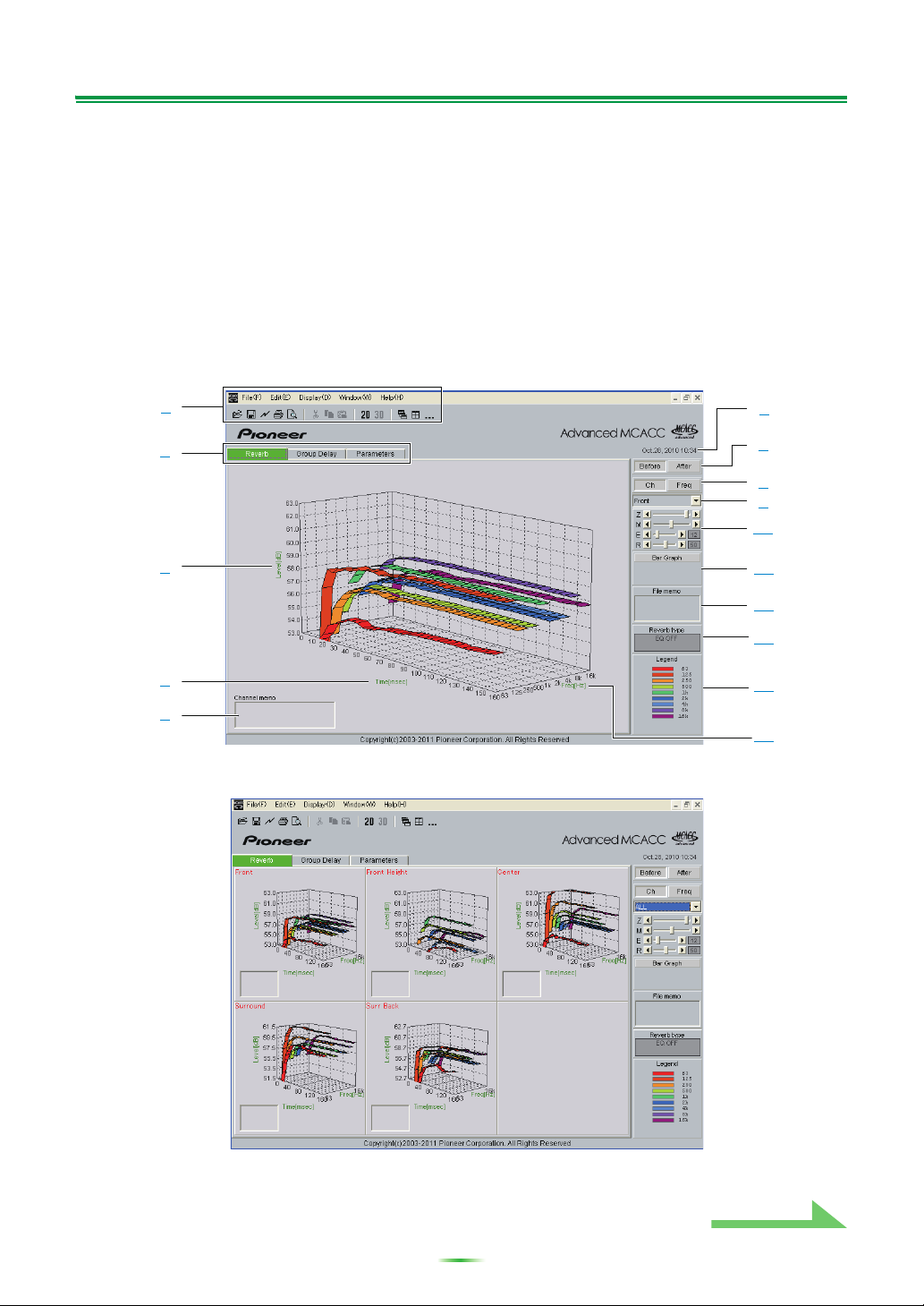
Graph and parameter displays (names and functions of parts)
When measurement data is received, the graphs and parameters display window appears. The display
window is divided into three items, “Reverb”, “Group Delay” and “Parameters”. Select the desired tab to
switch to that window and display the respective details.
Reverb (graph of the room’s reverberation frequency characteristics)
The display can be switched between the reverb characteristics graphs before and after calibration. You
can switch the display between individual displays for the different channels/frequencies or a list display of
all the channels/frequencies (ALL). Below we explain the different parts of the individual displays and the
ALL display, using the channel display as an example.
Individual display (Example: Front channel)
ALL display
1
2
3
4
5
6
7
8
9
10
11
12
13
14
15
Continue
8
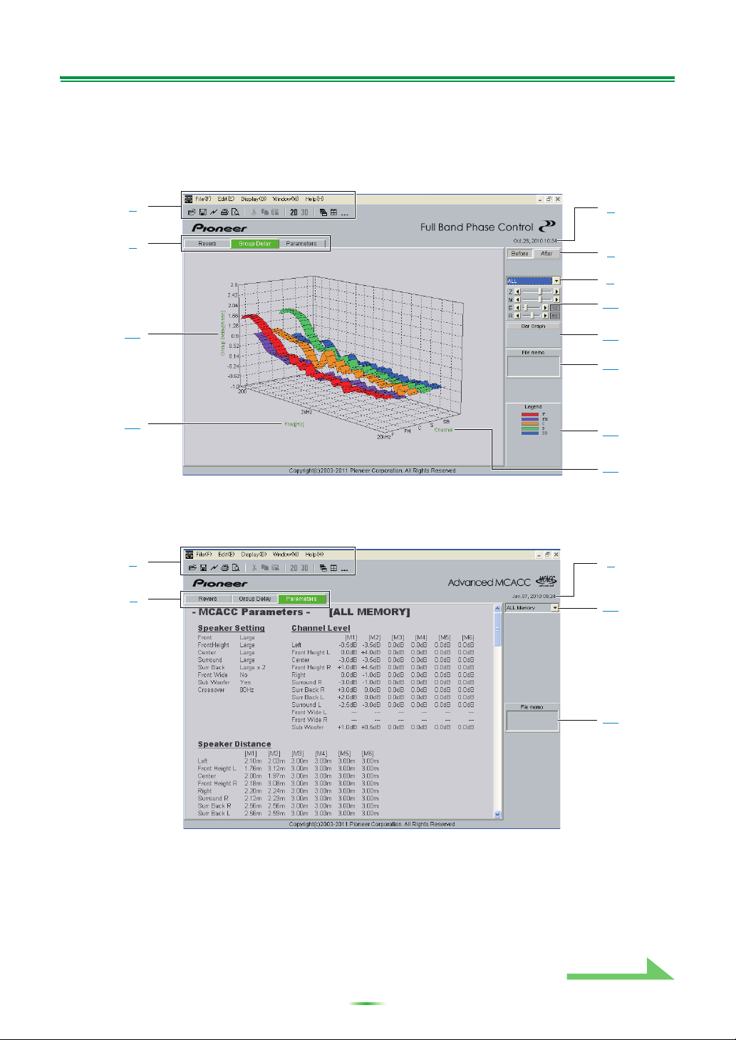
Application Operations (Continued)
Group Delay (graph of the speaker’s group delay characteristics)
You can switch the display between the speaker’s group delay characteristics before calibration and the
speaker’s group delay characteristics after calibration. You can also switch between the group delay
characteristics for all channels and the group delay characteristics for individual channels.
These graphs are only displayed for receivers supporting the Full Band Phase Control function.
MCACC Parameters (list display of MCACC parameters)
A list of the measurements in all the MCACC memories is displayed. It is also possible to display the
measurements in the individual MCACC memories.
(Depending on the model, the values at “Speaker Distance” may be displayed in feet (ft).)
1
2
6
7
12
16
17
9
10
14
11
18
1
2
6
19
12
Continue
9
Application Operations (Continued)
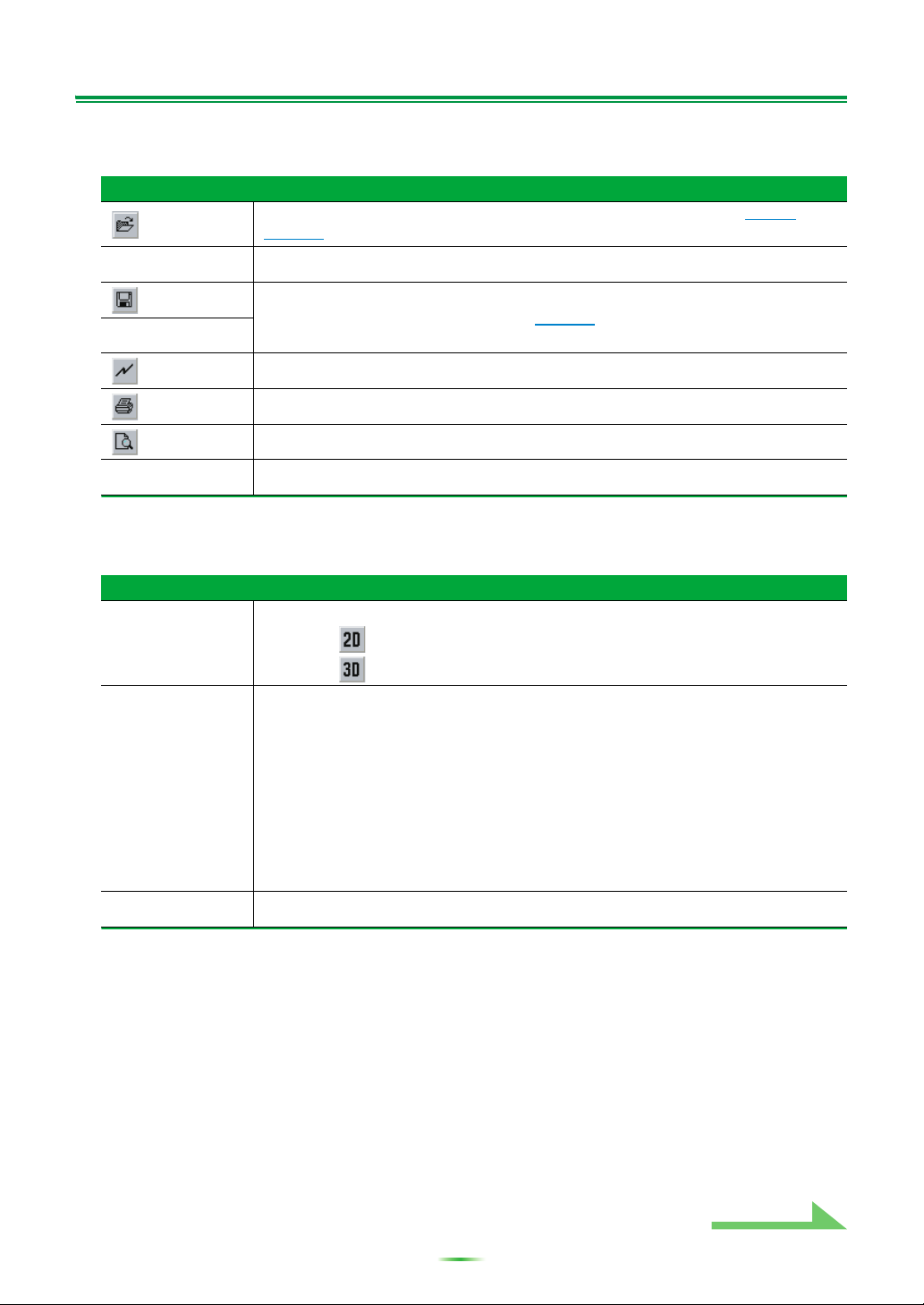
1 Menu bar and menu icons
You can choose the following commands from the application menus.
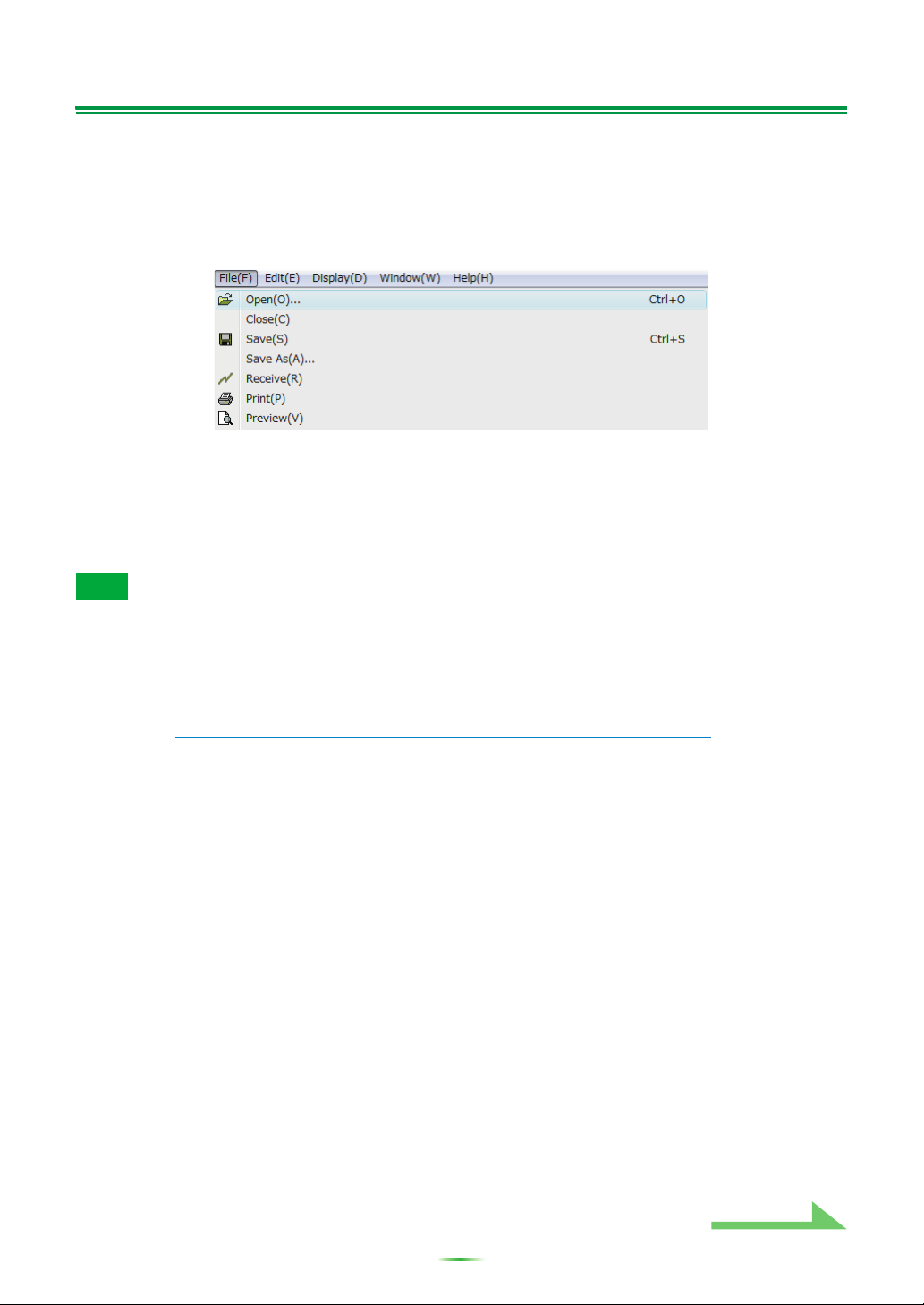
File
Open
Calls out measurement data and files stored on the computer. (see page 6 and
page 13).
Close
Closes a file.
Save
Save measurement data in a file (see page 12).
a
a. Choose “Save As” if you wish to save already saved data with a different name.
Save As
Receive
With this application, “Receive” cannot be used.
Print
Prints the current individual graph.
b
b. It is not possible to print or preview items that have not been received (items for which there is no
data).
Preview
Displays a preview screen to show how the printed page will appear.
b
Exit
Exits the application.
Display
Graph
The way in which the graphs are displayed can be changed.
Graph 2D : Displayed in two dimensions.
Graph 3D : Displayed in three dimensions.
Ty pe
(Reverb display
only)
The reverb characteristics graph display type can be changed.
Each Ch:
All the channels are displayed individually.
The “Each Ch” display type is set when EQ calibration is performed with the
reverberation type set to “ALL CH ADJ”.
Pair Ch:
Composite reverb characteristics for the left and right pairs of the “Front”,
“Surround” and “Surr Back” channels are displayed. The “Pair Ch” display type
is set when EQ calibration is performed with the reverberation type set to
“SYMMETRY” or “FRONT ALIGN”.
Demo
Displays 3D graphs with rotating.
a
a. To finish, reselect and uncheck the box.
Continue
Loading...