


VSX-D498
ORDER NO.
PIONEER ELECTRONIC CORPORATION 4-1, Meguro 1-Chome, Meguro-ku, Tokyo 153-8654, Japan
PIONEER ELECTRONICS SERVICE, INC. P.O. Box 1760, Long Beach, CA 90801-1760, U.S.A.
PIONEER ELECTRONIC (EUROPE) N.V. Haven 1087, Keetberglaan 1, 9120 Melsele, Belgium
PIONEER ELECTRONICS ASIACENTRE PTE. LTD. 253 Alexandra Road, #04-01, Singapore 159936
PIONEER ELECTRONIC CORPORATION 1999
c
VSX-D498
RRV2130
T – ZZE APR. 1999 Printed in Japan
AUDIO/VIDEO MULTI-CHANNEL RECEIVER
÷ Refer to the service manual RRV2086 for VSX-D508/KUXJI
and VSX-D508/KCXJI.
Remarks
Type
Model
VSX-D498
Power Requirement
THIS MANUAL IS APPLICABLE TO THE FOLLOWING MODEL(S) AND TYPE(S).
KUXJI ‡ AC120V
KCXJI ‡ AC120V
VSX-D498
2
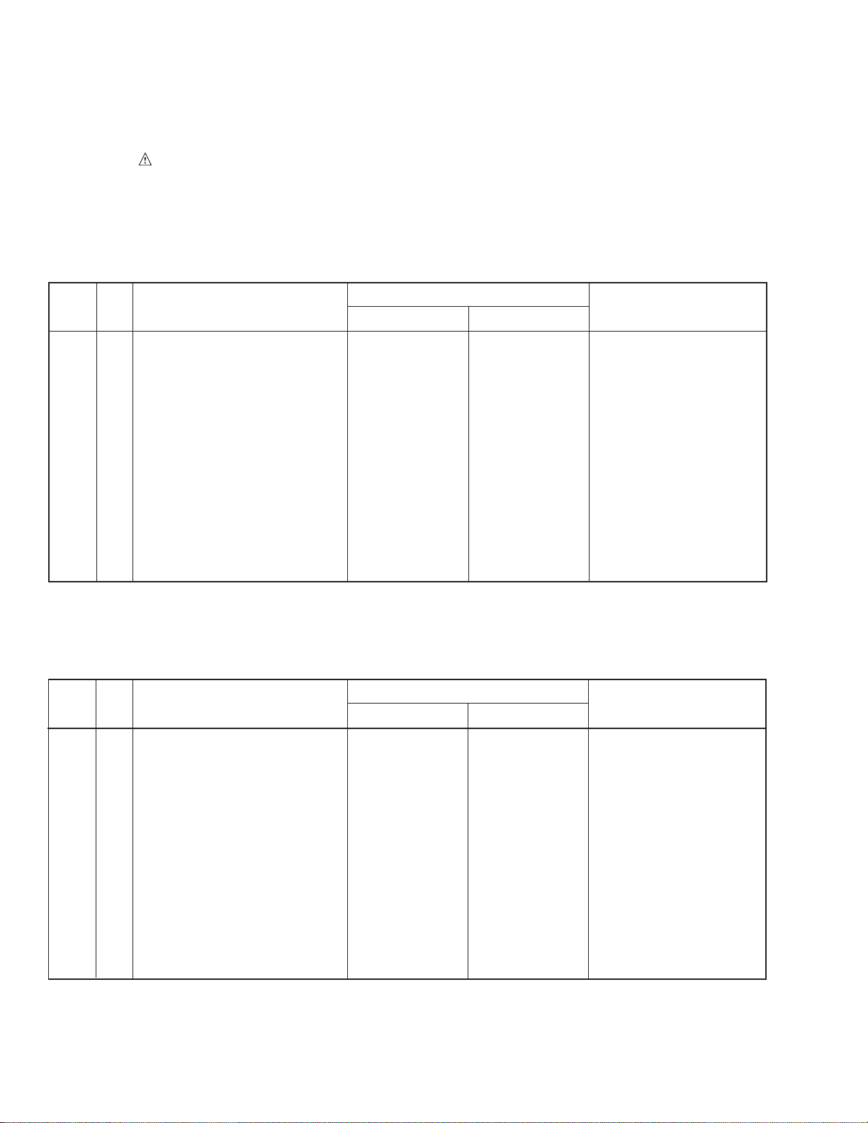
1. CONTRAST OF MISCELLANEOUS PARTS
NOTES : ÷ Parts marked by “ NSP ” are generally unavailable because they are not in our Master Spare Parts List.
÷ The
mark found on some component parts indicates the importance of the safety factor of the part.
Therefore, when replacing, be sure to use parts of identical designation.
÷ Screw adjacent to
∞
mark on the product are used for disassembly.
÷ Reference Nos. indicate the pages and Nos. in the service manual for the base model.
PACKING
P3 - 2 NSP Dry Cell Battery (LR6, AA) VEM1012 Not used
P3 - 2 NSP Dry Cell Battery (R6P, AA) Not used VEM-013
P3 - 3 Operating Instructions (English) ARB7157 ARB7192
P3 - 4 Sub Instruction Manual(System Set up) ARH7039 Not used
P3 - 8 Remote Control Unit (CU-VSX138) AXD7178 Not used
P3 - 8 Remote Control Unit (CU-VSX157) Not used AXD7226
P3 -13 Packing Case AHD7643 AHD7758
Battery Cover Not used RZN1156 for Remote Control Unit
(CU-VSX157)
EXTERIOR SECTION
P5 -31 Rear Panel ANC7700 ANC7837
P5 -47 Front Panel AMB7525 AMB7634
Ref.
No.
Remarks
VSX-D508/KUXJI VSX-D498/KUXJI
Part No.
Mark Symbol and Description
7 CONTRAST TABLE for VSX-D498/KUXJI
VSX-D498/KUXJI and VSX-D508/KUXJI are constructed the same except for the following:
PACKING
P3 - 2 NSP Dry Cell Battery (LR6, AA) VEM1012 Not used
P3 - 2 NSP Dry Cell Battery (R6P, AA) Not used VEM-013
P3 - 3 Operating Instructions (English/French) ARE7179 ARE7223
P3 - 4 Sub Instruction Manual(System Set up) ARH7039 Not used
P3 - 8 Remote Control Unit (CU-VSX138) AXD7178 Not used
P3 - 8 Remote Control Unit (CU-VSX157) Not used AXD7226
P3 -13 Packing Case AHD7643 AHD7758
Battery Cover Not used RZN1156 for Remote Control Unit
(CU-VSX157)
EXTERIOR SECTION
P5 -31 Rear Panel ANC7751 ANC7852
P5 -47 Front Panel AMB7525 AMB7634
Ref.
No.
Remarks
VSX-D508/KCXJI VSX-D498/KCXJI
Part No.
Mark Symbol and Description
7 CONTRAST TABLE for VSX-D498/KCXJI
VSX-D498/KCXJI and VSX-D508/KCXJI are constructed the same except for the following:
ORDER NO.
PIONEER ELECTRONIC CORPORATION 4-1, Meguro 1-Chome, Meguro-ku, Tokyo 153-8654, Japan
PIONEER ELECTRONICS SERVICE, INC. P.O. Box 1760, Long Beach, CA 90801-1760, U.S.A.
PIONEER ELECTRONIC (EUROPE) N.V. Haven 1087, Keetberglaan 1, 9120 Melsele, Belgium
PIONEER ELECTRONICS ASIACENTRE PTE. LTD. 253 Alexandra Road, #04-01, Singapore 159936
PIONEER ELECTRONIC CORPORATION 1999
c
VSX-D508
RRV2086
1. SAFETY INFORMATION
......................................
2
2. EXPLODED VIEWS AND PARTS LIST
................
3
3. SCHEMATIC DIAGRAM
.......................................
6
4. PCB CONNECTION DIAGRAM
..........................
26
5. PCB PARTS LIST
...............................................
39
6. ADJUSTMENT
....................................................
47
CONTENTS
7. GENERAL INFORMATION
................................
48
7.1 PARTS
..........................................................
48
7.1.1 IC
...........................................................
48
7.1.2 DISPLAY
................................................
51
7.2 DISASSEMBLY
............................................
53
7.3 BLOCK DIAGRAM
........................................
55
7.4 REMOTE CONTROL UNIT
..........................
56
[CU-VSX138 (AXD7178)]
8. PANEL FACILITIES AND SPECIFICATIONS
....
60
T – IZK JAN. 1999 Printed in Japan
Type
Model
Power Requirement Remarks
VSX-D508
KUXJI AC120V
KCXJI AC120V
THIS MANUAL IS APPLICABLE TO THE FOLLOWING MODEL(S) AND TYPE(S).
AUDIO/VIDEO MULTI-CHANNEL RECEIVER
STANDBY/ON
STANDBY
PHONES
AUDIO/VIDEO MULTI-CHANNEL RECEIVER
VSX-D508
STATION
TUNING
SELECT
SIGNAL
SELECT
MIDNIGHT
DOWN UP
BASS TREBLE
VCR DVD/LD TV/SAT VIDEO
CD
FM/AM MD/TAPE 1
B
LOUDNESS
TAPE 2
MONITOR
DIRECT
VIDEO
VIDEO
INPUT
L
MASTER
VOLUME
CLASS MEMORY
MPX
MODE
+
+
–
+
–
+
–
–
FREQUENCY
DSP
MODE
AUDIO
R
A
SPEAKERS
DVD 5.1CH
2
VSX-D508
1. SAFETY INFORMATION
This service manual is intended for qualified service technicians ; it is not meant for the casual do-it-
yourselfer. Qualified technicians have the necessary test equipment and tools, and have been trained
to properly and safely repair complex products such as those covered by this manual.
Improperly performed repairs can adversely affect the safety and reliability of the product and may
void the warranty. If you are not qualified to perform the repair of this product properly and safely, you
should not risk trying to do so and refer the repair to a qualified service technician.
WARNING
This product contains lead in solder and certain electrical parts contain chemicals which are known to the state of California to cause
cancer, birth defects or other reproductive harm.
Health & Safety Code Section 25249.6 – Proposition 65
NOTICE
(FOR CANADIAN MODEL ONLY)
Fuse symbols (fast operating fuse) and/or (slow operating fuse) on PCB indicate that replacement parts must
be of identical designation.
REMARQUE
(POUR MODÈLE CANADIEN SEULEMENT)
Les symboles de fusible (fusible de type rapide) et/ou (fusible de type lent) sur CCI indiquent que les pièces
de remplacement doivent avoir la même désignation.
ANY MEASUREMENTS NOT WITHIN THE LIMITS
OUTLINED ABOVE ARE INDICATIVE OF A POTENTIAL
SHOCK HAZARD AND MUST BE CORRECTED BEFORE
RETURNING THE APPLIANCE TO THE CUSTOMER.
2. PRODUCT SAFETY NOTICE
Many electrical and mechanical parts in the appliance
have special safety related characteristics. These are
often not evident from visual inspection nor the protection
afforded by them necessarily can be obtained by using
replacement components rated for voltage, wattage, etc.
Replacement parts which have these special safety
characteristics are identified in this Service Manual.
Electrical components having such features are identified
by marking with a
on the schematics and on the parts list
in this Service Manual.
The use of a substitute replacement component which does
not have the same safety characteristics as the PIONEER
recommended replacement one, shown in the parts list in
this Service Manual, may create shock, fire, or other hazards.
Product Safety is continuously under review and new
instructions are issued from time to time. For the latest
information, always consult the current PIONEER Service
Manual. A subscription to, or additional copies of, PIONEER
Service Manual may be obtained at a nominal charge from
PIONEER.
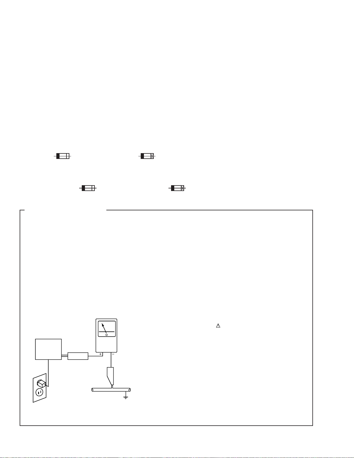
1. SAFETY PRECAUTIONS
The following check should be performed for the
continued protection of the customer and service
technician.
LEAKAGE CURRENT CHECK
Measure leakage current to a known earth ground (water
pipe, conduit, etc.) by connecting a leakage current tester
such as Simpson Model 229-2 or equivalent between the
earth ground and all exposed metal parts of the appliance
(input/output terminals, screwheads, metal overlays, control
shaft, etc.). Plug the AC line cord of the appliance directly
into a 120V AC 60Hz outlet and turn the AC power switch
on. Any current measured must not exceed 0.5mA.
(FOR USA MODEL ONLY)
Leakage
current
tester
Reading should
not be above
0.5mA
Device
under
test
Test all
exposed metal
surfaces
Also test with
plug reversed
(Using AC adapter
plug as required)
Earth
ground
AC Leakage Test
3
VSX-D508
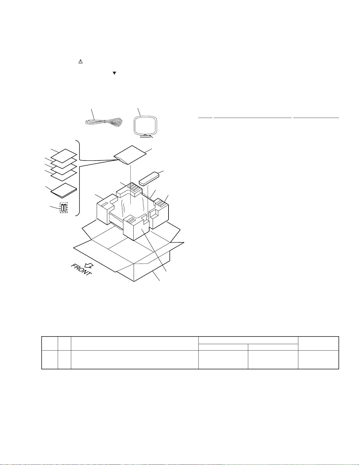
2.1 PACKING
(1) PACKING PARTS LIST
Mark No. Description Part No.
2. EXPLODED VIEWS AND PARTS LIST
NOTES:
•
Parts marked by "NSP" are generally unavailable because they are not in our Master Spare Parts List.
•
The mark found on some component parts indicates the importance of the safety factor of the part.
Therefore, when replacing, be sure to use parts of identical designation.
•
Screws adjacent to mark on the product are used for disassembly.
1 Packing Sheet AHG7010
NSP 2 Alkaline Dry Cell Battery VEM1012
(LR6, AA)
3 Operating Instructions See Contrast table (2)
4 Sub Instruction Manual ARH7039
(System Set up)
5 FM Antenna ADH7004
6 AMLoop Antenna ATB7009
NSP 7 Warranty Card See Contrast table (2)
8 Remote Control Unit AXD7178
(CU-VSX138)
9 • • • • •
10 Polyethylene Bag Z21-038
(0.03×230×340)
11 Front Pad 508 AHA7236
12 Rear Pad 508 AHA7237
13 Packing Case 508UC AHD7643
4
5
6
7
5
6
3
8
2
10
11(1/2)
11(2/2)
12(2/2)
12(1/2)
1
13
Mark No. Symbol and Description
Part No.
Remarks
KUXJI Type KCXJI Type
3 Operating Instructions (English) ARB7157 Not used
3 Operating Instructions (English/French) Not used ARE7179
NSP 7 WarrantyCard ARY7023 ARY7024
(2) CONTRAST TABLE
VSX-D508/KUXJI and KCXJI are constructed the same except for the following :
4
VSX-D508
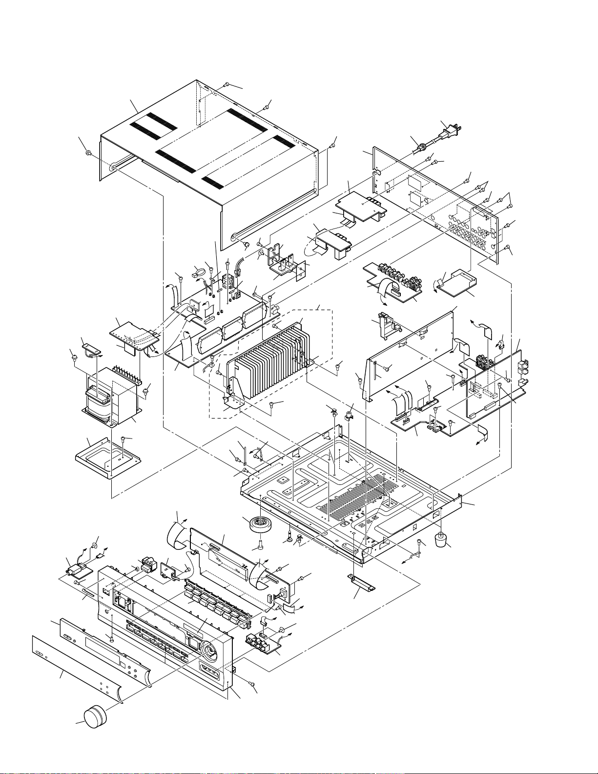
2.2 EXTERIOR
K
J
D
L
K
I
F
G
C
G
F
H
B
J
I
C
D
E
L
E
B
H
A
A
32
57
57
57
57
57
57
57
57
57
57
23
67
13
29
57
38
39
39
57
57
57
Accessories of
Front Panel 508
(No. 47)
57
70
Note
∗
1 :
Torque is 12 kg • cm
57
21
25
22
2
57
59
59
53
57
47
9
36
37
30
57
57
1
58
34
17
24
52
16
4
11
12
26
28
31
60
60
57
53
69
66
∗
1
∗
1
68
57
61
57
57
64
65
65
62
63
57
57
57
58
71
(KCXJI
Type
Only)
20
19
54
10
55
55
18
33
5
8
7
57
40
57
57
57
35
27
59
59
44
50
53
57
49
56
42
46
41
51
6
43
3
40
+ 2
– 0
5
VSX-D508
1 INPUT Assy AWX7207
2 FRONT Assy AWX7212
NSP 3 POWER SW Assy AWX7222
NSP 4 REAR SP Assy AWX7250
5 AMP Assy See Contrast table (2)
NSP 6 HEADPHONE Assy AWX7229
7 TRANS 1 Assy AWX7231
8 TRANS 2 Assy AWX7232
NSP 9 FRONT VIDEO Assy AWX7239
10 BARRIER Assy AWX7284
NSP 11 F.SP.CONNECT Assy AWX7285
NSP 12 R.C.SP.CONNECT Assy AWX7286
13 VIDEO Assy AWX7234
14 • • • • •
15 • • • • •
16 FRONT SP. Assy AWX7243
17 DOLBY DIGITAL Assy AWX7333
18 Power Transformer (T1) See Contrast table (2)
19 Fuse (FU1 : 10A) REK1087
20 Fuse (FU2 : 7A) VEK1027
21 FFC 21P (J2) ADD7100
22 FFC 15P (J4) ADD7102
23 FFC 13P (J5) ADD7103
24 FFC 17P (J8) ADD7107
25 FFC 26P (J3) ADD7118
26 AC Power Cord ADG7024
NSP 27 8P Shield Cable (J6) ADX7242
28 Cord Stopper CM-22C
29 Tuner Holder B AAD7490
NSP 30 Under Base D5 ANA7079
31 Rear Panel See Contrast table (2)
32 Bonnet Case AZN7762
33 Trans Frame ANG7193
34 DSP Shield ANG7196
NSP 35 Heat Sink Assy D5 ANH7095
36 Insulator PNW2766
37 Locking Card Spacer AEC7160
38 PCB Mold AMR2533
NSP 39 Card Spacer DEC1770
NSP 40 Binder RNE1277
41 Volume Knob 508 AAB7179
42 Sub Panel 508 AAD7482
43 Function Button AAD7483
44 Power Button AAD7440
45 • • • • •
46 Display Window R508 AAK7579
47 Front Panel 508 AMB7525
48 • • • • •
49 Name Plate PAM1776
50 LED Lens PNW2019
51 • • • • •
52 • • • • •
53 Screw ABA7009
54 Screw ABA7043
55 Screw ABA7044
56 • • • • •
57 Screw BBZ30P080FZK
58 Screw BBZ30P200FMC
59 Screw BPZ30P080FMC
60 Screw FBT40P080FZK
NSP 61 Binder (BK-1) ZCA-BK1
62 Heat Sink Angle F ANG7194
63 Heat Sink Angle R ANG7195
NSP 64 Heat Sink D5 ANH7090
65 Screw BBZ30P080FMC
NSP 66 FET Assy AWX7228
67 FM/AM TUNER Unit AXX7046
68 Sheet AEE7026
69 FET Angle ANG7186
70 Foot Assy REC1263
71 Fuse (FU701 : 10A) See Contrast table (2)
(1) EXTERIOR PARTS LIST
Mark No. Description Part No. Mark No. Description Part No.
Mark No. Symbol and Description
Part No.
Remarks
KUXJI Type KCXJI Type
5 AMP Assy AWX7223 AWX7331
18 Power Transformer (T1) ATS7234 ATS7235
31 Rear Panel 508U ANC7700 Not used
31 Rear Panel 508C Not used ANC7751
71 Fuse (FU701 : 10A) Not used REK1087
(2) CONTRAST TABLE
VSX-D508/KUXJI and KCXJI are constructed the same except for the following :
VSX-D508
6
A
B
C
D
1
23
4
1234
2/2
INPUT ASSY
(AWX7207)
A
VIDEO ASSY
(AWX7234)
N
FRONT VIDEO
ASSY
(AWX7239)
FM/AM TUNER
UNIT
(AXX7046)
O
DOLBY DIGITAL
ASSY
(AWX7333)
A
1/2,
A
3/3
P
P
1/3-
P
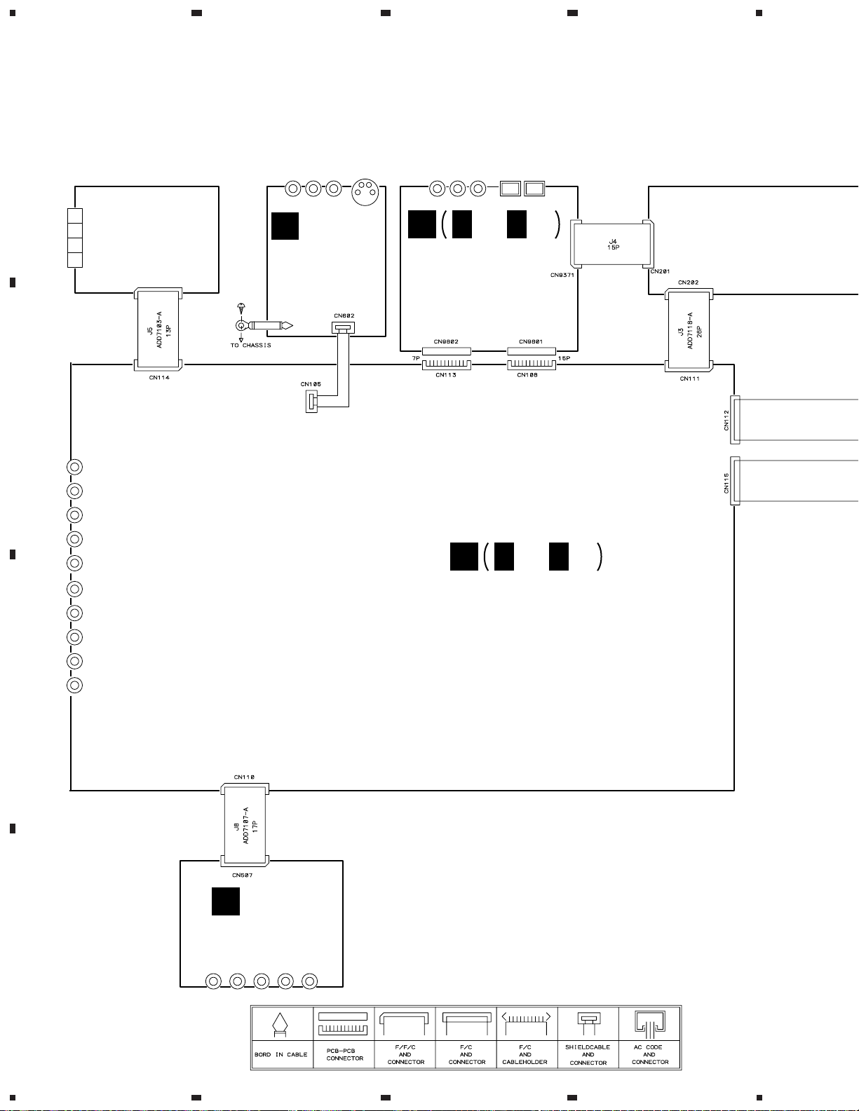
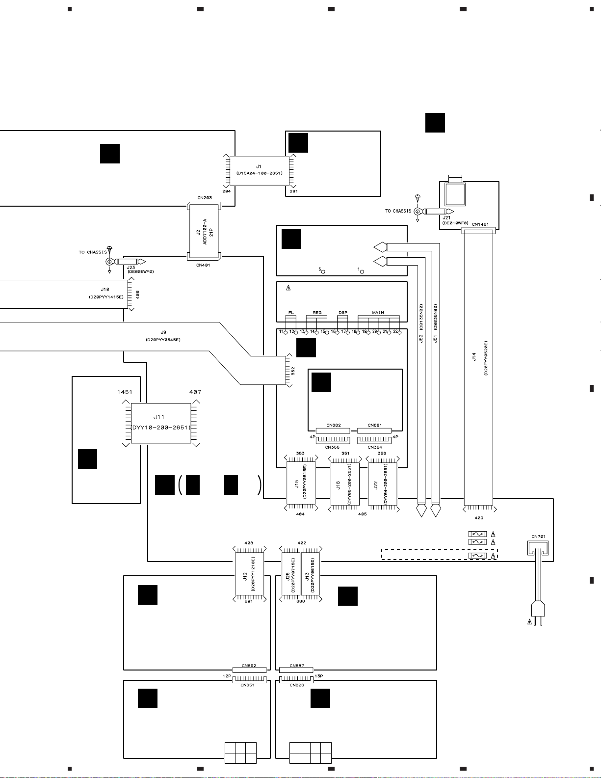
3. SCHEMATIC DIAGRAM
3.1 OVERALL WIRING CONNECTION DIAGRAM
VSX-D508
7
A
B
C
D
5
678
5
6
7
8
2/2
AMP ASSY
(KUXJI TYPE : AWX7223)
(KCXJI TYPE : AWX7331)
D
D
1/2,
D
R.C.SP.
CONNECT ASSY
(AWX7286)
F
FET ASSY
(AWX7228)
M
REAR SP ASSY
(AWX7250)
H
FRONT SP. ASSY
(AWX7243)
G
F.SP.
CONNECT ASSY
(AWX7285)
E
BARRIER ASSY
(AWX7284)
POWER TRANSFORMER (T1)
(KUXJI TYPE : ATS7234)
(KCXJI TYPE : ATS7235)
L
TRANS 2 ASSY
(AWX7232)
J
TRANS 1 ASSY
(AWX7231)
K
POWER SW
ASSY
(AWX7222)
HEADPHONE
ASSY
(AWX7229)
C
FRONT ASSY
(AWX7212)
B
I
AC POWER CORD
: ADG7024
J52 J51
FU1 REK1087 (10A)
FU701 REK1087 (10A)
KCXJI
TYPE
ONLY
FU2 VEK1027 (7A)
AC120V
60Hz
Note : When ordering service parts, be sure to refer to "EXPLODED VIEWS and PARTS LIST" or "PCB PARTS LIST".
VSX-D508
8
A
B
C
D
1
23
4
1234
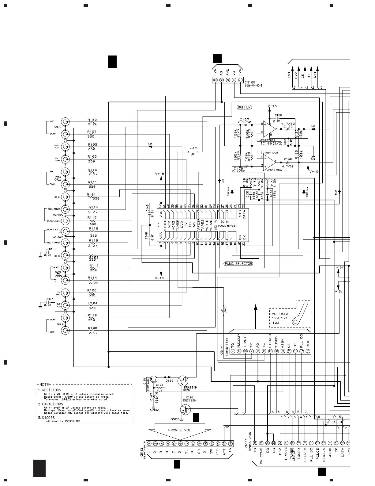
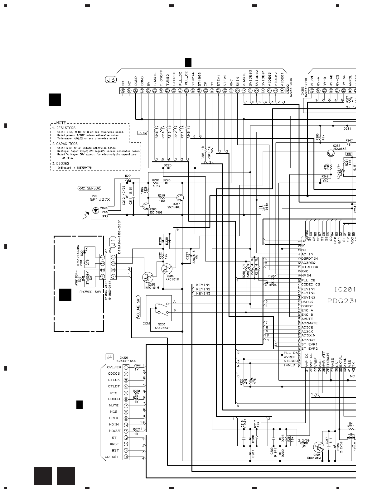
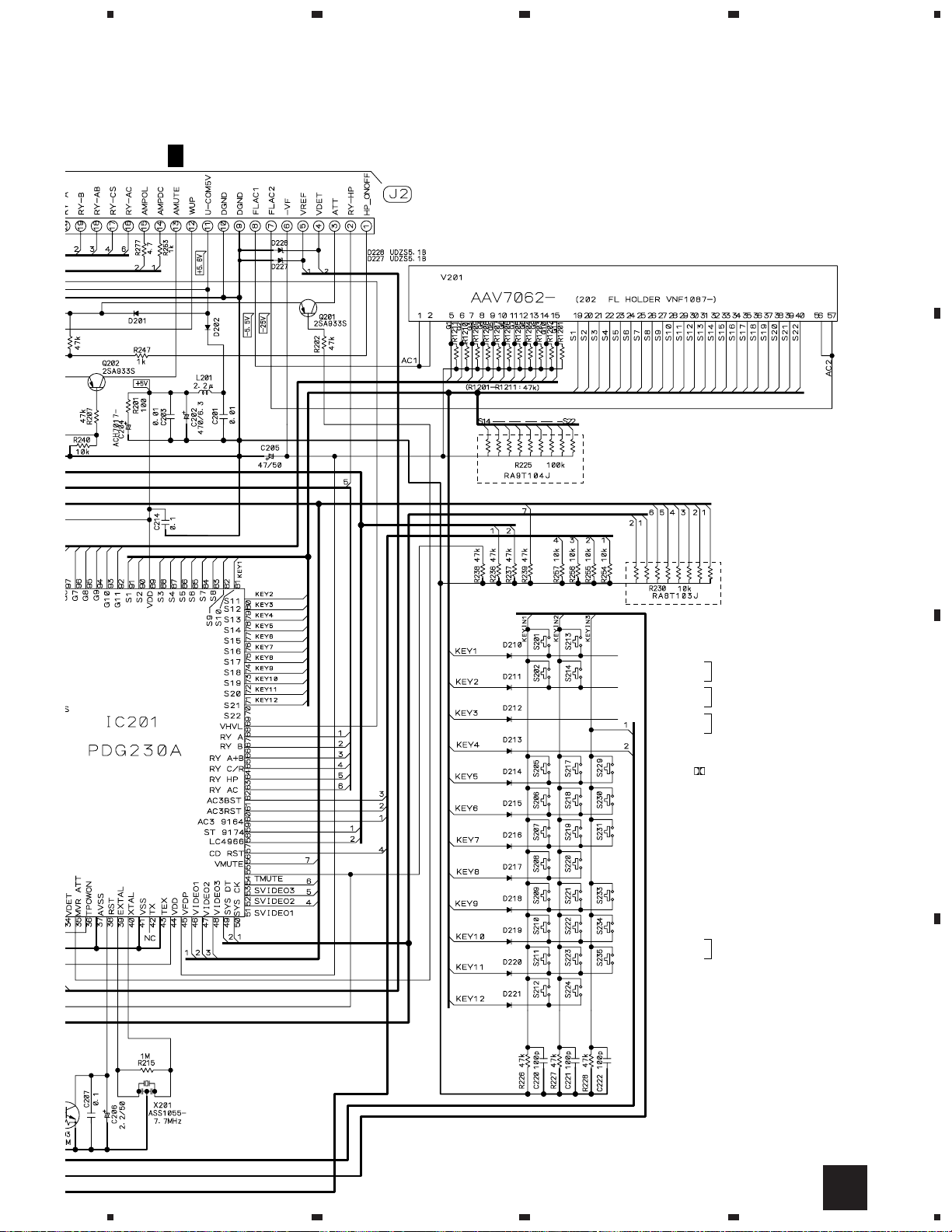
3.2 INPUT ASSY (1/2)
1/2
INPUT ASSY(1/2)
(AWX7207)
CN602
O
CN202
B
A
•
FUNCTION BLOCK
406
1/2
D
2/2
A
TO
FM/AM TUNER UNIT
JA103 (1/2)
AKB7113
JA102 (1/2)
AKB7113
JA101 (1/2)
AKB7113
JA101 (2/2)
AKB7113
JA102 (2/2)
AKB7113
JA103 (2/2)
AKB7113
1/2
A
VSX-D508
9
A
B
C
D
5
678
5
6
7
8
CN202
B
CN507
N
352
J
2/2
A
CN9801
1/3
P
CN9802
1/3
P
: AUDIO SIGNAL ROUTE
L ch
: AUDIO SIGNAL ROUTE (CENTER)
C ch
: AUDIO SIGNAL ROUTE (FRONT)
FL ch
1/2
A
VSX-D508
10
A
B
C
D
1
23
4
1234
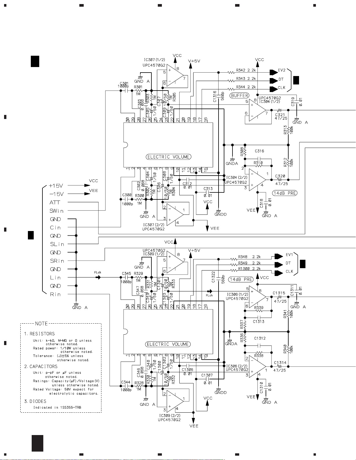
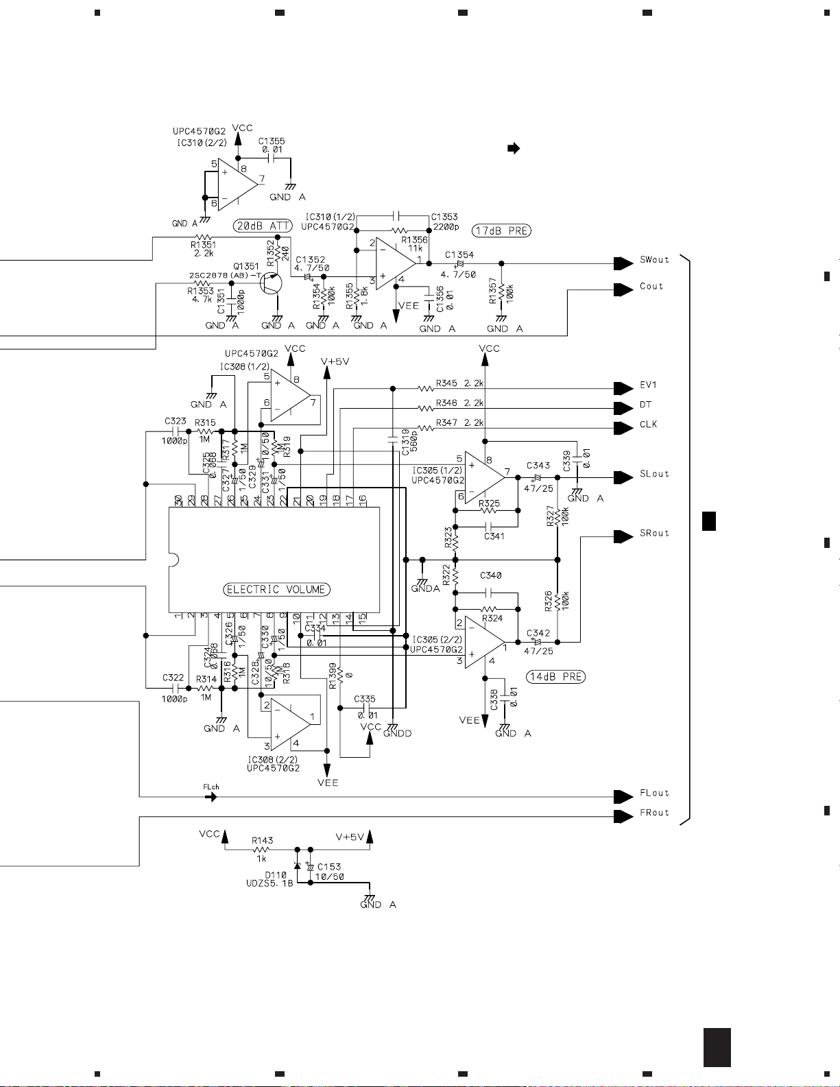
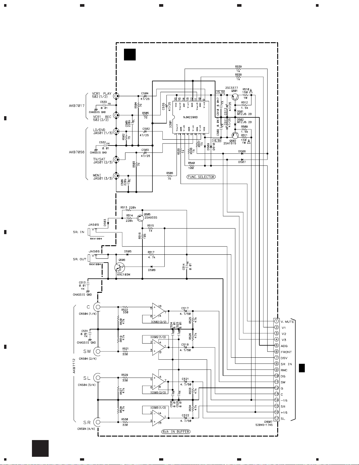
3.3 INPUT ASSY (2/2)
3k
120p
12k
12k
12k
68p
68p
3k
3k
1/2
A
2/2
INPUT ASSY(2/2)
(AWX7207)
A
•
E. VOL BLOCK
1/2
A
1/2
A
IC301
LC7535M
(LC7536M)
IC303
LC7535M
(LC7536M)
2/2
A
VSX-D508
11
A
B
C
D
5
678
5
6
7
8
12k
12k
120p
120p
3k
3k
1/2
A
: AUDIO SIGNAL ROUTE (FRONT)
FL ch
IC302
LC7535M
(LC7536M)
2/2
A
VSX-D508
12
A
B
C
D
1
23
4
1234
3.4 FRONT and POWER SW ASSEMBLIES
FRONT ASSY
(AWX7212)
B
POWER SW
ASSY
(AWX7222)
C
CN111
1/2
A
CN9371
2/3
P
MASTER VOLUME
B C
VSX-D508
13
A
B
C
D
5
678
5
6
7
8
CN401
2/2
D
FRONT ASSY
S201 : MIDNIGHT
S202 : DSP MODE
S205 : –
S206 : +
S207 : –
S208 : +
S209 : A
S210 : B
S211 : LOUDNESS
S212 : DIRECT
S213 : (DOLBY)
S214 : SIGNAL SELECT
S217 : TV/SAT
S218 : VIDEO
S219 : CD
S220 : TUNER
S221 : VCR
S222 : DVD/LD
S223 : MD/TAPE
S224 : AUX
S229 : CLASS
S230 : MEMORY
S231 : MPX MODE
S233 : –
S234 : +
S235 : CHANNEL SELECT
S250 : MASTER VOLUME
BASS
TREBLE
CHANNEL LEVEL
SPEAKERS
B
VSX-D508
14
A
B
C
D
1
23
4
1234
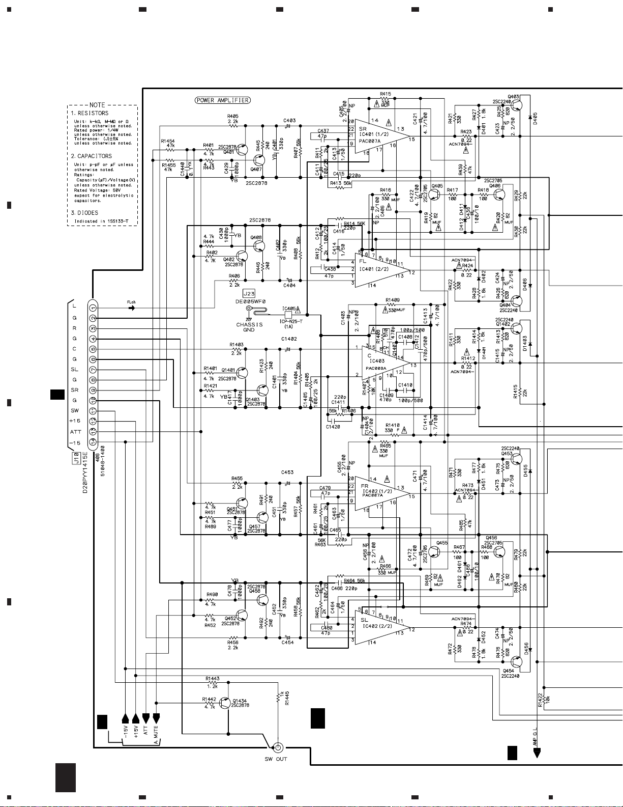
3.5 AMP (1/2), F.SP.CONNECT, R.C.SP.CONNECT, FRONT SP. and REAR SP
ASSEMBLIES
4.7/50
4.7/50
4.7/50
18p
4.7/50
4.7/50
JA413
AKB7111
1/2
AMP ASSY(1/2)
(KUXJI TYPE : AWX7223)
(KCXJI TYPE : AWX7331)
D
CN112
1/2
A
2/2
D
2/2
D
1/2
D

VSX-D508
15
A
B
C
D
5
678
5
6
7
8
0.1
0.1
AKE7006
22k
1.2k
JA653
AKB7111
0.1
AKE7041
0.1
0.1
REAR SP ASSY
(AWX7250)
H
R.C.SP. CONNECT ASSY
(AWX7286)
F
F.SP. CONNECT ASSY
(AWX7285)
E
FRONT SP. ASSY
(AWX7243)
G
2/2
D
2/2
D
: AUDIO SIGNAL ROUTE (FRONT)
FL ch
CAUTION : FOR CONTINUED PROTECTION AGAINST RISK OF FIRE,
REPLACE ONLY WITH SAME TYPE NO. ICP-N25, MFD BY
ROHM CO., LTD. FOR IC404 and IC405.
HGFE
1/2
D

VSX-D508
16
A
B
C
D
1
23
4
1234
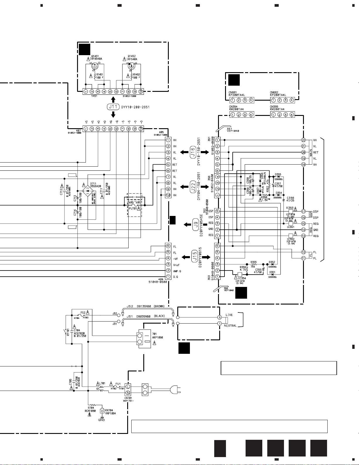
3.6 AMP (2/2), HEADPHONE, TRANS 2, TRANS 1, BARRIER and FET
ASSEMBLIES
2/2
AMP ASSY(2/2)
(KUXJI TYPE : AWX7223)
(KCXJI TYPE : AWX7331)
D
HEADPHONE
ASSY
(AWX7229)
I
1/2
D
CN203
B
ATT1223
1000/25
: AUDIO SIGNAL ROUTE
(HEAD PHONE)
HP
+43.1
–43.1
2/2
D
I
VSX-D508
17
A
B
C
D
5
678
5
6
7
8
AC120V
60Hz
TRANS 1 ASSY
(AWX7231)
K
TRANS 2 ASSY
(AWX7232)
J
BARRIER ASSY
(AWX7284)
L
FET ASSY (AWX7228)
M
CN115
KCXJI
TYPE
KUXJI
TYPE
MAIN TRANS.
1/2
A
MAIN TRANS.
AC OUTLET
AC POWER CORD
ADG7024
LIVE
NEUTRAL
REK1087
NP
10A
REK1087
10A
ATF7018
VEK1027
7A
+66.1
–66.1
• NOTE FOR FUSE REPLACEMENT
FOR CONTINUED PROTECTION AGAINST RISK OF FIRE.
REPLACE WITH SAME TYPE AND RATINGS ONLY.
CAUTION -
CAUTION : FOR CONTINUED PROTECTION AGAINST RISK OF FIRE,
REPLACE ONLY WITH SAME TYPE NO. ICP-N70, MFD BY
ROHM CO., LTD. FOR IC351 - IC354.
2/2
D
MLKJ
VSX-D508
18
A
B
C
D
1
23
4
1234
3.7 VIDEO ASSY
N
VIDEO ASSY
(AWX7234)
N
CN110
1/2
A
NJM4558D-D
NJM4558D-D
NJM4558D-D
NJM4558D-D
VSX-D508
19
A
B
C
D
1
234
1
2
3
4
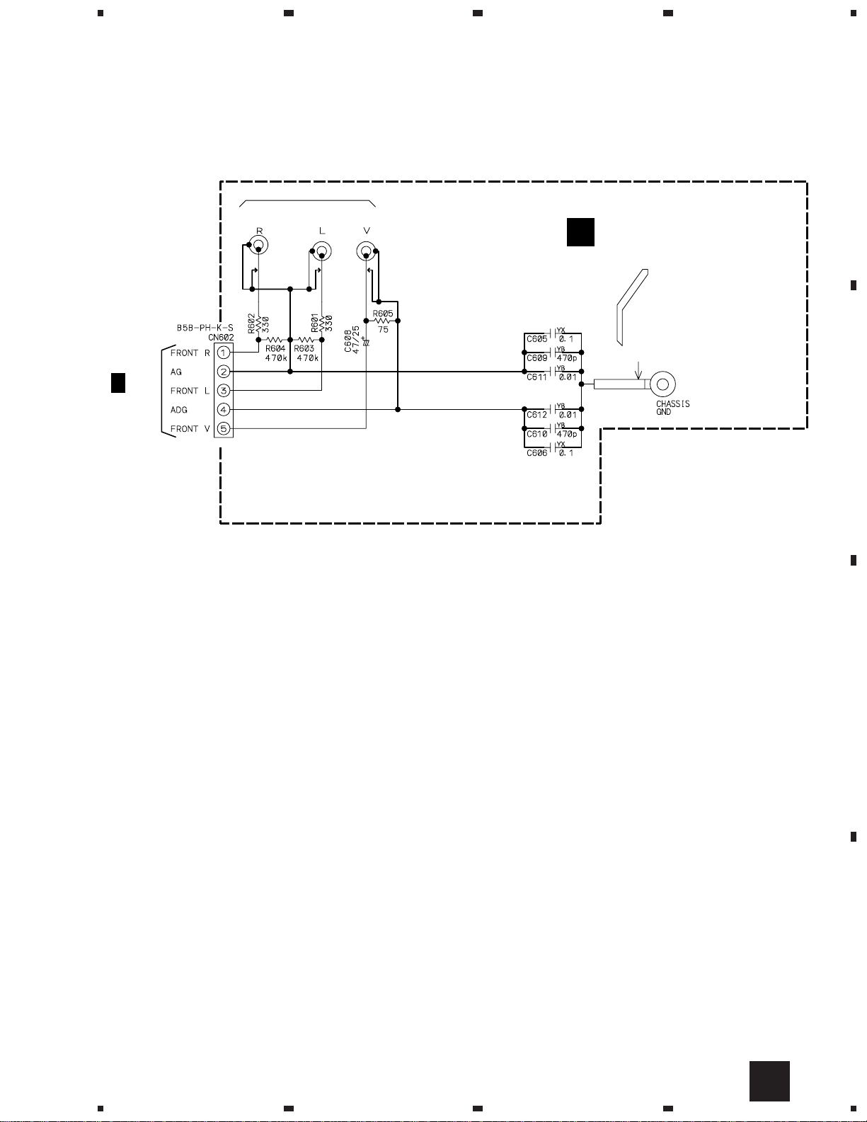
O
Y20 ADX7248
PCB BINDER
601
VEF1040
FRONT VIDEO ASSY
(AWX7239)
O
CN105
1/2
A
CN601 AKB7085
3.8 FRONT VIDEO ASSY
VSX-D508
20
A
B
C
D
1
23
4
1234
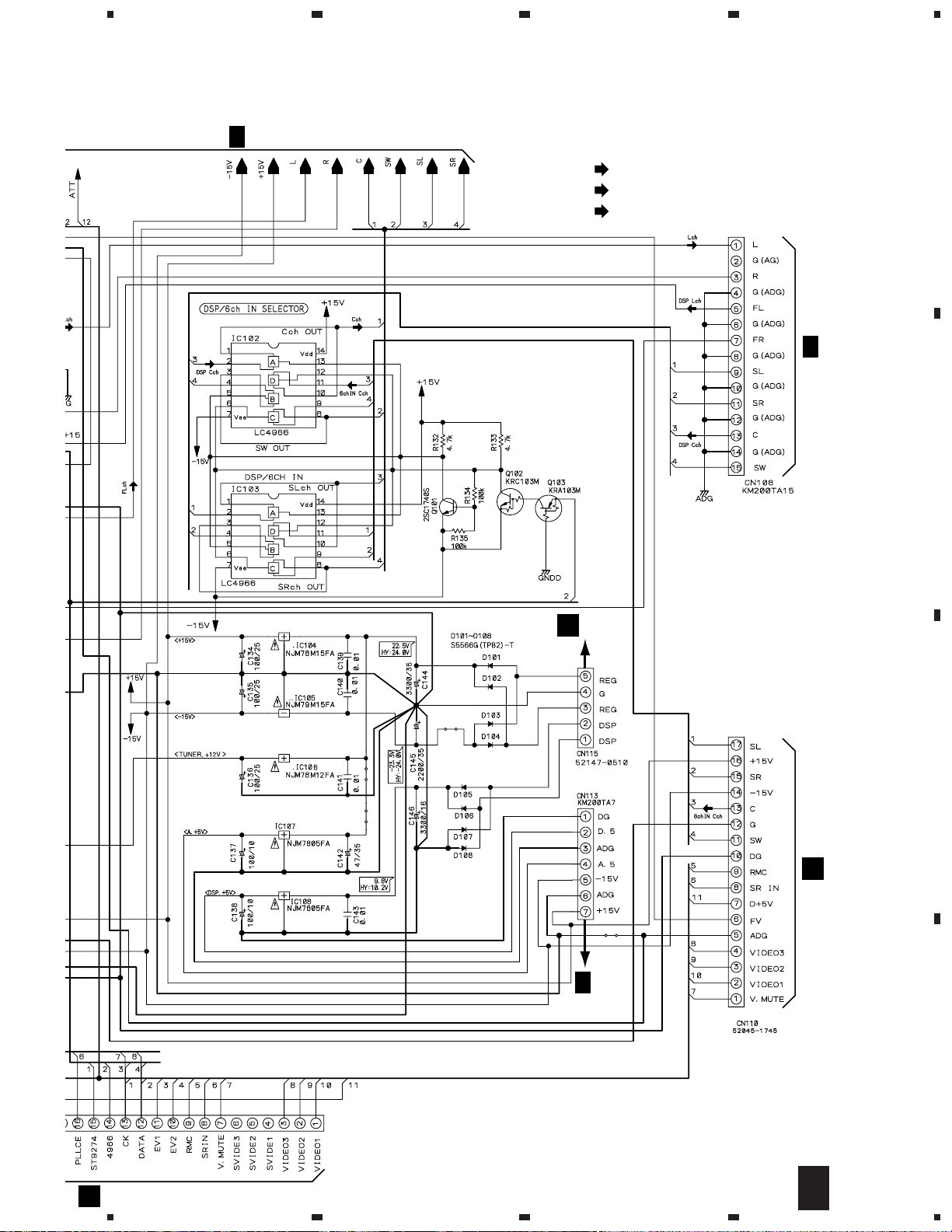
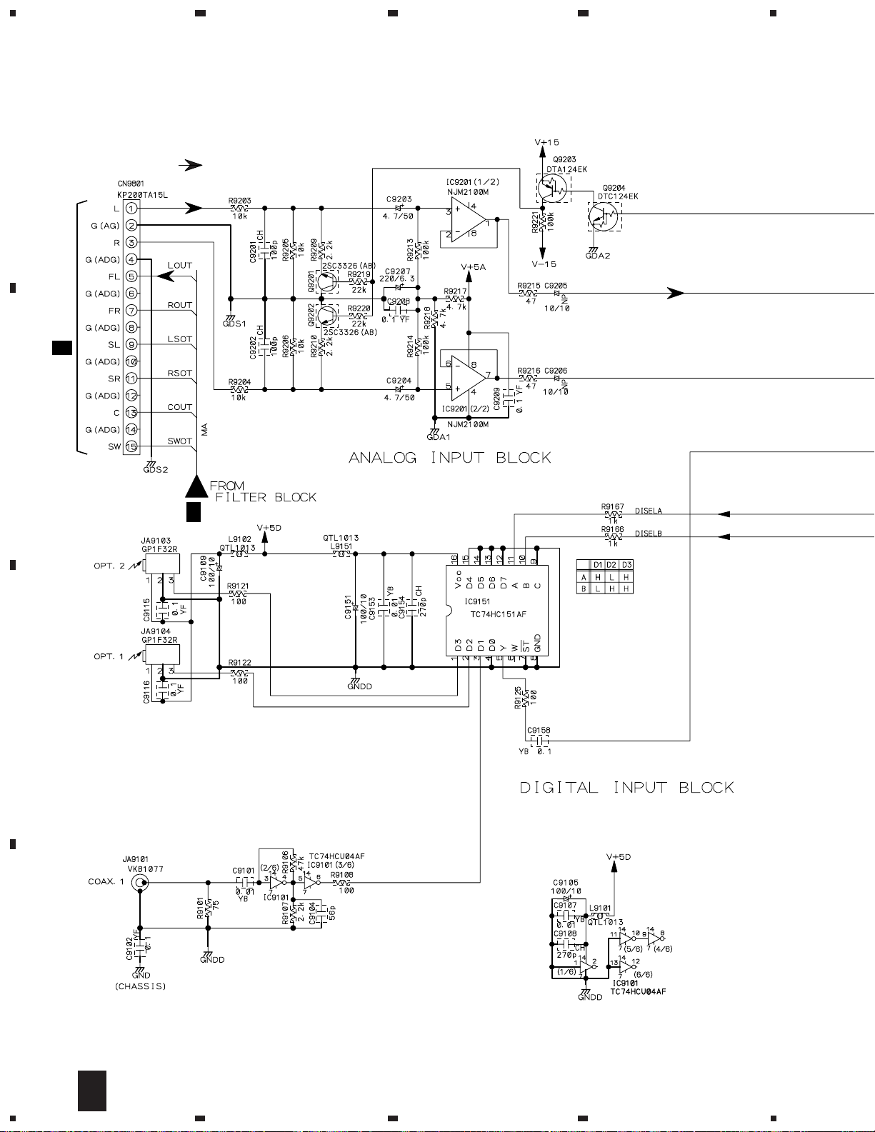
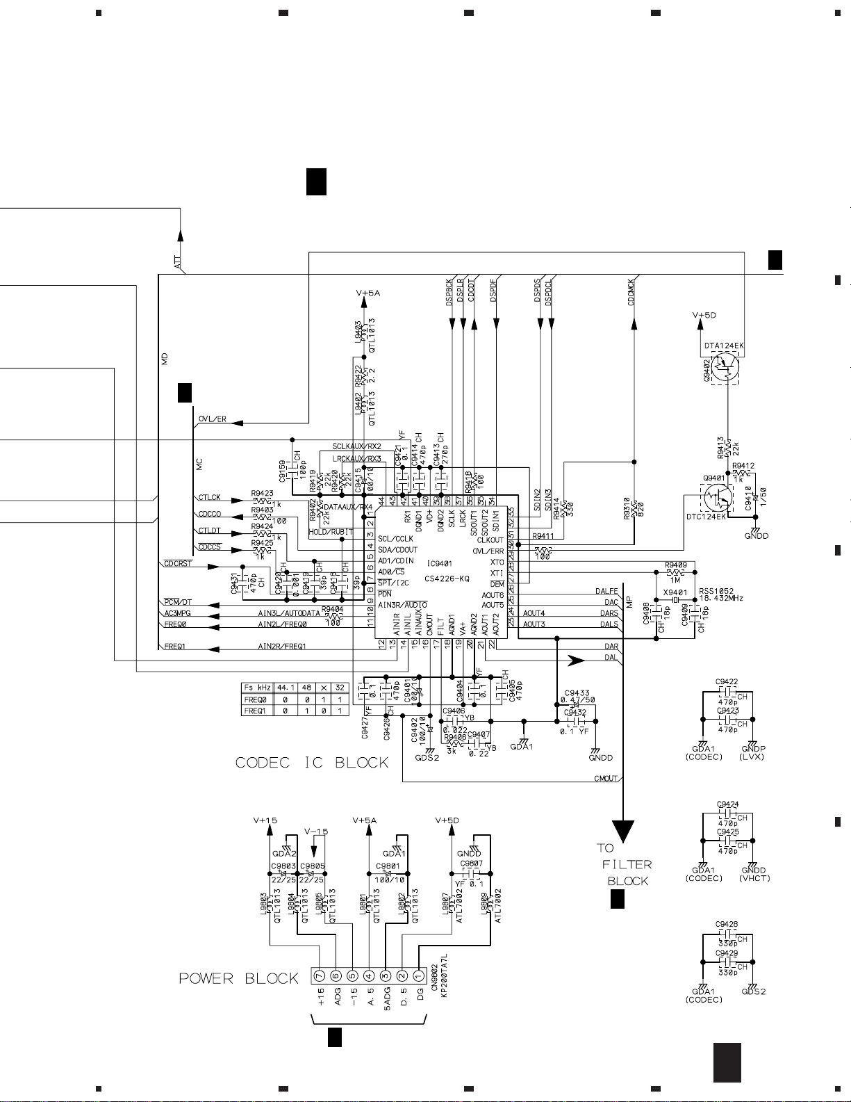
3.9 DOLBY DIGITAL ASSY (1/3)
3/3
P
CN108
1/2
A
: AUDIO SIGNAL ROUTE
1/3
P
VSX-D508
21
A
B
C
D
5
678
5
6
7
8
1/3
DOLBY DIGITAL ASSY(1/3)
(AWX7333)
P
CN113
1/2
A
2/3
P
2/3
P
2/3
P
•
INPUT & CODEC BLOCK
1/3
P
 Loading...