


VSX-917V
AUDIO/VIDEO MULTI-CHANNEL
RECEIVER
VSX-917V
Register your product at
www.pioneerelectronics.com (US)
www.pioneerelectronics.ca (Canada)
• Protect your new investment
The details of your purchase will be on file for reference in the event of an
insurance claim such as loss or theft.
• Receive free tips, updates and service bulletins on
your new product
• Improve product development
Your input helps us continue to design products that meet your needs.
• Receive a free Pioneer newsletter
Registered customers can opt in to receive a monthly newsletter.
Operating Instructions
WARNING – TO PREVENT FIRE OR SHOCK
HAZARD, DO NOT EXPOSE THIS
APPLIANCE TO RAIN OR MOISTURE.
CAUTION – PREVENT ELECTRIC SHOCK DO
NOT USE THIS (POLARIZED) PLUG
WITH AN EXTENSION CORD.
RECEPTACLE OR OTHER OUTLET
UNLESS THE BLADES CAN BE
FULLY INSERTED TO PREVENT
BLADE EXPOSURE.
ATTENTION –
POUR PREVENIR LES CHOCS
ELECTRIQUES NE PAS UTILISER
D1-4-2-1_En
If the AC plug of this unit does not match the AC
outlet you want to use, the plug must be removed
and appropriate one fitted. Replacement and
mounting of an AC plug on the power supply cord of
this unit should be performed only by qualified
service personnel. If connected to an AC outlet, the
cut-off plug can cause severe electrical shock. Make
sure it is properly disposed of after removal.
The equipment should be disconnected by removing
the mains plug from the wall socket when left
unused for a long period of time (for example, when
on vacation).
For U.S. and Australia Model
D3-4-2-2-1a_A_En
CETTE FICHE POLARISEE AVEC UN
PROLONGATEUR UNE PRISE DE
COURANT OU UNE AUTRE SORTIE
DE COURANT, SAUF SI LES LAMES
PEUVENT ETRE INSEREES A FOND
SANS EN LAISSER AUCUNE PARTIE
A DECOUVVERT.
D2-4-4-1_EF
C67-7-3_En
IMPORTANT NOTICE – THE SERIAL NUMBER FOR THIS EQUIPMENT IS LOCATED IN THE REAR.
PLEASE WRITE THIS SERIAL NUMBER ON YOUR ENCLOSED WARRANTY CARD AND
KEEP IN A SECURE AREA. THIS IS FOR YOUR SECURITY.
D1-4-2-6-1_En
NOTE: This equipment has been tested and found to comply with the limits for a Class B digital device, pursuant to
Part 15 of the FCC Rules. These limits are designed to provide reasonable protection against harmful interference in
a residential installation. This equipment generates, uses, and can radiate radio frequency energy and, if not
installed and used in accordance with the instructions, may cause harmful interference to radio communications.
However, there is no guarantee that interference will not occur in a particular installation. If this equipment does
cause harmful interference to radio or television reception, which can be determined by turning the equipment off
and on, the user is encouraged to try to correct the interference by one or more of the following measures:
– Reorient or relocate the receiving antenna.
– Increase the separation between the equipment and receiver.
– Connect the equipment into an outlet on a circuit different from that to which the receiver is connected.
– Consult the dealer or an experienced radio/TV technician for help.
D8-10-1-2_En
This Class B digital apparatus complies with Canadian ICES-003.
Cet appareil numérique de la Classe B est conforme à la norme NMB-003 du Canada.
D8-10-1-3_EF
Information to User
Alteration or modifications carried out without appropriate authorization may invalidate the user’s right to operate
the equipment.
D8-10-2_En
CAUTION: This product satisfies FCC regulations when shielded cables and connectors are used to connect the
unit to other equipment. To prevent electromagnetic interference with electric appliances such as radios and
televisions, use shielded cables and connectors for connections.
FEDERAL COMMUNICATIONS COMMISSION DECLARATION OF CONFORMITY
This device complies with part 15 of the FCC Rules. Operation is subject to the following two conditions: (1) This
device may not cause harmful interference, and (2) this device must accept any interference received, including
interference that may cause undesired operation.
Product Name: AUDIO/VIDEO MULTI-CHANNEL RECEIVER
Model Number: VSX-917V-K, VSX-917V-S
Responsible Party Name: PIONEER ELECTRONICS SERVICE INC.
Address: 1925 E. DOMINGUEZ ST. LONG BEACH, CA 90801-1760, USA
Phone: 1-800-421-1404
D8-10-3a_En
The lightning flash with arrowhead, within
an equilateral triangle, is intended to alert
the user to the presence of uninsulated
"dangerous voltage" within the product's
enclosure that may be of sufficient
magnitude to constitute a risk of electric
shock to persons.
CAUTION
RISK OF ELECTRIC SHOCK
DO NOT OPEN
CAUTION:
TO PREVENT THE RISK OF ELECTRIC
SHOCK, DO NOT REMOVE COVER (OR
BACK). NO USER-SERVICEABLE PARTS
INSIDE. REFER SERVICING TO QUALIFIED
SERVICE PERSONNEL.
The exclamation point within an equilateral
triangle is intended to alert the user to the
presence of important operating and
maintenance (servicing) instructions in the
literature accompanying the appliance.
D1-4-2-3_En
READ INSTRUCTIONS — All the safety and
operating instructions should be read before the
product is operated.
RETAIN INSTRUCTIONS — The safety and
operating instructions should be retained for
future reference.
HEED WARNINGS — All warnings on the product
and in the operating instructions should be
adhered to.
FOLLOW INSTRUCTIONS — All operating and use
instructions should be followed.
CLEANING — The product should be cleaned only
with a polishing cloth or a soft dry cloth. Never
clean with furniture wax, benzine, insecticides
or other volatile liquids since they may corrode
the cabinet.
ATTACHMENTS — Do not use attachments not
recommended by the product manufacturer as
they may cause hazards.
WATER AND MOISTURE — Do not use this
product near water — for example, near a
bathtub, wash bowl, kitchen sink, or laundry
tub; in a wet basement; or near a swimming
pool; and the like.
ACCESSORIES — Do not place this product on an
unstable cart, stand, tripod, bracket, or table.
The product may fall, causing serious injury to a
child or adult, and serious damage to the
product. Use only with a cart, stand, tripod,
bracket, or table recommended by the
manufacturer, or sold with the product. Any
mounting of the product should follow the
manufacturer’s instructions, and should use a
mounting accessory recommended by the
manufacturer.
CART — A product and cart combination should be
moved with care. Quick stops, excessive force,
and uneven surfaces may cause the product
and cart combination to overturn.
VENTILATION — Slots and openings in the cabinet
are provided for ventilation and to ensure
reliable operation of the product and to protect
it from overheating, and these openings must
not be blocked or covered. The openings should
never be blocked by placing the product on a
bed, sofa, rug, or other similar surface. This
product should not be placed in a built-in
installation such as a bookcase or rack unless
proper ventilation is provided or the
manufacturer’s instructions have been adhered
to.
POWER SOURCES — This product should be
operated only from the type of power source
indicated on the marking label. If you are not
sure of the type of power supply to your home,
consult your product dealer or local power
company.
LOCATION – The appliance should be installed in a
stable location.
NONUSE PERIODS – The power cord of the
appliance should be unplugged from the outlet
when left un-used for a long period of time.
GROUNDING OR POLARIZATION
• If this product is equipped with a polarized
alternating current line plug (a plug having one
blade wider than the other), it will fit into the
outlet only one way. This is a safety feature. If
you are unable to insert the plug fully into the
outlet, try reversing the plug. If the plug should
still fail to fit, contact your electrician to replace
your obsolete outlet. Do not defeat the safety
purpose of the polarized plug.
• If this product is equipped with a three-wire
grounding type plug, a plug having a third
(grounding) pin, it will only fit into a grounding
type power outlet. This is a safety feature. If you
are unable to insert the plug into the outlet,
contact your electrician to replace your obsolete
outlet. Do not defeat the safety purpose of the
grounding type plug.
POWER-CORD PROTECTION — Power-supply
cords should be routed so that they are not likely
to be walked on or pinched by items placed
upon or against them, paying particular
attention to cords at plugs, convenience
receptacles, and the point where they exit from
the product.
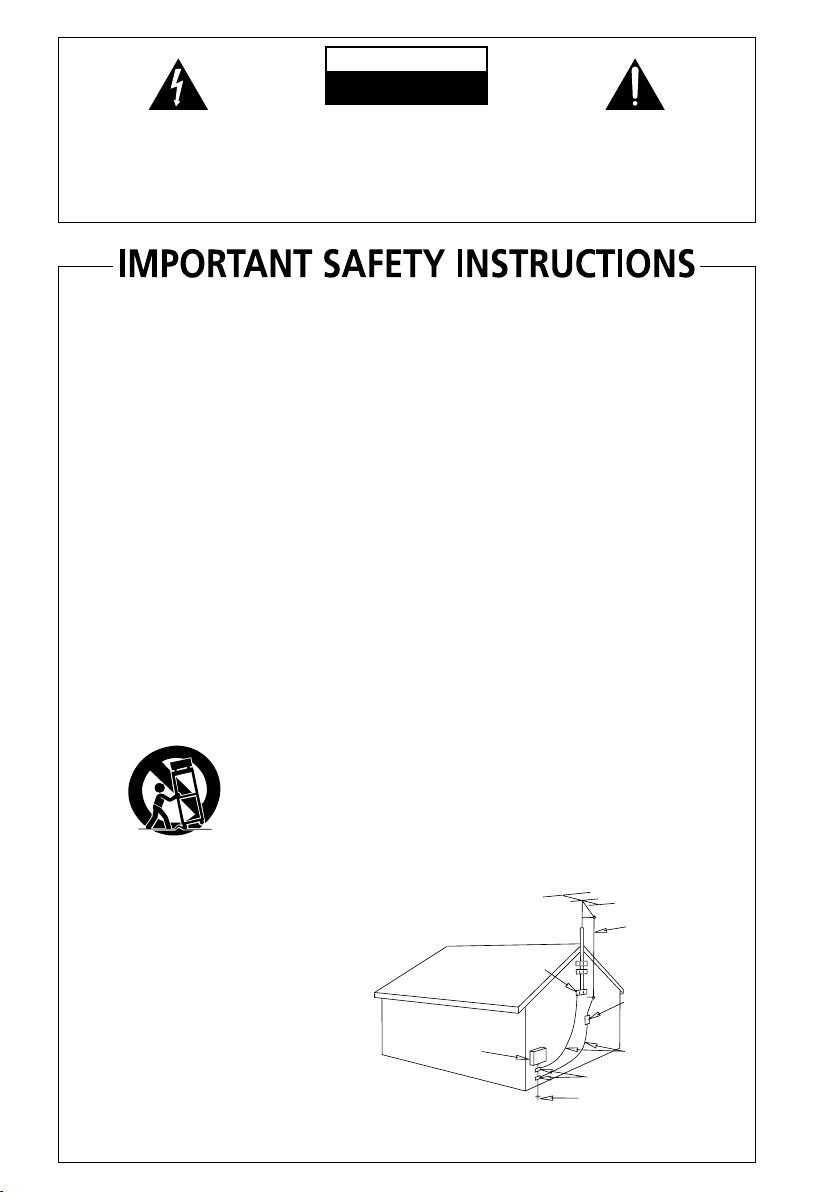
OUTDOOR ANTENNA GROUNDING — If an
outside antenna or cable system is connected to
the product, be sure the antenna or cable
system is grounded so as to provide some
protection against voltage surges and built-up
static charges. Article 810 of the National
Electrical Code, ANSI/NFPA 70, provides
information with regard to proper grounding of
the mast and supporting structure, grounding of
the lead-in wire to an antenna discharge unit,
size of grounding conductors, location of
antenna-discharge unit, connection to
grounding electrodes, and requirements for the
grounding electrode. See Figure A.
LIGHTNING — For added protection for this
product during a lightning storm, or when it is
left unattended and unused for long periods of
time, unplug it from the wall outlet and
disconnect the antenna or cable system. This
will prevent damage to the product due to
lightning and power-line surges.
POWER LINES — An outside antenna system
should not be located in the vicinity of overhead
power lines or other electric light or power
circuits, or where it can fall into such power
lines or circuits. When installing an outside
antenna system, extreme care should be taken
to keep from touching such power lines or
circuits as contact with them might be fatal.
OVERLOADING — Do not overload wall outlets,
extension cords, or integral convenience
receptacles as this can result in a risk of fire or
electric shock.
ELECTRIC
SERVICE
EQUIPMENT
Fig. A
OBJECT AND LIQUID ENTRY — Never push
objects of any kind into this product through
openings as they may touch dangerous voltage
points or short-out parts that could result in a
fire or electric shock. Never spill liquid of any
kind on the product.
SERVICING — Do not attempt to service this
product yourself as opening or removing covers
may expose you to dangerous voltage or other
hazards. Refer all servicing to qualified service
personnel.
DAMAGE REQUIRING SERVICE — Unplug this
product from the wall outlet and refer servicing
to qualified service personnel under the
following conditions:
• When the power-supply cord or plug is
damaged.
• If liquid has been spilled, or objects have fallen
into the product.
• If the product has been exposed to rain or water.
• If the product does not operate normally by
following the operating instructions. Adjust only
those controls that are covered by the operating
instructions as an improper adjustment of other
controls may result in damage and will often
require extensive work by a qualified technician
to restore the product to its normal operation.
• If the product has been dropped or damaged in
any way.
• When the product exhibits a distinct change in
performance — this indicates a need for service.
REPLACEMENT PARTS — When replacement parts
are required, be sure the service technician has
used replacement parts specified by the
manufacturer or have the same characteristics
as the original part. Unauthorized substitutions
may result in fire, electric shock, or other
hazards.
SAFETY CHECK — Upon completion of any service
or repairs to this product, ask the service
technician to perform safety checks to
determine that the product is in proper
operating condition.
WALL OR CEILING MOUNTING — The product
should not be mounted to a wall or ceiling.
HEAT — The product should be situated away from
heat sources such as radiators, heat registers,
stoves, or other products (including amplifiers)
that produce heat.
ANTENNA
LEAD IN
GROUND
CLAMP
WIRE
ANTENNA
DISCHARGE UNIT
(NEC SECTION 810-20)
GROUNDING CONDUCTORS
(NEC SECTION 810-21)
GROUND CLAMPS
POWER SERVICE GROUNDING
ELECTRODE SYSTEM
(NEC ART 250, PART H)
NEC — NATIONAL ELECTRICAL CODE
D1-4-2-2_En

Thank you for buying this Pioneer product. Please read through these operating instructions so you will know how to operate
your model properly. After you have finished reading the instructions, put them away in a safe place for future reference.
Contents
01 Before you start
Checking what’s in the box . . . . . . . . . . . . . . . 6
Loading the batteries . . . . . . . . . . . . . . . . . . . 6
Installing the receiver . . . . . . . . . . . . . . . . . . . 6
Ventilation. . . . . . . . . . . . . . . . . . . . . . . . . . . . 6
02 5 minute guide
Introduction to home theater . . . . . . . . . . . . . 7
Listening to Surround Sound . . . . . . . . . . . . . 7
Automatically setting up for surround sound
(MCACC). . . . . . . . . . . . . . . . . . . . . . . . . . . . . 8
Other problems when using the Auto
MCACC Setup . . . . . . . . . . . . . . . . . . . . . . 10
Better sound using Phase Control . . . . . . . . 10
03 Connecting up
Making cable connections . . . . . . . . . . . . . . 11
Analog audio cables. . . . . . . . . . . . . . . . . . 11
Digital audio cables . . . . . . . . . . . . . . . . . . 11
Video cables . . . . . . . . . . . . . . . . . . . . . . . . 11
About the video converter . . . . . . . . . . . . . . . 12
Connecting a DVD player and TV . . . . . . . . . 13
Connecting the multichannel analog
outputs. . . . . . . . . . . . . . . . . . . . . . . . . . . . 14
Connecting a satellite receiver or other
digital set-top box . . . . . . . . . . . . . . . . . . . . . 14
Connecting other audio components . . . . . . 15
About the WMA9 Pro decoder . . . . . . . . . . 15
Connecting other video components . . . . . . 16
Using the component video jacks. . . . . . . . 17
Connecting to the front panel video
terminal . . . . . . . . . . . . . . . . . . . . . . . . . . . 17
Connecting to the front panel audio
mini jack. . . . . . . . . . . . . . . . . . . . . . . . . . . 17
Connecting antennas . . . . . . . . . . . . . . . . . . 18
Using external antennas. . . . . . . . . . . . . . . 18
Connecting the speakers . . . . . . . . . . . . . . . 19
Hints on speaker placement. . . . . . . . . . . . 20
AC outlet. . . . . . . . . . . . . . . . . . . . . . . . . . . . 21
04 Controls and displays
Front panel . . . . . . . . . . . . . . . . . . . . . . . . . . 22
Display . . . . . . . . . . . . . . . . . . . . . . . . . . . . . 23
Remote control. . . . . . . . . . . . . . . . . . . . . . . 25
Operating range of remote control . . . . . . . 27
05 Listening to your system
Auto playback . . . . . . . . . . . . . . . . . . . . . . . . 28
Listening in surround sound . . . . . . . . . . . . . 28
Using the Advanced surround effects. . . . . 29
Setting the effect options . . . . . . . . . . . . . . 29
Listening in stereo. . . . . . . . . . . . . . . . . . . . . 30
Using Front Stage Surround Advance . . . . . . 30
Using Stream Direct . . . . . . . . . . . . . . . . . . . 30
Listening with Acoustic Calibration EQ . . . . . 31
Using surround back channel processing. . . 31
Using Virtual Surround Back (VSB). . . . . . . 32
Using Midnight and Loudness. . . . . . . . . . . . 32
Using the Sound Retriever. . . . . . . . . . . . . . . 33
Enhancing dialog . . . . . . . . . . . . . . . . . . . . . 33
Using the tone controls. . . . . . . . . . . . . . . . . 33
Playing other sources . . . . . . . . . . . . . . . . . . 33
Choosing the input signal . . . . . . . . . . . . . . . 33
Selecting the multichannel analog inputs . . . 34
Selecting the front audio inputs . . . . . . . . . . 34
06 The System Setup menu
Making receiver settings from the System
Setup menu. . . . . . . . . . . . . . . . . . . . . . . . . . 35
Surround back speaker setting . . . . . . . . . . . 35
Manual MCACC speaker setup . . . . . . . . . . . 36
Fine Channel Level . . . . . . . . . . . . . . . . . . . 37
Fine Speaker Distance . . . . . . . . . . . . . . . . 37
Acoustic Calibration EQ . . . . . . . . . . . . . . . 38
Manual speaker setup. . . . . . . . . . . . . . . . . . 40
Speaker Setting . . . . . . . . . . . . . . . . . . . . . 41
Crossover Network . . . . . . . . . . . . . . . . . . . 42
Channel Level . . . . . . . . . . . . . . . . . . . . . . . 42
Speaker Distance . . . . . . . . . . . . . . . . . . . . 43
07 Using the tuner
Listening to the radio. . . . . . . . . . . . . . . . . . . 44
Improving FM stereo sound . . . . . . . . . . . . 44
Tuning directly to a station . . . . . . . . . . . . . 44
Saving station presets . . . . . . . . . . . . . . . . . . 44
Naming station presets. . . . . . . . . . . . . . . . 45
Listening to station presets. . . . . . . . . . . . . 45
08 Making recordings
Making an audio or a video recording . . . . . . 46
09 Controlling the rest of your
system
Operating other Pioneer components . . . . . . 47
Setting the remote to control other
components . . . . . . . . . . . . . . . . . . . . . . . . . 47
Selecting preset codes directly . . . . . . . . . . . 48
Erasing one of the remote control button
settings . . . . . . . . . . . . . . . . . . . . . . . . . . . . . 48
Erasing all of the remote control presets. . . . 48
Direct function . . . . . . . . . . . . . . . . . . . . . . . 49
Confirming preset codes . . . . . . . . . . . . . . . . 49
Controls for TVs. . . . . . . . . . . . . . . . . . . . . . . 50
Controls for other components . . . . . . . . . . . 51
10 Other connections
Using XM Radio . . . . . . . . . . . . . . . . . . . . . . 53
Connecting your XM Radio receiver . . . . . . 53
Listening to XM Radio. . . . . . . . . . . . . . . . . 54
Using XM HD Surround . . . . . . . . . . . . . . . 54
Saving channel presets. . . . . . . . . . . . . . . . 54
Using the XM Menu . . . . . . . . . . . . . . . . . . 55
Using SIRIUS Radio . . . . . . . . . . . . . . . . . . . 55
Connecting your SIRIUS Connect Tuner . . . 55
Listening to SIRIUS Radio. . . . . . . . . . . . . . 56
Saving channel presets. . . . . . . . . . . . . . . . 57
Using the SIRIUS Menu . . . . . . . . . . . . . . . 57
Connecting using HDMI . . . . . . . . . . . . . . . . 57
About HDMI . . . . . . . . . . . . . . . . . . . . . . . . . 58
Second Zone speaker B setup. . . . . . . . . . . . 59
Switching the speaker system . . . . . . . . . . 59
Bi-amping your front speakers. . . . . . . . . . . . 59
Bi-wiring your speakers . . . . . . . . . . . . . . . . . 60
Using this receiver with a Pioneer plasma
display. . . . . . . . . . . . . . . . . . . . . . . . . . . . . . 60
Using the SR+ mode with a Pioneer
plasma display . . . . . . . . . . . . . . . . . . . . . . 61
11 Other Settings
The Input Assign menu . . . . . . . . . . . . . . . . . 62
The Other Setup menu. . . . . . . . . . . . . . . . . . 63
Dynamic Range Control Setup . . . . . . . . . . 64
Dual Mono Setup . . . . . . . . . . . . . . . . . . . . 64
LFE Attenuator Setup . . . . . . . . . . . . . . . . .64
SR+ Setup for Pioneer plasma displays . . . 65
Digital Video Converter Setup . . . . . . . . . . . 65
12 Additional information
Troubleshooting. . . . . . . . . . . . . . . . . . . . . . . 66
HDMI . . . . . . . . . . . . . . . . . . . . . . . . . . . . . 68
XM radio messages. . . . . . . . . . . . . . . . . . . 68
SIRIUS radio messages. . . . . . . . . . . . . . . . 69
Resetting the main unit . . . . . . . . . . . . . . . . . 69
Switching the speaker impedance. . . . . . . . . 69
Specifications . . . . . . . . . . . . . . . . . . . . . . . . 70
Power cord caution . . . . . . . . . . . . . . . . . . . . 71
Cleaning the unit . . . . . . . . . . . . . . . . . . . . . . 71
WARNING: Handling the cord on this product or
cords associated with accessories sold with the
product will expose you to chemicals listed on
proposition 65 known to the State of California and
other governmental entities to cause cancer and
birth defect or other reproductive harm.
Wash hands after handling
Manufactured under license from Dolby
Laboratories. "Dolby", "Pro Logic",
"Surround EX", and the double-D symbol
are trademarks of Dolby Laboratories.
"DTS" and "DTS-ES | Neo:6" are
registered trademarks of DTS, Inc.
"96/24" is a trademark of DTS, Inc.
D36-P4_A_En
English Italiano Français
Nederlands
EspañolDeutsch
Before you start01
Chapter 1:
Before you start
Checking what’s in the box
Please check that you've received the following
supplied accessories:
• Setup microphone
• Remote control unit
• Dry cell batteries (AA size IEC R6) x2
•AM loop antenna
•FM wire antenna
• These operating instructions
Loading the batteries
Caution
Incorrect use of batteries may result in such
hazards as leakage and bursting. Observe the
following precautions:
• Never use new and old batteries together.
• Insert the plus and minus sides of the
batteries properly according to the marks
in the battery case.
• Batteries with the same shape may have
different voltages. Do not use different
batteries together.
• When disposing of used batteries, please
comply with governmental regulations or
environmental public instruction’s rules
that apply in your country or area.
Installing the receiver
When installing this unit, ma ke sure to pu t it o n
a level and stable surface. Don’t install it on the
following places:
– on a color TV (the screen may distort)
– near a cassette deck (or close to a device that
gives off a magnetic field). This may interfere
with the sound.
– in direct sunlight
– in damp or wet areas
– in extremely hot or cold areas
– in places where there is vibration or other
movement
– in places that are very dusty
– in places that have hot fumes or oils (such as
a kitchen)
Ventilation
When installing this unit, make sure to leave
space around the unit for ventilation to improve
heat dispersal (at least 20 cm (8 in.) at the top).
If not enough space is provided between the
unit and walls or other equipment, heat will
build up inside, interfering with performance
and/or causing malfunctions.
20 cm (8 inches)
Receiver
Slot and openings in the cabinet are provided
for ventilation and to protect the equipment
from overheating. To prevent fire hazard, do not
place anything directly on top of the unit, make
sure the openings are never blocked or covered
with items (such as newspapers, table-cloths
and curtains), and do not operate the
equipment on thick carpet or a bed.
6
En
5 minute guide 02
Chapter 2:
5 minute guide
Introduction to home theater
Home theater refers to the use of multiple
audio tracks to create a surround sound effect,
making you feel like you're in the middle of the
action or concert. The surround sound you get
from a home theater system depends not only
on your speaker setup, but also on the source
and the sound settings of the receiver.
This receiver will automatically decode
multichannel Dolby Digital, DTS, or Dolby
Surround sources according to your speaker
setup. In most cases, you won’t have to make
changes for realistic surround sound, but
other possibilities (like listening to a CD with
multichannel surround sound) are explained in
Listening to your system on page 28.
Listening to Surround Sound
With the following quick setup guide, you
should have your system hooked up for
surround sound in no time at all. In most
cases, you can simply leave the receiver in the
default settings.
• Be sure to complete all connections before
connecting to an AC power source.
1 Connect your DVD player and TV.
See Connecting a DVD player and TV on pa ge 1 3
to do this. For surround sound, you’ll want to
hook up using a digital connection from the
DVD player to the receiver.
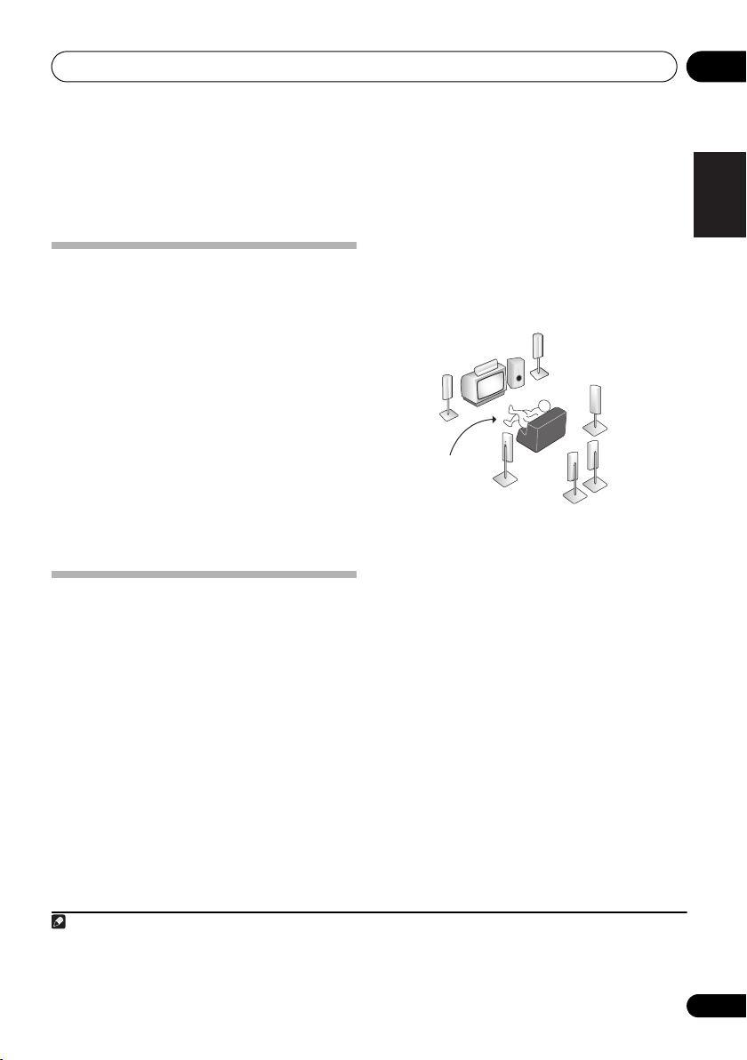
2 Connect your speakers and place them for
optimal surround sound.
See Connecting the speakers on page 19.
Where you place the speakers will have a big
effect on the sound. Place your speakers as
shown below for the best surround sound
effect. Also see Hints on speaker placement on
page 20 for more on this.
Front
speaker
(R)
Subwoofer (SW)
Surround back
speaker (SBL)
Surround
speaker (RS)
Surround
back
speaker (SBR)
Front
speaker
(L)
Listening
position
Center
speaker
(C)
Surround
speaker (LS)
3 Plug in and switch on the receiver,
followed by your DVD player, subwoofer and
TV.
Make sure you’ve set the video input on your
TV to this receiver. Check the manual that
came with the TV if you don’t know how to do
this.
4 Use the on-screen automatic MCACC
setup to set up your system.
See Automatically setting up for surround
sound (MCACC) below for more on this.
5 Play a DVD, and adjust the volume.
Make sure that DVD is showing in the
receiver’s display. If it isn’t, press DVD on the
remote to set the receiver to the DVD input.
1
There are several other sound options you can
select. See Listening to your system on page 28
for more on this.
2
English
Deutsch
Français
Italiano
Nederlands
Español
Note
1 You may need to set your DVD player to output Dolby Digital, DTS and 88.2 kHz/96 kHz PCM (2 channel) audio (see your DVD
player’s manual for more on this).
2 Depending on your DVD player or source disc, you may only get 2 channel sound. In this case, the listening mode must be set
to STANDARD (see Listening in surround sound on page 28 if you need to do this) if you want multichannel surround sound.
7
En
5 minute guide02
Automatically setting up for
surround sound (MCACC)
The Auto Multi-Channel Acoustic Calibration
(MCACC) setup measures the acoustic
characteristics of your listening area, taking
into account ambient noise, speaker size and
distance, and tests for both channel delay and
channel level. After you have set up the
microphone provided with your system, the
receiver uses the information from a series of
test tones to optimize the speaker settings and
equalization for your particular room.
Important
• The Auto MCACC Setup will overwrite any
existing speaker settings you’ve made.
• Make sure the headphones are unplugged.
Caution
• The test tones used in the Auto MCACC
Setup are output at high volume.
INPUT
RECEIVER
AUDIO/VIDEO PRE-PROGRAMMED
REMOTE CONTROL UNIT
F.AUDIO
DVD
CD-R/TAPE
CD
SELECT
TV DVR
XM RADIO
SOURCE
TV CTRL
SIRIUS
RECEIVER
AMFM
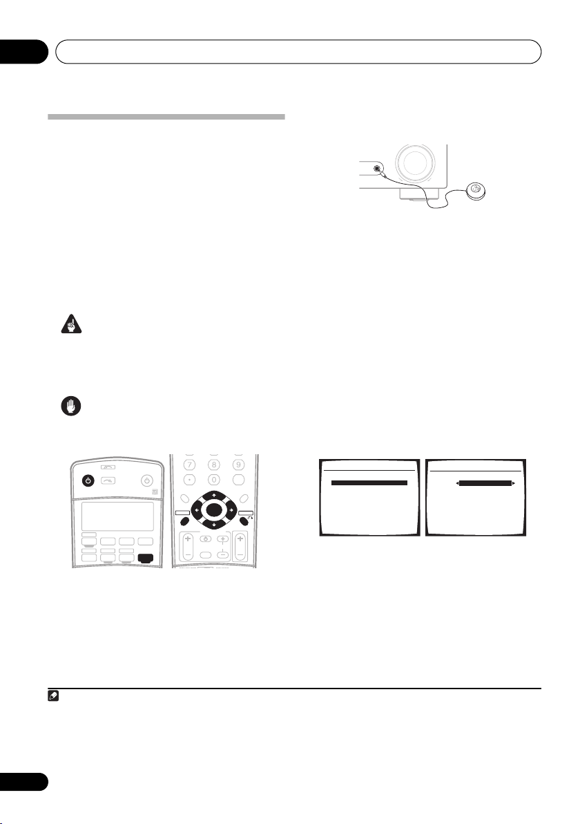
1 Switch on the receiver and your TV.
2 Connect the microphone to the MCACC/
AUDIO IN jack on the front panel.
D.ACCESS
TOP MENU
DTV MENU
SETUP
GUIDE
SIGNAL SEL
+10
ST ST
CATEGORY
TV VOL
TUNE
ENTER
TUNE
TV CONTROL
INPUT
SELECT
CLASS
DISC
ENTER
MENU
T.EDIT
RETURN
TV CH
VOL
Make sure there are no obstacles between the
speakers and the microphone.
MASTER
MCACC/
AUDIO IN
VOLUME
UPDOWN
If you have a tripod, use it to place the
microphone so that it’s about ear level at your
normal listening position. Otherwise, place the
microphone at ear level using a table or a chair.
3 Press
then press the
RECEIVER
SETUP
on the remote control,
button.
An on-screen display (OSD) appears on your
TV. Use /// and ENTER on the remote
control to navigate through the screens and
select menu items. Press RETURN to exit the
current menu.
• Press SETUP at any time to exit the System
Setup menu.
1
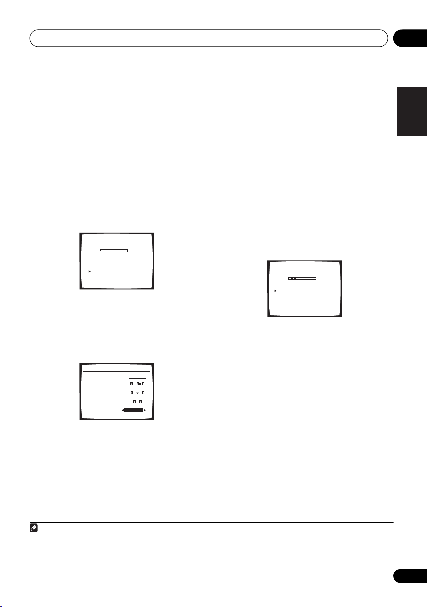
4 Select ‘Auto MCACC’ from the System
Setup menu then press ENTER.
System Setup
1.Surr Back System
2.Auto MCACC
3.Manual MCACC
4.Manual SP Setup
5.Input Assign
6.Other Setup
: Exit
2. Auto MCACC
Surr Back System
Normal (SB) ]
: Cancel ENTER : Start
5 Make sure ‘Normal (SB)’ is selected then
press ENTER.
2
Try to be as quiet as possible after pressing
ENTER. The system outputs a series of test
tones to establish the ambient noise level.
Note
1 • The screensaver automatically starts after three minutes of inactivity. If you cancel the Auto MCACC Setup at any time, the
receiver automatically exits and no settings will be made.
• The OSD will not appear if you have connected using the HDMI output to your TV. Use component, S-video or composite
connections for system setup.
2 If you are planning on bi-amping your front speakers, or setting up a separate speaker system in another room, read through
Surround back speaker setting on page 35 and make sure to connect your speakers as necessary before continuing.
8
En
5 minute guide 02
6 Follow the instructions on-screen.
• Make sure the microphone is connected.
• If you’re using a subwoofer, it is
automatically detected every time you
switch on the system. Make sure it is on
and the volume is turned up.
• See below for notes regarding background
noise and other possible interference.
7 Wait for the test tones to finish.
A progress report is displayed on-screen while
the receiver outputs test tones to determine the
speakers present in your setup. Try to be as
quiet as possible while it’s doing this.
2.Auto MCACC
Now Analyzing
Environment Check
Ambient Noise [ OK ]
Microphone [ ]
Speaker YES/NO [ ]
OK
OK
:Cancel
• For correct speaker settings, do not adjust
the volume during the test tones.
8 Confirm the speaker configuration.
The configuration shown on-screen should
reflect the actual speakers you have.
2.Auto MCACC
Check!
Front [ YES ]
Center [ YES ]
Surround [ YES ]
SB [ Yx2 ]
SUB W. [ YES ]
30:Next
OK
:Cancel
If the speaker configuration displayed isn’t
correct, use / to select the speaker and
/ to change the setting (and number for
surround back). When you’re finished, go to
the next step.
If you see an error message (ERR) in the right
side column, there may be a problem with the
speaker connection. If selecting RETRY
doesn’t fix the problem, turn off the power and
check the speaker connections.
9 Make sure ‘OK’ is selected, then press
ENTER.
If the screen in step 8 is left untouched for 30
seconds, and the ENTER button is not pressed
in step 9 the Auto MCACC setup will start
again from the beginning.
A progress report is displayed on-screen while
the receiver outputs more test tones to
determine the optimum receiver settings for
channel level, speaker distance, and Acoustic
Calibration EQ.
2.Auto MCACC
Now Analyzing
Surround Analyzing
Speaker System [ ]
Speaker Distance [ ]
Channel Level [ ]
Acoustic Cal EQ [ ]
:Cancel
Again, try to be as quiet as possible while this
is happening. It may take 3 to 8 minutes.
10 The Auto MCACC Setup has finished!
Select ‘SKIP’ to go back to the System
Setup menu.
The MCACC indicator on the front panel will
light to show the setup is complete.
The settings made in the Auto MCACC Setup
should give you excellent surround sound
from your system, but it is also possible to
adjust these settings manually using the
System Setup menu (starting on page 35).
1
You can also choose to view the settings by
selecting individual parameters from the
Analyzed Data Check screen:
English
Deutsch
Français
Italiano
Nederlands
Español
Note
1 • Depending on the characteristics of your room, sometimes identical speakers with cone sizes of around 12 cm (5 inches)
will end up with different size settings. You can correct the setting manually using the Speaker Setting on page 41.
• The subwoofer distance setting may be farther than the actual distance from the listening position. This setting should be
accurate (taking delay and room characteristics into account) and generally does not need to be changed.
9
En
5 minute guide02
• Speaker Setting – The size and number of
speakers you’ve connected (see page 41
for more on this)
• Speaker Distance – The distance of your
speakers from the listening position (see
page 43 for more on this)
• Channel Level – The overall balance of
your speaker system (see page 42 for more
on this)
• Acoustic Cal EQ – Adjustments to the
frequency balance of your speaker system
based on the acoustic characteristics of
your room (see page 38 for more on this)
Press RETURN after you have finished
checking each screen. When you’re finished,
select SKIP to go back to the System Setup
menu.
Other problems when using the Auto
MCACC Setup
If the room environment is not optimal for the
Auto MCACC Setup (too much background
noise, echo off the walls, obstacles blocking
the speakers from the microphone) the final
settings may be incorrect. Check for household
appliances (air conditioner, fridge, fan, etc.),
that may be affecting the environment and
switch them off if necessary. If there are any
instructions showing in the front panel display,
please follow them.
• Some older TVs may interfere with the
operation of the microphone. If this seems
to be happening, switch off the TV when
doing the Auto MCACC Setup.
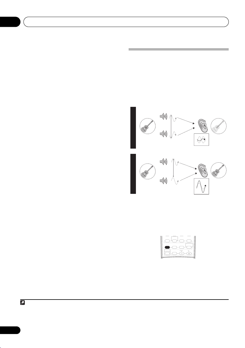
Better sound using Phase
Control
This receiver’s Phase Control feature uses
phase correction measures to make sure your
sound source arrives at the listening position
in phase, preventing unwanted distortion and/
or coloring of the sound (see illustration
below).
P
H
A
S
E
C
O
N
T
R
O
L
Sound
O
source
F
F
P
H
A
S
E
C
O
N
T
R
O
Sound
L
source
O
N
Front speaker
Subwoofer
Front speaker
Subwoofer
Phase Control technology provides coherent
sound reproduction through the use of phase
1
matching
for an optimal sound image at your
listening position. The default setting is on and
we recommend leaving Phase Control
switched on for all sound sources.
STEREO/
AUTO SURR
F.S.SURR
ACOUSTIC EQPHASE
EFFECT/CH SEL LEVEL
SHIFT
STANDARD ADV.SURR
SOUND
DIALOG
RETRIEVER
Listening
position
Listening
position
?
• Press PHASE (PHASE CONTROL) to switch
on phase correction.
Note
1 Phase matching is a very important factor in achieving proper sound reproduction. If two waveforms are 'in phase', they crest
and trough together, resulting in increased amplitude, clarity and presence of the sound signal. If a crest of a wave meets a
trough (as shown in the upper section of the diagram above) then the sound will be 'out of phase' and an unreliable sound image
will be produced.
10
En
Connecting up 03
S
Chapter 3:
Connecting up
Making cable connections
Important
• Before making or changing connections,
switch off the power and disconnect the
power cord from the AC outlet.
• Make sure not to bend the cables over the
top of this unit. If this happens, the
magnetic field produced by the
transformers in this unit may cause a
humming noise from the speakers.
• Before unplugging the power cord, switch
the power into standby.
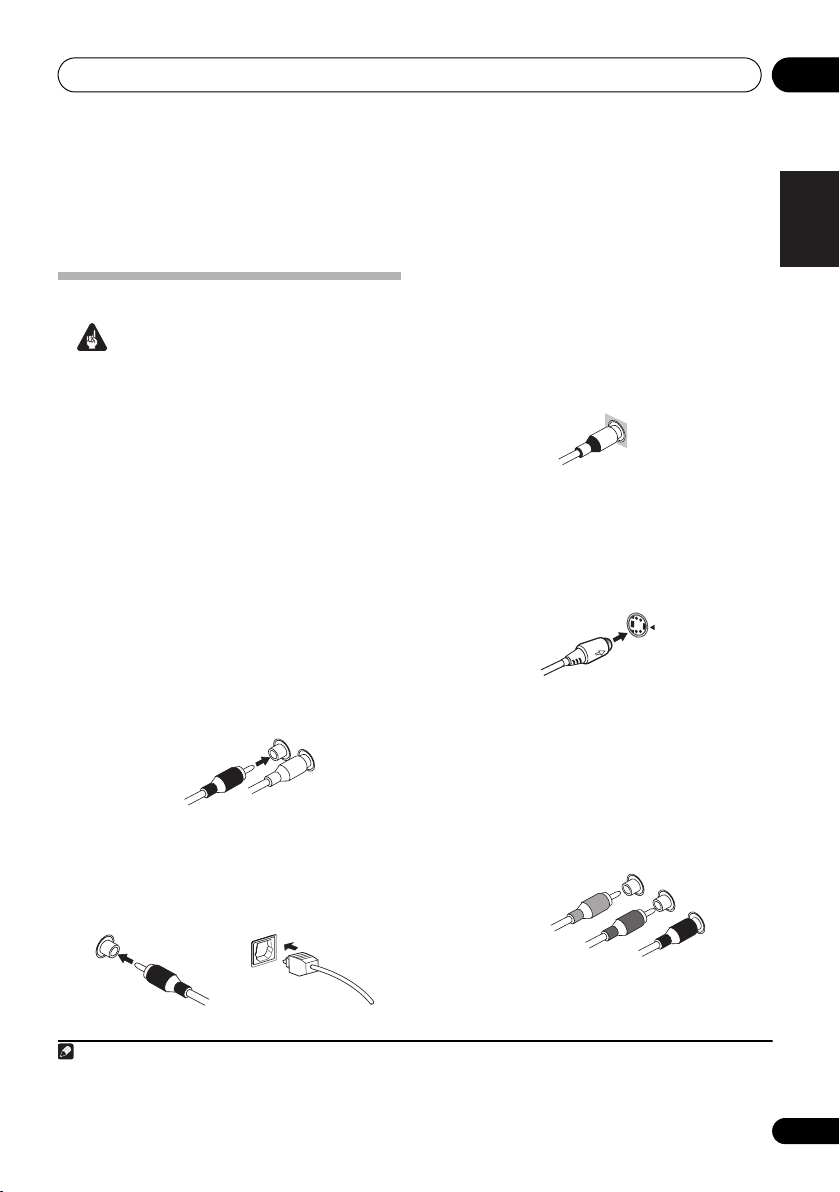
Analog audio cables
Use stereo RCA phono cables to connect
analog audio components. These cables are
typically red and white, and you should
connect the red plugs to R (right) terminals
and white plugs to L (left) terminals.
Analog audio cables
Right (red)
Left (white)
Digital audio cables
Commercially available coaxial digital audio
cables or optical cables should be used to
connect digital components to this receiver.
1
Video cables
Standard RCA video cables
These cables are the most common type of
video connection and are used to connect to
the composite video terminals. The yellow
plugs distinguish them from cables for audio.
tandard RCA video cable
S-video cables
S-video cables give you a clearer picture
reproduction than standard RCA video cables
by sending separate signals for the luminance
and color.
S Video
Component video cables
Use component video cables to get the best
possible color reproduction of your video
source. The color signal of the TV is divided
into the luminance (Y) signal and the color (PB
R) signals and then output. In this way,
and P
interference between the signals is avoided.
Component video cables
Green (Y)
Blue (P
B)
R)
Red (P
English
Deutsch
Français
Italiano
Nederlands
Español
Coaxial digital audio cable Optical cable
Note
1 • When connecting optical cables, be careful when inserting the plug not to damage the shutter protecting the optical socket.
• When storing optical cable, coil loosely. The cable may be damaged if bent around sharp corners.
• You can also use a standard RCA video cable for coaxial digital connections.
11
En
Connecting up03
About the video converter
When the video converter is enabled, all analog
video sources are output through all of the
MONITOR VIDEO OUT jacks (HDMI and highdefinition progressive component video cannot
be converted).
Setup on page 65 to switch the video converter
on or off.
If several video components are assigned to
the same input function (see The Input Assign
menu on page 62), the converter gives priority
to component, S-video, then composite (in that
order).
This product incorporates copyright protection technology
that is protected by U.S. patents and other intellectual
property rights. Use of this copyright protection
technology must be authorized by Macrovision
Corporation, and is intended for home and other limited
consumer uses only unless otherwise authorized by
Macrovision. Reverse engineering or disassembly is
prohibited.
1
See Digital Video Converter
Note
1 You must connect your monitor/TV to the receiver’s HDMI/component video outputs when connecting these video sources. If
the video signal does not appear on your TV or plasma display, try adjusting the resolution settings on your component or display.
Note that some components (such as video game units) have resolutio ns that may not be converted. In this case, use an (analog)
S-video or composite connection.
12
En
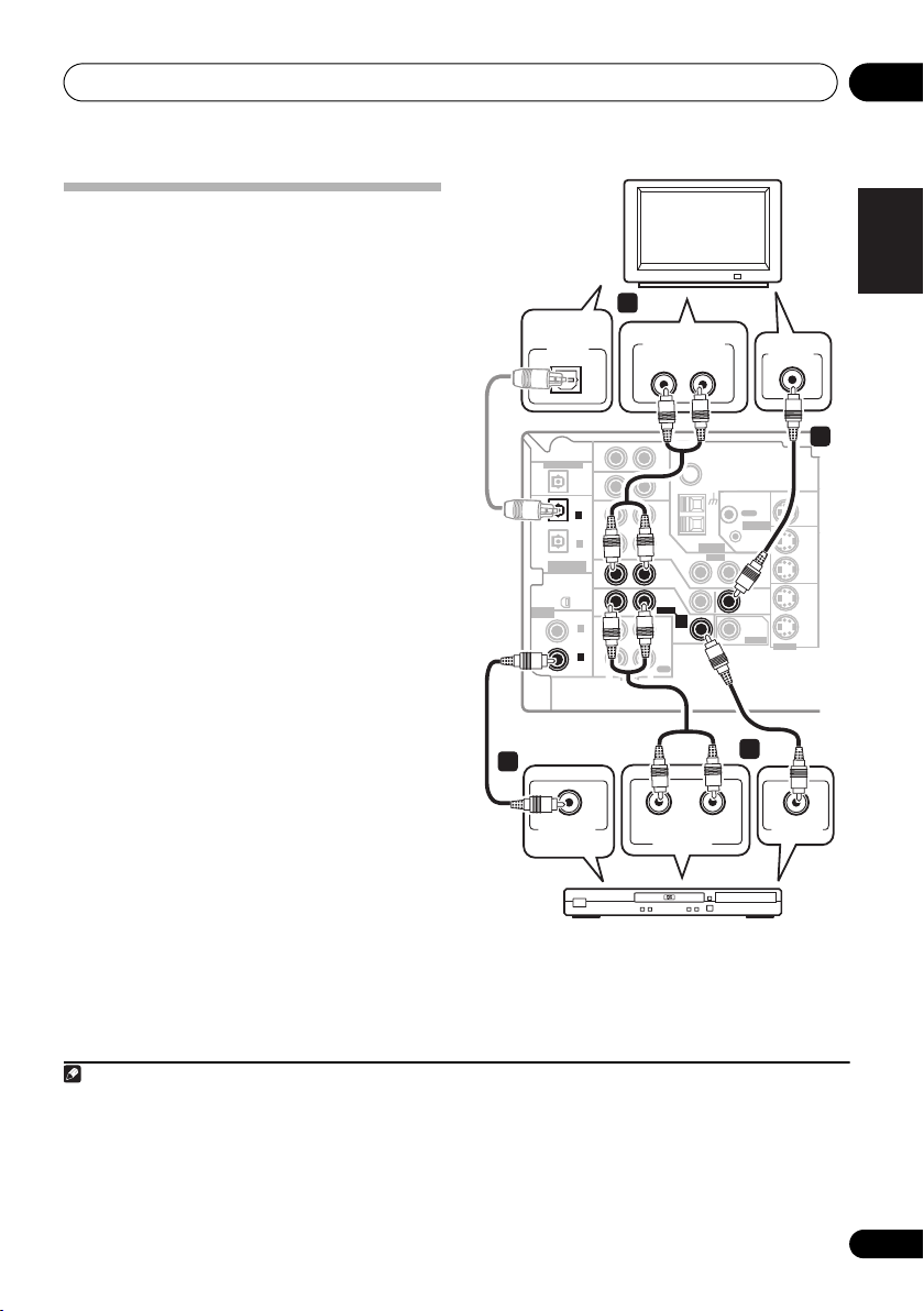
Connecting up 03
Connecting a DVD player and TV
This page shows you how to connect your DVD
player and TV to the receiver.
1 Connect a coaxial digital audio output on
your DVD player to the DIGITAL COAX 1
(DVD/LD) input on this receiver.
Use a coaxial digital audio cable for the
connection.
2 Connect the composite video output and
the stereo analog audio outputs
DVD player to the DVD/LD inputs on this
receiver.
Use a standard RCA video cable3 and a stereo
RCA phono cable for the connection.
• If your DVD player has multichannel
analog outputs, see Connecting the
multichannel analog outputs below for how
to connect it.
3 Connect the analog audio outputs from
your TV to the TV/SAT inputs on this receiver.
This will allow you to play the sound from the
TV's built-in tuner. Use a stereo RCA phono
cable to do this.
•If your TV has a built-in digital decoder, you
can also connect an optical digital audio
output from your TV to the DIGITAL OPT 2
(TV/SAT) input on this receiver. Use an
optical cable for the connection.
4 Connect the MONITOR OUT video jack on
this receiver to a video input on your TV.
Use a standard RCA video cable to connect to
the composite video jack.
1
2
on your
4
DIGITAL
AUDIO OUT
OPTICAL
DIGITAL OUT
(
TV/ SAT
(CD)
ASSIGNABLE
DIGITAL IN
ASSIGNABLE
DIGITAL IN
This receiver
1
COAXIAL
DIGITAL OUT
3
IN
OPT
IN
OPT
2
)
IN
OPT
1
OUT
IN
XM
IN
IN
COAX
2
(
)
DVR/VCR
IN
COAX
1
(
)
DVD/LD
OUT
R
AUDIO
DVD player
ANALOG AUDIO OUT
LR
AUX
CD
DVR/
VCR
LOOP
ANTENNA
IN
TV/
SAT
DVD
IN
/LD
FRONT
D V D
5.1CH
INPUT
PLAY
IN
CD-R
/TAPE
/MD
REC
L
AUDIORL
ANALOG OUT
FM UNBAL
Ω
75
AM
VIDEO
TV
OUT
CONTROL
IN
OUT
MONITOR
OUT
SUB
WOOFER
PREOUT
2
VIDEO IN
MONITOR OUT
IN
S-VIDEO
VIDEO OUT
English
Deutsch
4
Français
OUT
DVR/
VCR
IN
TV/
SAT
IN
DVD
/LD
Italiano
Nederlands
Español
Note
1 If your DVD player only has an optical digital output, you can connect it to the optical input on this receiver using an optical
cable. When you set up the receiver you'll need to tell the receiver which input you connected the player to (see The Input Assign
menu on page 62).
2 This connection will allow you to make analog recordings from your DVD player.
3 For better quality, you can also connect with S-video using the S-VIDEO DVD/LD jack. If your player also has a component
video output, you can connect this too. See Using the component video jacks on page 17 for more on this.
4 For better quality, you can also connect with S-video using the S-VIDEO MONITOR OUT jack. See Using the component video
jacks on page 17 if you want to use the component video outputs to connect this receiver to your TV.
13
En
Connecting up03
T
B
C
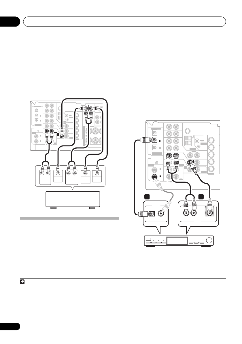
Connecting the multichannel analog
outputs
For DVD Audio and SACD playback, your DVD
player may have 5.1 channel analog outputs.In
this case, you can connect the multichannel
analog outputs to the multichannel inputs of
this receiver as shown below.
This receiver
ASSIGNABLE
DIGITAL IN
DIGITAL OUT
(
TV/ SAT
(CD)
ASSIGNABLE
DIGITAL IN
AUX
IN
OPT
IN
OPT
2
)
IN
OPT
1
OUT
IN
XM
IN
IN
COAX
2
(
)
DVR/VCR
IN
COAX
1
(
)
DVD/LD
OUT
RL RL
FRONT
OUTPUT
FM UNBAL
Ω
75
CD
DVR/
VCR
AM
LOOP
ANTENNA
VIDEO
IN
TV/
SAT
DVD
IN
/LD
FRONT
D V D
5.1CH
INPUT
PLAY
IN
CD-R
/TAPE
/MD
REC
R
L
AUDIO
CENTER
OUTPUT
DVD/multi-channel decoder
with multi-channel analog
output jacks
OUT
CONTROL
IN
OUT
MONITOR
OUT
SUB
WOOFER
PREOUT
SURROUND
OUTPUT
1
CENTER
MONITOR OUT
SURROUND
DVD 5.1CH INPUT
OUT
DVR/
VCR
IN
RL
S
TV/
SAT
P
IN
E
DVD
A
A
/LD
IN
K
S-VIDEO
E
R
S
SUB
WOOFER
OUTPUT
SUB
WOOFER
SIRIUS IN
(
DVR/V
P
Y
LR
MONITOR OU
FRONT
R
VIDEO
OUTPUT
1 Connect a set of audio/video outputs on
the set-top box component to the TV/SAT
AUDIO and VIDEO inputs on this receiver.
2
Use a stereo RCA phono cable for the audio
connection and a standard RCA video cable for
the video connection.
3
2 Connect an optical digital audio output
from your set-top box component to the
DIGITAL OPT 2 (TV/SAT) input on this receiver.
Use an optical cable for the connection.
4
This receiver
DIGITAL OUT
(
TV/ SAT
ASSIGNABLE
DIGITAL IN
OPT
OPT
)
OPT
(CD)
ASSIGNABLE
DIGITAL IN
XM
IN
COAX
(
DVR/VCR
COAX
(
DVD/LD
2
1
2
1
AUX
IN
IN
IN
OUT
IN
IN
)
IN
)
OUT
R
AUDIO
FM UNBAL
Ω
75
CD
DVR/
VCR
LOOP
ANTENNA
IN
TV/
SAT
DVD
IN
/LD
FRONT
D V D
5.1CH
INPUT
PLAY
IN
CD-R
/TAPE
/MD
REC
L
AM
VIDEO
OUT
CONTROL
IN
OUT
MONITOR
OUT
SUB
WOOFER
PREOUT
MONITOR OUT
OUT
IN
IN
IN
S-VIDEO
DVR/
VCR
TV/
SAT
DVD
/LD
2 1
DIGITAL OUT
OPTICAL COAXIAL
Connecting a satellite receiver
L
AV OUT
or other digital set-top box
Satellite and cable receivers, and terrestrial
digital TV tuners are all examples of so-called
`set-top boxes'.
Note
1 The multichannel input can only be used when DVD 5.1 ch is selected (see page 34).
2 If you've already connected your TV to the TV/SAT inputs, simply choose another input. However, to receive a signal, you'll need
to press the input select button for the input you connected the set-top box to.
3 For better quality, you can also connect with S-video using the S-VIDEO TV/SAT jack. If your set-top box also has a component
video output, you can connect this too. See Using the component video jacks on page 17 for more on this.
4 If your satellite/cable receiver doesn’t have a digital audio output, omit this step. If it only has a coaxial digital output, you can
connect it to one of the coaxial inputs on this receiver using a coaxial digital audio cable. When you set up t he receiver you'll need
to tell the receiver which input you connected the set-top box to (see The Input Assign menu on page 62).
14
En
STB
VIDEOAUDIOR
Connecting up 03
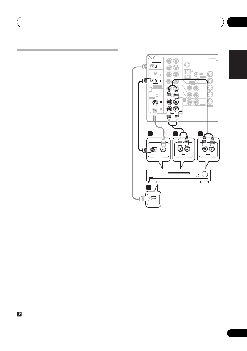
Connecting other audio
components
The number and kind of connections depends
on the kind of component you’re connecting.
Follow the steps below to connect a CD-R, MD,
DAT, tape recorder or other audio component.
1 If your component has a digital output,
connect this to a digital input on the receiver
as shown.
The example shows a coaxial connection to the
CD digital input jack using a coaxial digital
audio cable.
2 If necessary, connect the analog audio
outputs of the component to a set of spare
audio inputs on this receiver.
You’ll need to make this connection for
components without a digital output, or if you
want to record from a digital component. Use a
stereo RCA phono cable as shown.
3 If you're connecting a recorder, connect
the analog audio outputs (REC) to the analog
audio inputs on the recorder.
The example shows an analog connection to
the CD-R/TAPE/MD analog output jack using
a stereo RCA phono cable.
4 If your recorder has a digital input,
connect it to the digital output on the
receiver as shown.
Use an optical cable to make this connection.
This receiver
DIGITAL OUT
OPT
OPT
2
(
)
1
TV/ SAT
ASSIGNABLE
DIGITAL IN
(CD)
ASSIGNABLE
DIGITAL IN
COAX
(
DVR/VCR
COAX
(
OPT
1
XM
IN
DVD/LD
1
OPTICAL COAXIAL
DIGITAL OUT
4
IN
IN
IN
OUT
IN
IN
2
)
IN
1
)
OUT
R
AUDIO
3 2
CD-R, MD, DAT,
AUX
FM UNBAL
Ω
75
CD
DVR/
VCR
AM
LOOP
ANTENNA
VIDEO
IN
TV/
SAT
DVD
IN
/LD
FRONT
D V D
5.1CH
INPUT
PLAY
IN
CD-R
/TAPE
/MD
REC
L
IN
L
R
REC
AUDIO IN
Tape recorder, etc.
OPTICAL
DIGITAL IN
About the WMA9 Pro decoder
This unit has an on-board Windows Media®
Audio 9 Professional (WMA9 Pro) decoder, so
it is possible to playback WMA9 Pro-encoded
audio using a coaxial or optical digital
connection when connected to a WMA9 Procompatible player.
OUT
CONTROL
IN
OUT
MONITOR
OUT
SUB
WOOFER
PREOUT
MONITOR OUT
S-VIDEO
OUT
R
PLAY
AUDIO OUT
English
OUT
DVR/
VCR
IN
TV/
SAT
IN
DVD
/LD
IN
Deutsch
Français
L
Italiano
Nederlands
Español
Note
1 Note that you must connect digital components to analog audio jacks if you want to record to/from digital components (like
an MD) to/from analog components.
15
En
Connecting up03
However, the connected DVD player, set-top
box, etc. must be able to output WMA9 Pro
format audio signals through a coaxial or
optical digital output.
Microsoft, Windows Media®, and the Windows logo are
trademarks, or registered trademarks of Microsoft
Corporation in the United States and/or other countries.
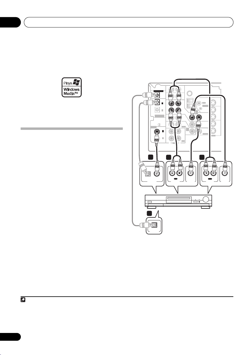
Connecting other video
components
This receiver has audio/video inputs and
outputs suitable for connecting analog or
digital video recorders, including VCRs, DVDrecorders and HDD recorders.
1 Connect a set of audio/video outputs on
the recorder to the DVR/VCR AUDIO and
VIDEO inputs on this receiver.
Use a stereo RCA phono cable for the audio
connection and a standard RCA video cable for
the video connection.
2 Connect a set of audio/video inputs on
the recorder to the DVR/VCR AUDIO and
VIDEO outputs on this receiver.
Use a stereo RCA phono cable for the audio
connection and a standard RCA video cable for
the video connection.
3 Connect a coaxial digital audio output on
your video component to the DIGITAL COAX
2 (DVR/VCR) input on this receiver.
Use a coaxial digital audio cable for the
connection.
3
1
2
4 If your video component has a digital
input, connect it to the digital output on the
receiver as shown.
Use an optical cable to make this connection.
This receiver
DIGITAL OUT
(
TV/ SAT
ASSIGNABLE
DIGITAL IN
3
OPTICAL COAXIAL
DIGITAL OUT
4
OPTICAL
DIGITAL IN
OPT
OPT
)
(CD)
ASSIGNABLE
DIGITAL IN
IN
COAX
(
DVR/VCR
COAX
(
DVD/LD
2
OPT
1
XM
2
1
AUX
IN
IN
IN
OUT
IN
IN
)
IN
)
OUT
R
AUDIO
FM UNBAL
Ω
75
CD
DVR/
VCR
TV/
SAT
DVD
/LD
FRONT
PLAY
CD-R
/TAPE
/MD
REC
L
OUT
CONTROL
AM
LOOP
IN
ANTENNA
VIDEO
OUT
IN
IN
MONITOR
OUT
D V D
5.1CH
SUB
INPUT
WOOFER
IN
PREOUT
1 2
IN
R L
REC
AUDIO IN
VIDEO IN
R L
AUDIO OUT
VCR, DVR, LD player, etc.
MONITOR OUT
S-VIDEO
OUT
PLAY
OUT
DVR/
VCR
IN
TV/
SAT
IN
DVD
/LD
IN
VIDEO OUT
Note
1 For better quality, you can also connect with S-video using the S-VIDEO DVR/VCR IN jack. If your video component also has a
component video output, you can connect this too. See Using the component video jacks on page 17 for more on this.
2 For better quality, you can also connect with S-video using the S-VIDEO DVR/VCR OUT jack.
3 If your video component only has an optical digital output, you can connect it to the optical input on this receiver using an
optical cable. When you set up the receiver you'll need to tell the receiver which input you connected the player to (see The Input
Assign menu on page 62).
16
En
Connecting up 03
T
Using the component video jacks
Component video should deliver superior
picture quality when compared to composite
video. A further advantage (if your source and
TV are both compatible) is progressive-scan
video, which delivers a very stable, flicker-free
picture. See the manuals that came with your
TV and source component to check whether
they are compatible with progressive-scan
video.
Important
• If you connect any source component to
the receiver using a component video
input, you must also have your TV
connected to this receiver's COMPONENT
VIDEO MONITOR OUT jacks.
1 Connect the component video outputs of
your source to a set of component video
inputs on this receiver.
Use a three-way component video cable for the
connection.
2 Assign the component video inputs to the
input source you've connected.
• Since they are assignable, it doesn’t matter
which component video inputs you use for
which source. After connecting everything,
you’ll need to assign the component video
inputs—see The Input Assign menu on
page 62.
3 Connect the COMPONENT VIDEO
MONITOR OUT jacks on this receiver to the
component video inputs on your TV or
monitor.
Use a three-way component video cable.
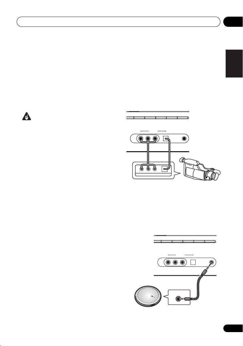
Connecting to the front panel video
terminal
Front video connections are accessed via the
front panel using the VIDEO/FRONT AUDIO
button. Press VIDEO/FRONT AUDIO and
select VIDEO input. There are standard audio/
video jacks as well as an optical input. Hook
them up the same way you made the rear
panel connections.
his receiver
XM
SIRIUS
CD
CD-R/TAPE/MD
FM/AM
VIDEO INPUT
AUDIO RLVIDEO DIGITAL IN
AUX
MCACC/
AUDIO IN
Video
camera
(etc.)
LV
R
VIDEO OUTPUT
DIGITAL OUT
Connecting to the front panel audio
mini jack
Front audio connections are accessed via the
front panel using the VIDEO/FRONT AUDIO
botton. Press VIDEO/FRONT AUDIO and
select F.AUDIO input. Use a stereo mini-jack
cable to connect a digital audio player.
XM
SIRIUS
CD
CD-R/TAPE/MD
FM/AM
VIDEO INPUT
AUDIO RLVIDEO DIGITAL IN
AUX
MCACC/
AUDIO IN
English
Deutsch
Français
Italiano
Nederlands
Español
Portable CD player (etc.)
AUDIO OUT
17
En
Connecting up03
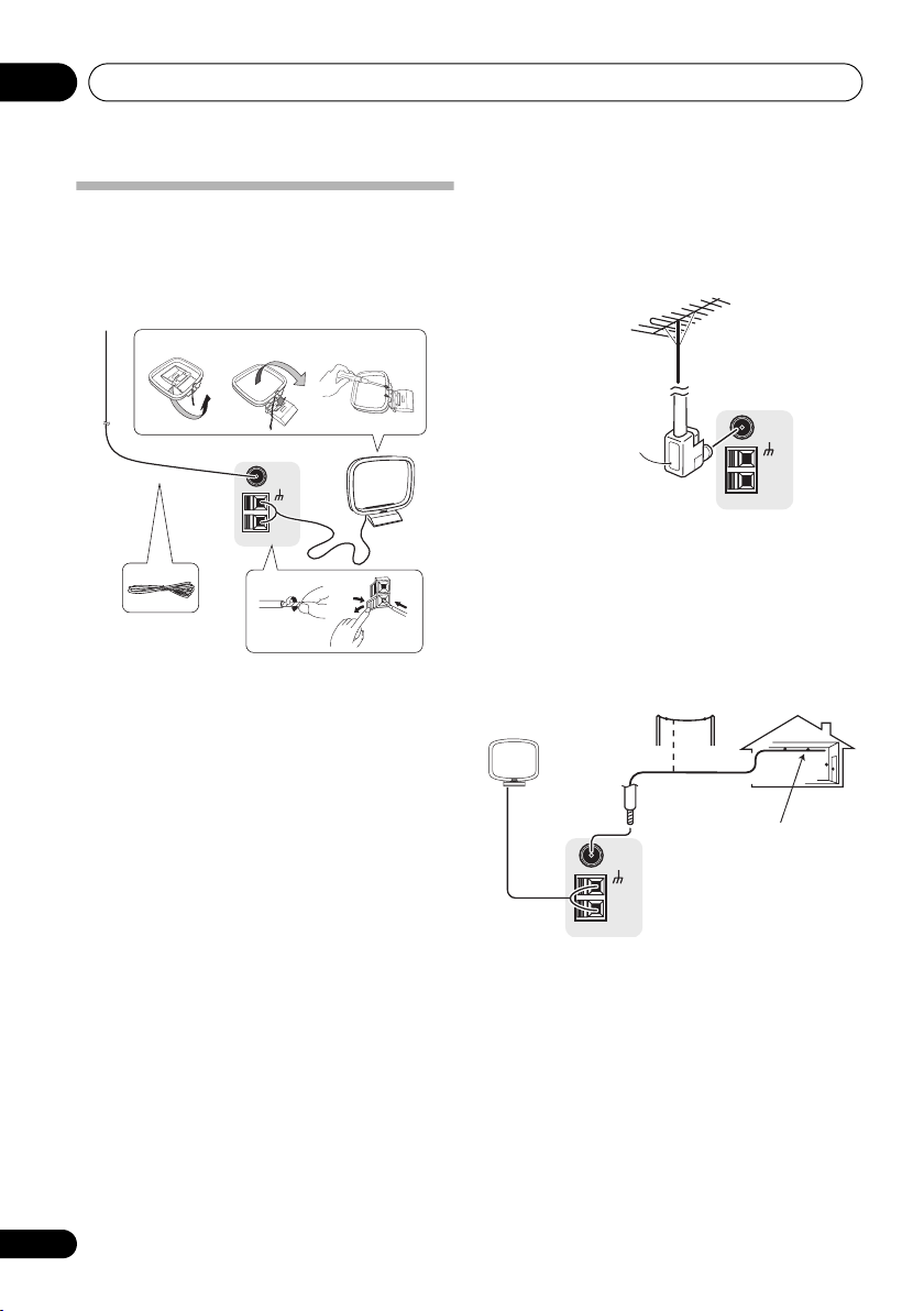
Connecting antennas
Connect the AM loop antenna and the FM wire
antenna as shown below. To improve reception
and sound quality, connect external antennas
(see Using external antennas on page 18).
fig. a fig. b fig. c
FM UNBAL
75
LOOP
1
Ω
AM
5
1 Pull off the protective shields of both AM
antenna wires.
2 Push open the tabs, then insert one wire
fully into each terminal, then release the tabs
to secure the AM antenna wires.
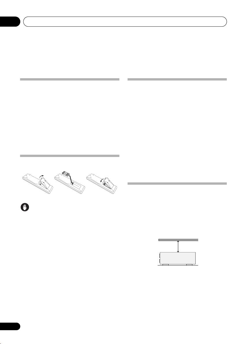
3 Fix the AM loop antenna to the attached
stand.
To fix the stand to the antenna, bend in the
direction indicated by the arrow (fig. a) then
clip the loop onto the stand (fig. b).
• If you plan to mount the AM antenna to a
wall or other surface, secure the stand with
screws (fig. c) before clipping the loop to
the stand. Make sure the reception is clear.
4 Place the AM antenna on a flat surface
and in a direction giving the best reception.
5 Connect the FM wire antenna in the same
way as the AM loop antenna.
For best results, extend the FM antenna fully
and fix to a wall or door frame. Don’t drape
loosely or leave coiled up.
3
4
2
Using external antennas
To improve FM reception
Use an F connector to connect an external FM
antenna.
FM UNBAL
75
AM
LOOP
Ω
F connector
To improve AM reception
Connect a 5 m to 6 m (15 ft. to 18 ft.) length of
vinyl-coated wire to the AM antenna terminal
without disconnecting the supplied AM loop
antenna.
For the best possible reception, suspend
horizontally outdoors.
Outdoor
antenna
5 m to 6 m
(15 ft. to 18 ft.)
FM UNBAL
75
Ω
AM
LOOP
Indoor antenna
(vinyl-coated wire)
18
En
Connecting up 03
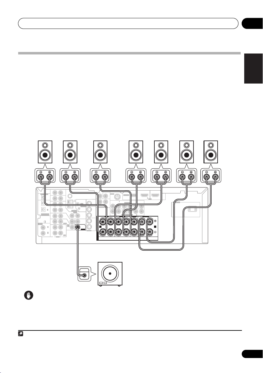
Connecting the speakers
A complete setup of eight speakers (including the subwoofer) is shown here but everyone’s home
setup will vary. Simply connect the speakers you have in the manner shown below.
will work with just two stereo speakers (the front speakers in the diagram) but using at least three
speakers is recommended, and a complete setup is best.
Make sure you connect the speaker on the right to the right terminal and the speaker on the left
to the left terminal. Also make sure the positive and negative (+/–) terminals on the receiver match
those on the speakers.
2
You can use speakers with a nominal impedance between 6 Ω to 16 Ω
(please see Switching the speaker impedance on page 69 if you plan to use speakers with an
impedance of less than 8 Ω).
Front speakers
Center speaker
LR C LSRS
SUB
CEN-
WOOFER
DIGITAL OUT
IN
OPT
IN
OPT
2
(
)
TV/ SAT
IN
OPT
1
OUT
(CD)
ASSIGNABLE
DIGITAL IN
IN
XM
IN
ASSIGNABLE
IN
DIGITAL IN
COAX
2
(
)
DVR/VCR
IN
COAX
1
(
)
DVD/LD
OUT
R
AUDIO
This receiver
AUX
FM UNBAL
75
CD
OUT
CONTROL
DVR/
VCR
AM
LOOP
ANTENNA
VIDEO
OUT
IN
TV/
SAT
DVD
IN
MONITOR
/LD
OUT
FRONT
D V D
5.1CH
SUB
INPUT
PLAY
WOOFER
IN
CD-R
PREOUT
/TAPE
/MD
REC
L
TER
MONITOR OUT
SURROUND
LR
DVD 5.1CH INPUT
IN
OUT
DVR/
VCR
FRONT
IN
RL
S
TV/
SAT
P
IN
E
DVD
A
A B
/LD
IN
K
S-VIDEO
E
R
S
Powered
Surround speakers
SIRIUS IN
ASSIGNABLE
3
IN
ASSIGNABLE
B
P
PR
Y
COMPONENT VIDEO
MONITOR OUT
L
R
(DVD/LD) IN 1
Y
Surround back speakers
SBL SBR
(TV/SAT) IN 2
OUT
HDMI
IN
1
P
B
PR
2
IN
CENTERSURROUND
SURROUND BACK
LR
AC OUTLET
subwoofer
SW
INPUT
1
The receiver
English
Deutsch
Français
Italiano
Nederlands
Español
Caution
• Make sure that all the bare speaker wire is twisted together and inserted fully into the speaker
terminal. Use good quality speaker wire to connect the speakers to the receiver.
Note
1 If you’re not using a subwoofer, change the front speaker setting (see Speaker Setting on page 41) to LARGE.
2 If you are using only one surround back speaker, connect it to the surround back left (L) terminal.
19
En
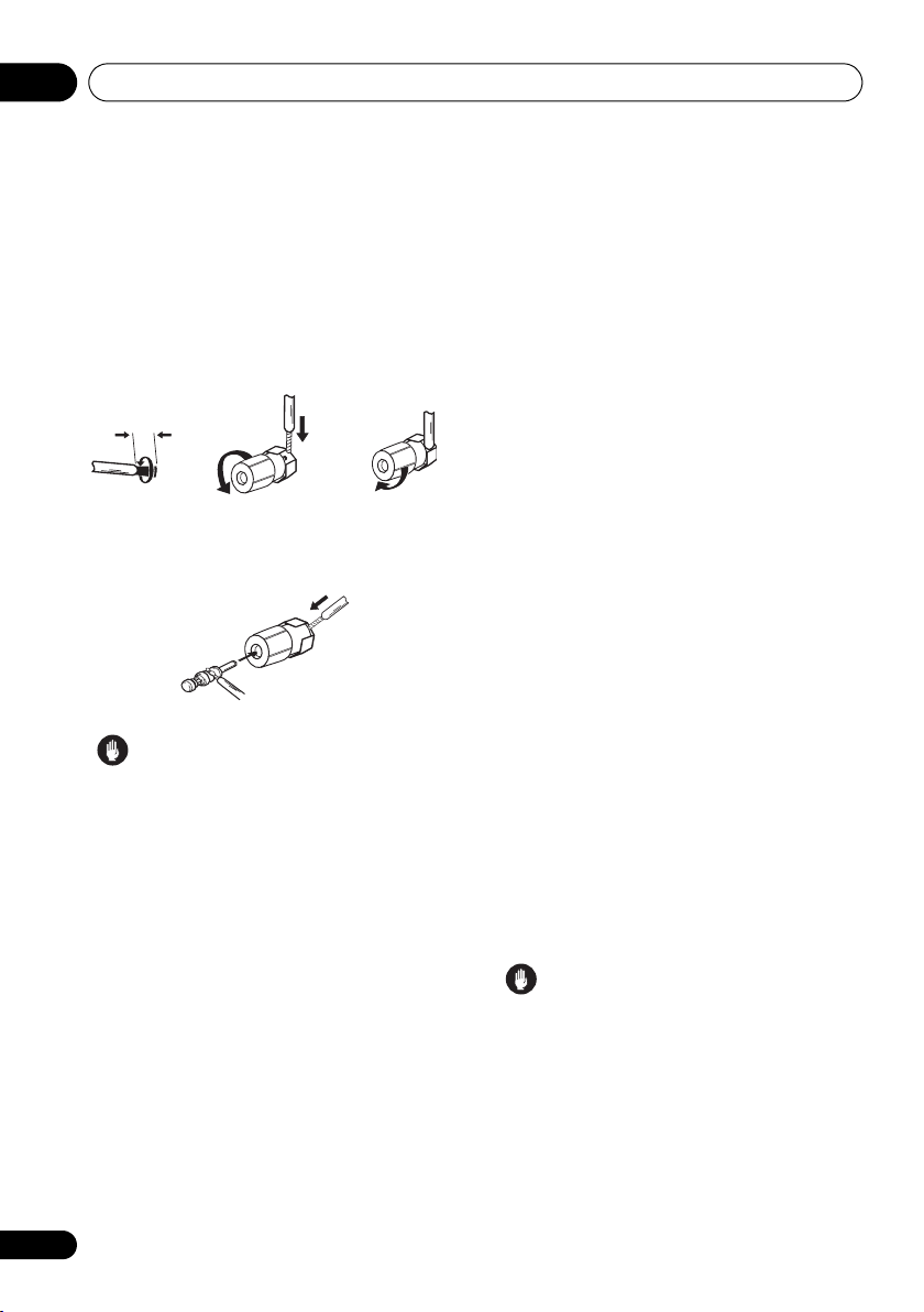
Connecting up03
Make sure that the speaker cable you’re using
3
is properly prepared with about 10 mm (
/8 in.)
of insulator stripped from each wire, with the
exposed wire strands twisted together (fig. A).
Unscrew the terminal a few turns until there is
enough space to insert the exposed wire
(fig. B). Once the wire is in position, tighten the
terminal until the wire is firmly clamped (fig. C).
fig. A fig. B fig. C
10 mm (3/8 in.)
• The speaker terminals also accept single
banana plugs. (Refer to speaker manual for
details.)
Caution
• These speaker terminals are hazardous
when live. To prevent the risk of electric
shock when connecting or disconnecting
the speaker cables, disconnect the power
cord.
Hints on speaker placement
Speakers are usually designed with a
particular placement in mind. Some are
designed to be floorstanding, while others
should be placed on stands to sound their best.
Some should be placed near a wall; others
should be placed away from walls. We have
provided a few tips on getting the best sound
from your speakers (following), but you should
also follow the guidelines on placement that
the speaker manufacturer provided with your
particular speakers to get the most out of
them.
• Place the front left and right speakers at
equal distances from the TV.
• When placing speakers near the TV, we
recommend using magnetically shielded
speakers to prevent possible interference,
such as discoloration of the picture when
the TV is switched on. If you do not have
magnetically shielded speakers and notice
discoloration of the TV picture, move the
speakers farther away from the TV.
• If you're using a center speaker, place the
front speakers at a wider angle. If not, place
them at a narrower angle.
• Place the center speaker above or below
the TV so that the sound of the center
channel is localized at the TV screen. Also,
make sure the center speaker does not
cross the line formed by the leading edge
of the front left and right speakers.
• It is best to angle the speakers towards the
listening position. The angle depends on
the size of the room. Use less of an angle
for bigger rooms.
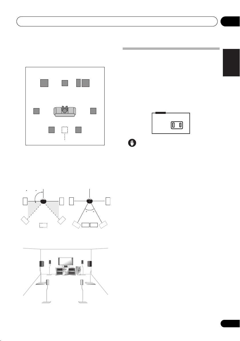
• Surround and surround back speakers
sh ould b e po sitio ned 60 cm t o 90 cm (a f ootand-a-half to three feet) higher than your
ears and titled slightly downward. Make
sure the speakers don't face each other.
• To achieve the best possible surround
sound, install your speakers as shown
below. Be sure all speakers are installed
securely to prevent accidents and improve
sound quality.
Caution
• If you choose to install the center speaker
on top of the TV, be sure to secure it with
putty, or by other suitable means, to reduce
the risk of damage or injury resulting from
the speaker falling from the TV in the event
of external shocks such as earthquakes.
• Make sure no exposed speaker wire is
touching the rear panel, this may cause the
receiver to turn off automatically.
20
En
Connecting up 03
Overhead view of speaker setup
You can also refer to the 3-D speaker setup
illustration on page 7.
Front
left
Surround
left
Listening position
Surround back Surround back
left right
Single surround back speaker
Front
rightCenter
Subwoofer
Surround
right
.
The diagrams below show suggested surround
and surround back speaker orientation. The
first diagram (fig. A) shows orientation with one
surround back speaker (or none) connected.
The second (fig. B) shows orientation with two
surround back speakers connected.
90~120
SBR
RS
SBR
LS
LS
LS
fig. A fig. B
SB
RS
RS
SBL
0~60
SBL
AC outlet
Power supplied through this outlet is turned
on and off by the receiver's power switch. Total
electrical power consumption of connected
equipment should not exceed 100 W (0.8 A).
• This unit should be disconnected by
removing the power plug from the wall
socket when not in regular use (ex. when
on vacation).
AC OUTLET
AC 120 V 60 Hz
SWITCHED 100 W MAX
0.8 A MAX
Caution
• Do not connect a TV set, monitor, heater, or
similar appliance to this unit's AC outlet.
• Do not connect appliances with high
power consumption to the AC outlet in
order to avoid overheating and fire risk.
This can also cause the receiver to
malfunction.
• Since a subwoofer or power amplifier can
exceed the 100 W maximum when playing
sources at a high volume, this type of
equipment should not be connected to the
AC outlet.
English
Deutsch
Français
Italiano
Nederlands
Español
3-D view of
7.1 channel
speaker setup
21
En
Controls and displays04
Chapter 4:
Controls and displays
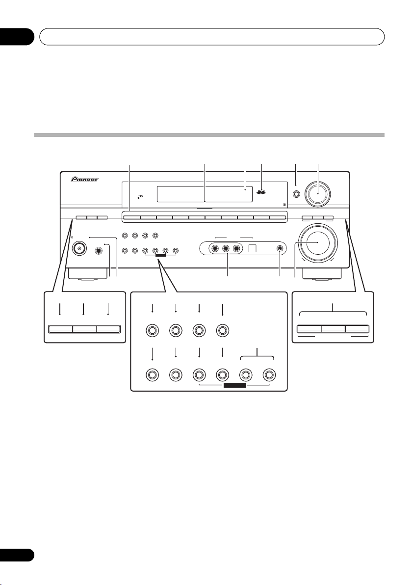
Front panel
32 4
XM
FM/AM
VIDEO INPUT
AUDIO RLVIDEO DIGITAL IN
SIRIUS
AUX
MCACC/
AUDIO IN
CONTROL
STANDBY/ON
1
PHASE
CONTROL
DIGITAL PRECISION
ACOUSTICEQPHASE
AUTO SURR/
PHONES
DVD/LD TV/SAT
DIRECT
MIDNIGHT/
SOUND
LOUDNESS
RETRIEVER
SPEAKERS
DVR/VCR VIDEO/FRONT AUDIO
SB ch
PROCESSING
TONE
TUNING/
TUNER
SIGNAL
STATION
EDIT
SELECT
SETUP RETURN
MULTI JOG
CD
PROCESSING
CD-R/TAPE/MD
5 6
ENTER
STEREO/
F.S.SURR
STANDARD
LISTENING MODE
ADVANCED
SURROUND
VSX-917V
MULTI JOG
MASTER
VOLUME
UPDOWN
910
7 823
ACOUSTIC
PHASE
CONTROL
AUTO SURR/
EQ
DIRECT
14 15
SOUND
RETRIEVER
SPEAKERS
1 Input select buttons
Press to select an input source.
2 Digital Precision Processing indicator
Lights to indicate digital processing.
3 Character display
See Display on page 23.
4 MCACC indicator
Lights when Acoustic Calibration EQ (page 31)
is on (Acoustic Calibration EQ is automatically
set to ALL CH ADJUST after the Auto MCACC
Setup (page 8) or EQ Auto Setup (page 38)).
5
ENTER
6
MULTI JOG
dial
Use the MULTI JOG dial to select various
settings and menu options.
22
En
MIDNIGHT/
LOUDNESS
SIGNAL
SELECT
131211
16 17
SB ch
PROCESSING
TUNING/
STATION
TONE
2118 19 20 22
TUNER
EDIT
SETUP RETURN
MULTI JOG
STEREO/
F.S.SURR
LISTENING MODE
7PHASE CONTROL
Press to switch on/off Phase Control (page 10).
8 ACOUSTIC EQ
Press to select an Acoustic Calibration EQ
setting (page 31).
9
PHONES
jack
Use to connect headphones (when connected,
there is no sound output from the speakers).
10
STANDBY/ON
Switches the receiver between on and standby.
11
VIDEO INPUT
See Connecting to the front panel video terminal
on page 17.
23
STANDARD
ADVANCED
SURROUND
Controls and displays 04
12 MCACC/
AUDIO
IN jack
Use to connect a microphone when performing
Auto MCACC setup, or connect an auxiliary
component using a stereo mini-jack cable
(page 17).
13
MASTER VOLUME
dial
14 SOUND RETRIEVER
Press to restore CD quality sound to
compressed audio sources (page 33).
15
MIDNIGHT/LOUDNESS
Switches between Midnight and Loudness
listening (page 32).
16
SB ch PROCESSING
Selects surround back channel processing
(page 31) or the virtual surround back mode
(page 32).
17
TONE
Press this button to access the bass and treble
controls, which you can then adjust with the
MULTI JOG dial (page 33).
18
SPEAKERS
Use to change the speaker system (page 59)
and the impedance setting (page 69).
19
SIGNAL SELECT
Use to select an input signal (page 33).
20
TUNING / STATION
Selects the frequency (page 44) and station
presets (page 44) when using the tuner.
21
TUNER EDIT
Press to memorize and name a station for
recall (page 44).
22 System Setup menu controls
SETUP – Use with the MULTI JOG dial to
access the System Setup menu (page 8,
page 35, page 62).
RETURN – Press to confirm and exit the
current menu.
23
LISTENING MODE
buttons
AUTO SURR/DIRECT
Selects Auto Surround (Auto playback on
page 28) or Stream Direct playback
(page 30). Also when listening to XM
Radio, AUTO SURR selects XM HD
Surround feature (page 54).
STEREO
/F.S.SURR
– Switches between
stereo playback and Front Stage Surround
Advance modes (page 30).
STANDARD – Press for Standard decoding
and to switch between the various Pro Logic
IIx and Neo:6 options (page 28).
ADVANCED SURR – Use to switch
between the surround modes (page 29).
English
Deutsch
Français
Italiano
Nederlands
Español
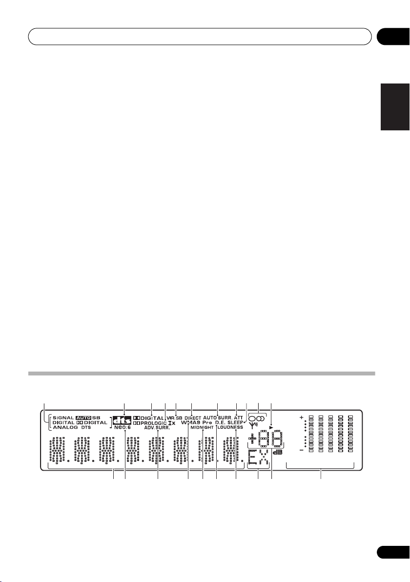
Display
1234567118910
12
1
SIGNAL
indicators
Lights to indicate the type of input signal:
AUTO – Lights when AUTO signal select is
on.
1615 17 1813 14 19 20 21
SB – Depending on the source, this lights
when a signal with surround back channel
encoding is detected.
[]
6
L
[]
C
[]
R
SP
AB
[]
Rs
0
[ ]
SB
R
[]
SB
L
[]
Ls
6
40
125
250 4K
13K
23
En
 Loading...