


AUDIO/VIDEO MULTI-CHANNEL RECEIVER
AUDIO-/VIDEO- MEHRKANAL-RECEIVER
VSX-C550
Operating Instructions
Bedienungsanleitung

2
En
Thank you for buying this Pioneer product.
Please read through these operating instructions so you will know how to operate your model properly. After you have finished reading the instructions, put them away in a safe place for future reference.
In some countries or regions, the shape of the power plug may sometimes differ from that shown in the explanatory drawings. However, the method of connecting and operating the unit is the same.
This product complies with the Low Voltage Directive (73/23/EEC, amended by 93/68/EEC), EMC Directives (89/336/EEC, amended by 92/31/EEC and 93/68/EEC).
CAUTION:
THE STANDBY/ON BUTTON IS SECONDARY CONNECTED AND THEREFORE DOES NOT SEPARATE THE UNIT FROM MAINS POWER IN STANDBY POSITION. THEREFORE INSTALL THE UNIT SUITABLE PLACES EASY TO DISCONNECT THE MAINS PLUG IN CASE OF THE ACCIDENT. THE MAINS PLUG OF UNIT SHOULD BE UNPLUGGED FROM THE WALL SOCKET
WHEN LEFT UNUSED FOR A LONG PERIOD OF TIME. H017BEn
This product is for general household purposes. Any failure due to use for other than household purposes (such as long-term use for business purposes in a restaurant or use in a car or ship) and which requires repair will be charged for even during the warranty period.
Operating Environment H045 En
Operating environment temperature and humidity:
+5°C – +35°C (+41°F – +95°F); less than 85%RH (cooling vents not blocked)
Do not install in the following locations
• Location exposed to direct sunlight or strong artificial light
• Location exposed to high humidity, or poorly ventilated location
VENTILATION: When installing this unit, make sure to leave space around the unit for ventilation to improve heat radiation (at least 20 cm at top, 50 cm at rear, and 10 cm at each side).
WARNING: Slot and openings in the cabinet are provided for ventilation and to ensure reliable operation of the product and
to protect it from overheating, to prevent fire hazard, the openings should never be blocked and covered with items, such as newspapers, tablecloths, curtains, etc. Also do not put the apparatus on the thick carpet, bed, sofa, or fabric having a thick pile.
H040 En
Features
Compatibility with the Home Theater Formats
Dolby Digital, DTS Sound Decoders
These highly evolved multichannel sound formats are the heart of home theater. They deliver realistic multichannel sound that can turn any living room into a theater, reproducing all the sound effects of the original movie. The VSX-C550 has the flexibility to decode all these formats.
Dolby Pro Logic II Decoder
The VSX-C550 reproduces this industry-leading format with excellent clarity. With it you can get multichannel surround sound even from two channel and Dolby Surround sources.
Easy-to-use Remote Control
This new remote control is extremely convenient to use. One button is dedicated to one task in the control of the receiver, eliminating confusing buttons whose purpose are unclear. In addition, this remote can be used to operate a variety of other components simply by recalling the appropriate setup codes.
Easy Setup for Quick Home Use
This receiver features an automatic setup function that senses which speakers you have hooked up and automatically sets the receiver for proper surround sound. Thus, you can start enjoying home theater immediately after hooking up your speakers and components, without worrying about difficult setup procedures.
Home Theater Listening Modes
Custom Designed Listening Modes (p.33)
These modes enhance the sound of sources from movies and music to TV and video games for a more dramatic effect. These are each designed to accentuate specific sound qualities, giving the listener a wide range of possibilities.
VIRTUAL Mode (p.33)
This especially designed listening mode uses only two channels but through sound imaging imitates a full surround sound. It allows you to experience surround sound with only two speakers.
PHONES SURROUND Mode (p.33)
This new headphone mode allows the user to get a surround-like sound while listening on headphones designed to accommodate this technology.
Sound Modes (p.35)
This unit also has especially created Sound Modes that can enhance your listening experience and bring out the best in each soundtrack. Each mode is designed to bring out a specific quality of the soundtrack or balance the sound. The NATURAL corrects the frequencies for small speakers to achieve better theater-like surround sound. The MIDNIGHT listening mode allows you to obtain excellent surround sound effects even when listening at low volumes, something that was previously impossible. The QUIET mode provides good sound by smoothing out harsh noises in the soundtrack. This is achieved by reducing the bass and treble. The BRIGHT mode flattens out the total frequency output to match the charactersics of the front speakers. The S.BASS mode gives you added bass for that driving punch that really livens up your music or makes a film more realistic.
The Energy-saving Design
This unit is designed to use less than 1 W of energy when the receiver is in standby mode.
Manufactured under license from Dolby Laboratories. "Dolby", "Pro Logic", and the double- D symbol are trademarks of Dolby Laboratories.
“DTS” and “DTS Digital Surround” are trademarks of Digital Theater Systems, Inc.
TruSurround and ® symbol are trademarks of SRS Labs, Inc. TruSurround technology is incorporated under license from SRS Labs, Inc.
English
3
En

Contents
Congratulations on buying this fine Pioneer product.
Please read through these operating instructions so you will know how to operate your model properly. After you have finished reading the instructions, put them away in a safe place for future reference.
|
Contents |
|
4 |
|
|
|
|
|
|
|
|
|
|
Quick Start Guide |
|
5 |
|
|
|
|
|
|
|||
01 |
Introductory Information |
9 |
|
|
|
|||||||
|
Checking the Supplied Accessories |
9 |
|
|
||||||||
|
Installing the Receiver |
9 |
|
|
|
|
|
|
||||
|
Ventilation |
9 |
|
|
|
|
|
|
|
|
|
|
|
When Making Cable Connections |
9 |
|
|
||||||||
|
Loading the Batteries |
|
10 |
|
|
|
|
|
|
|||
|
Operating Range of Remote Control Unit |
10 |
|
|||||||||
|
Maintenance of External Surfaces |
10 |
|
|
||||||||
02 |
Connecting Your Equipment |
11 |
|
|
||||||||
|
Audio/Video Cords |
11 |
|
|
|
|
|
|
||||
|
Coaxial Cords/Optical Cables |
11 |
|
|
|
|||||||
|
Connecting a DVD Player & TV |
12 |
|
|
|
|||||||
|
Connecting a Digital Tuner/Set Top Box |
13 |
|
|||||||||
|
Connecting a TV with an Internal Digital Tuner |
14 |
||||||||||
|
Connecting Video Components |
14 |
|
|
|
|||||||
|
Connecting Speakers |
|
16 |
|
|
|
|
|
|
|||
|
Hints on Speaker Placement |
17 |
|
|
|
|
||||||
|
Connecting Antennas |
|
18 |
|
|
|
|
|
|
|||
|
Using External Antennas |
18 |
|
|
|
|
|
|||||
|
Operating other Pioneer Components with this |
|
||||||||||
|
Unit’s Sensor |
|
19 |
|
|
|
|
|
|
|
|
|
|
Plugging in the Receiver |
19 |
|
|
|
|
|
|||||
03 |
Displays & Controls |
20 |
|
|
|
|
|
|||||
|
Front Panel |
|
20 |
|
|
|
|
|
|
|
|
|
|
Rear Panel |
21 |
|
|
|
|
|
|
|
|
|
|
|
Remote Control |
22 |
|
|
|
|
|
|
|
|
||
04 |
Basic Playback |
24 |
|
|
|
|
|
|
|
|||
|
Checking the Settings on Your DVD (or other) |
|
||||||||||
|
Player 24 |
|
|
|
|
|
|
|
|
|
|
|
|
Program Format/Speaker Channel Indicators |
24 |
||||||||||
|
Playing a Source |
25 |
|
|
|
|
|
|
|
|
||
05 |
Fine Tuning Your Surround Sound |
26 |
|
|||||||||
|
Room Setup |
|
26 |
|
|
|
|
|
|
|
|
|
|
Personalizing |
Your Surround Sound |
27 |
|
|
|||||||
|
Setting the Volume Level of Each Channel |
32 |
|
|||||||||
06 |
Playback Modes |
33 |
|
|
|
|
|
|
||||
|
Listening Modes |
33 |
|
|
|
|
|
|
|
|
||
|
Selecting a Listening Mode |
34 |
|
|
|
|
||||||
4 |
Sound Modes |
35 |
|
|
|
|
|
|
|
|
|
|
|
|
|
|
|
|
|
|
|
|
|
|
|
Selecting a Sound Mode 35
07 Using the Tuner |
36 |
|
|
|
Finding a Station 36 |
|
|
||
MPX Mode |
36 |
|
|
|
RF ATT Mode 36 |
|
|
|
|
Tuning Directly to a Station |
37 |
|||
Memorizing Stations |
37 |
|
||
Naming Memorized Stations |
38 |
|||
Recalling Memorized Stations |
38 |
|||
An Introduction to RDS |
39 |
|
||
Using the RDS Display |
39 |
|
||
Searching for RDS Programs |
40 |
|||
An Introduction to EON |
41 |
|
||
The Receiver’s Internal Program |
||||
Identification Function |
41 |
|
||
Using EON |
42 |
|
|
|
08 Using Other Functions 43 |
|
Muting the Sound |
43 |
Using the Headphones 43 |
|
Changing the Display Brightness (DIMMER |
|
button) 43 |
|
Input Signal Select |
44 |
The SLEEP Function |
44 |
Resetting the System |
44 |
Default Settings for the Receiver 45 |
|
09 Controlling the Rest of Your System 46
Changing the Remote Control Mode 46
Recalling Preset Codes 47
Clearing the Preset Codes 48
CD/MD/CD-R/VCR/DVD/LD/DVD recorder/ Cassette Deck Controls 49
Cable TV/Satellite TV/Digital TV/TV Controls 50
Preset Code List 51
10Additional Information 54
Troubleshooting 54
11 Techno Know How |
57 |
|
Understanding DVD Packaging 57 |
||
Digital Audio Formats |
57 |
|
Recording Formats |
58 |
|
Playback Formats |
58 |
|
Specifications 59 |
|
|
En

Quick Start Guide
Home Theater: The Basics
Most consumers are used to using stereo equipment to listen to music but many people are not used to home theater systems that give you many more options when listening to soundtracks. In fact, home theater is not really complicated and this little guide should give you an understanding of basics.
The main reasons why it seems so difficult is that there are three different factors involved in home theater and each will contribute to what kind of sound you get.
These factors are:
1)The equipment you are using for you home theater set up. Particularly important is the number of speakers you are using. We call this your speaker configuration. The default settings should be fine in most cases.
2)The 'source' material you are using. This is the actual product (like a DVD) or broadcast (like cable TV) you are listening to/watching. We call this the source.
3)The last factor is the listening mode you choose on the VSX-C550 receiver. These are explained below and in subsequent chapters but most likely the default setting will be fine.
Let's start with the home theater set up you have in your home.
Your Home System
The heart of your system is the VSX-C550 receiver and it is very flexible in getting you theater-like surround sound. You can use this receiver with anywhere from two to five speakers (front left, front right, center, surround left and right) and a subwoofer to get home theater surround sound. However we recommend you use five speakers. If you only have two speakers choose the Listening mode that offers surround sound for your home setup. Also, a DVD player is essential for home theater and you can also hook up satellite or cable TV tuner to this receiver and get a more home theater like sound from those programs.
The Source Material
DVDs have become the basic source material for home theater because they offer excellent sound and picture quality, allow users to choose the movies they want, and are easy to store, etc. You can also enjoy home theater with other sources, such as digital satellite TV, cable TV and VHS videotapes. The important part here is all these sources have soundtracks recorded on them with various kinds of technology (this is called the sound encoding). Home theater sources are recorded (encoded) with multiple sound channels, that is discrete parts of the overall sound. CDs (which are stereo sources) work the same way but they only have two sound channels, the left channel and the right channel. These two channels carry different parts of the soundtrack and mix together when you hear it to make an enjoyable, stereo sound. The same idea applies to home theater sources except home theater sources are recorded with multichannels, that is, more than two channels. For example, Dolby Pro Logic encoding has four channels (front left, front right, center and a single channel for both surround speakers), Dolby Pro Logic II, Dolby Digital and DTS encoding usually have six channels (front left, front right, center, surround left and right and a channel that powers the subwoofer). Since the subwoofer channel is only for bass sounds this multichannel set up has been named 5.1 channel sound. These multiple channels are what create a surround sound effect and give you a similar experience of that of a movie theater. It is important you consult the manual that came with your DVD player as well to make sure the player is outputting a surround soundtrack and all the other settings are appropriate for home theater.
The Listening Modes
This receiver has many different listening modes and they are designed to cover all the speaker configurations and types of sources you might be using. In general, if you follow the recommend advice and have five speakers hooked up in most cases the AUTO listening mode is the easiest way to get realistic home theater sound. This is the default setting so you don't have to do anything. Other possibilities (like listening to a stereo CD with all five speakers or, conversely taking a stereo source and it getting multichannel home theater-like sound) are explained in Listening modes (page 33).
These are the three basic factors that contribute to your home theater sound. The easiest thing is to hook up five speakers and simply play your DVDs with AUTO mode. This will give you realistic and enjoyable home theater sound.
English
5
En
Quick Start Guide
No Frills Setup
This receiver was designed with the easiest possible setup in mind so if you just want to hook up your equipment and start enjoying quality home theater movies follow the four steps below and use these easy settings on the VSX-C550. In most cases you can leave the receiver in the default settings.
Default Settings:
•Speaker Setting: Automatically sensed by the receiver
•Input Setting: DVD
•Signal Select: AUTO
•Listening Mode: AUTO
•Sound Mode: NATURAL
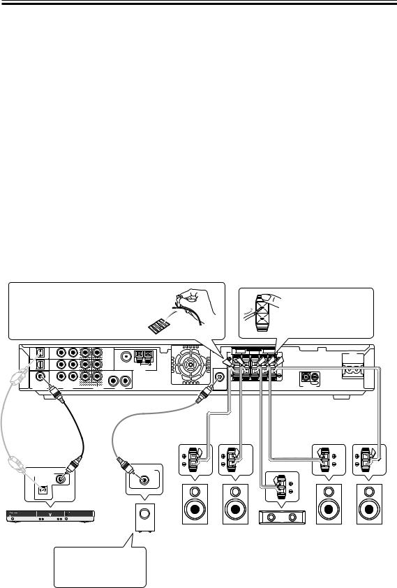
1) Hook up your DVD player, speakers, subwoofer and TV.
Connect your DVD player to this unit using either the coaxial digital terminal or the optical digital terminals, depending on which type of digital terminal your DVD has. The quality of these two types of connection is the same so it’s simply a matter of matching like with like, and you don’t need to do both. It is easiest, however, if you follow this receiver’s default settings and connect your DVD player to coaxial terminal. If your DVD player does not have an coaxial terminal, use one of the optical terminal to hook it up to this receiver. (In this case you need to assign the DVD function to that terminal. See p.31 in order to do this.) Follow the diagram below to hook up your DVD player to either the coaxial or optical terminal(s). Then, hook up the speakers you want to use with this receiver. This receiver can be used with just two speakers but it’s better to have five speakers to get accurate surround sound. See pages 16-17 for more details on connecting your speakers. Next, hook up your powered subwoofer, if you have one. For all speakers make sure to connect the positive (+) and negative (–) terminals on the receiver and speakers with the same wire (positive to positive, negative to negative).
Before hooking up your speakers affix the color-coded sticker with the appropriate name (for example, “FRONT R”) to the speaker wire so you always know which speaker that wire is connected to.
While pressing down the speaker tab push the speaker wire into the terminal and release speaker terminal tab.
DVR/ |
DVR/ |
|
OUT |
F M UNBAL75 Ω |
VCR |
VCR |
|
2 |
|
OPT2 |
IN |
|
|
AM LOOP |
|
|
|
ANTENNA |
|
|
|
|
|
|
DVD |
DVD |
|
R |
L |
(TV/ |
|
DVR/ |
|
|
SAT) |
IN |
|
|
|
|
|
VCR |
|
|
COA X |
|
|
|
|
R |
L |
OUT |
|
|
|
|
|||
DIGITAL IN |
|
AUDIO |
VIDEO |
AUDIO |
|
FRONT |
SPEAKERS |
SURROUND |
|
AC IN |
R |
|
L CENTER R |
|
L |
|
SUB |
|
|
|
IN |
OUT |
WOOFER |
|
|
|
CONTROL |
|
OUT |
|
|
|
|
|
Optical cable |
Coaxial cable |
|
|
(sold separately) |
|
||
(sold sepa- |
|
||
Audio cord |
Speaker wire |
||
rately, don’t |
|||
(sold separately) |
(sold separately) |
||
pinch or bend |
|||
|
|
||
cable sharply) |
|
|
LINE LEVEL
DIGITAL AUDIO OUT
COAXIAL
OPTICAL
DVD Player |
Front R |
(DV-550, etc.) |
|
When you’re hooking up |
(R) |
|
|
your subwoofer make |
Powered |
sure its power cord is |
|
disconnected. |
Subwoofer (SW) |
Front L |
Center |
Surround R |
Surround L |
(L) |
(C) |
(RS) |
(LS) |
If you only hook up two speakers set the Listening mode to one of the modes for two channel outputs.
6
En
Quick Start Guide
Video cord (sold separately)
TV/ |
TV/ |
|
1 |
|
SAT |
SAT |
|
|
|
(DVD) |
IN |
|
|
|
OPT1 |
|
MONITOR |
|
|
|
|
|
||
DVR/ |
DVR/ |
|
OUT |
F M UNBAL75 Ω |
VCR |
VCR |
|
2 |
|
OPT2 |
IN |
|
|
AM LOOP |
|
|
|
ANTENNA |
|
|
|
|
|
|
DVD |
DVD |
|
R |
L |
(TV/ |
|
DVR/ |
|
|
SAT) |
IN |
|
|
|
|
|
VCR |
|
|
COA X |
|
|
|
|
R |
L |
OUT |
|
|
|
|
|||
DIGITAL IN |
|
AUDIO |
VIDEO |
AUDIO |
|
FRONT |
SPEAKERS |
SURROUND |
|
AC IN |
R |
|
L CENTER R |
|
L |
|
SUB |
|
|
|
IN |
OUT |
WOOFER |
|
|
|
CONTROL |
|
OUT |
|
|
|
|
|
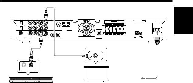
Video cord
(sold separately) |
MONITOR IN |
|
S
VIDEO OUT
DVD Player |
|
To wall |
|
TV |
outlet |
||
(DV-550, etc.) |
|||
|
|
Power cord |
Lastly, hook up your DVD player to the DVD IN VIDEO and your TV to the MONITOR OUT VIDEO terminals as shown above and plug in the receiver’s power cord to a power outlet.
Automatic speaker setup (receiver automatically configures Front, Center, Surround speakers and Subwoofer)
Once you have completed the above tasks, the receiver will automatically detect which speakers you have connected and configure your speaker settings according to that. You don’t have to do anything. This setup establishes the size and configuration of the speaker system you have connected and is the easy way to setup your speakers for surround sound. If you don’t have surround speakers or want to make more exact speaker settings, go to page 27.
The Automatic speaker setup will give you acceptable surround sound.
English
2) Turn on the power on the receiver, your DVD player, your powered subwoofer and TV.
• Make sure your TV is set to the receiver. If it is not, check the input jack this receiver is hooked up to on your TV and consult the manual that came with the TV to figure out the proper TV setting.
• Confirm that DVD appears in the receiver’s display, indicating that the receiver is set to the DVD input. If it does not, press the DVD button to set the receiver to DVD input.
3) Confirm the settings on your DVD player are correct for the source you want to play.
Make sure your DVD player is outputting a digital signal and choose the soundtrack (Dolby Digital, DTS, etc.) that you want to hear. If you are unsure about your DVD player’s settings, see page 24 for more information and/or consult the manual that came with your DVD player.
4) Play a source (like a DVD) and adjust the volume to your liking.
You are now ready to experience home theater with your new surround sound system.
7
En

Quick Start Guide
Advanced/Customized Settings
If you want to customize your home theater to your environment, equipment or personal tastes, many settings are available. One of the most important advanced settings, called Room Setup, establishes the distances between your speakers and your normal listening position (as well as volume levels, etc.). Making this setting should improve your surround sound. Room Setup is explained on page 26. After that you could go on to fine tune your surround sound for maximum sound quality. These settings start on page 27.
The VSX-C550 has many different listening modes to accommodate many different kinds of sources, speaker configurations and sound reproduction. Experiment with these features to figure out what suits your tastes. The listening mode explanations and settings start on page 33.
The above is a quick guide to getting you started with your home theater system and a few setup suggestions. It is a good idea, however, to read this manual in its entirety so you understand what you can do with the VSX-C550 and the possibilities of home theater in general. You may find many hints in these explanations that help you get better sound and let you operate all your equipment more effectively.
8
En
Introductory Information
Checking the Supplied
Accessories
Please check that you've received the following supplied accessories:
•AM loop antenna
•FM wire antenna
•Power cord
•Dry cell batteries (AA Size / IEC R6P) x2
•Remote control unit
•Operating instructions
•Speaker cord labels
•Don’t place anything on top of the receiver except for a Pioneer DV-454, 350, 444 or 545 DVD player. If you do place one of these pieces of equipment on top of the receiver be sure to leave the ventilation space over it as prescribed above.
•The receiver may become hot while in use, please take care around it.
|
When Making Cable |
Installing the Receiver |
Connections |
•When installing this unit, make sure to put it on a secure and level plane that is stable.
•Don’t place it on the following places:
–on a color TV (the screen may distort)
–near a cassette deck (or close to a device that gives off a magnetic field) This may interfere with the sound.
–in direct sunlight
–in damp or wet areas
–in extremely hot or cold areas
–in places where there is a vibration or other movement
–in places that are very dusty
–in places that have hot fumes or oils (such as a kitchen)
Ventilation
•When installing this unit, make sure to leave space around the unit for ventilation to improve heat dispersal (at least 20 cm at the top, 50 cm at the rear, and 10 cm at each side). If not enough space is provided between the unit and walls or other equipment, heat will build up inside, interfering with performance and/or causing malfunctions. See below for exceptions to this.
•If using a rack to hold the receiver make sure the back of the rack and the left side are open.
•Also, if you’re using a case with glass doors, leave the glass doors open when using the receiver.
•Do not place on a thick carpet, bed, sofa or fabric having a thick pile. Do not cover the receiver with fabric or other covering. Anything that blocks ventilation will cause the internal temperature to rise, which may lead to breakdown or fire hazard.
Be careful not to arrange cables in a manner that bends the cables over the top of this unit. If the cables are laid on top of the unit, the magnetic field produced by the transformers in this unit may cause a humming noise to come from the speakers.
Cassette deck placement
Depending on where the cassette deck is placed, noise may occur during playback of your cassette deck which is caused by leakage flux from the transformer in the receiver. If you experience noise, move the cassette deck farther away from the receiver.
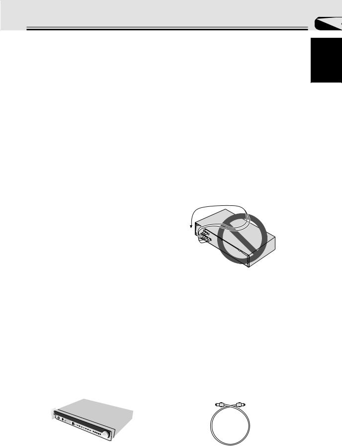
Storing optical cable
When storing optical cable, coil loosely as shown below. The cable may be damaged if bent around sharp corners.
more + than =
(15 cm)
01
English
9
En
Introductory Information
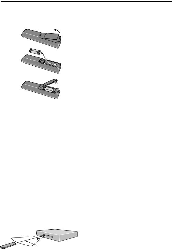
Loading the Batteries
The remote control operates on two AA batteries (supplied).
1
2
3
CAUTION:
Incorrect use of batteries may result in such hazards as leakage and bursting. Observe the following precautions:
•Never use new and old batteries together.
•Insert the plus and minus sides of the batteries properly according to the marks in the battery case.
•Batteries of the same shape may have different voltages. Do not use different batteries together.
•When disposing of used batteries, please comply with governmental regulations or environmental public institution’s rules that apply in your country or area.
Operating Range of the
Remote Control Unit
The remote control may not work properly if:
•There are obstacles between the remote control and the receiver's remote sensor.
•Direct sunlight or fluorescent light is shining onto the remote sensor.
•The receiver is located near a device that is emitting infrared rays.
•The receiver is operated simultaneously with another infrared remote control unit.
Maintenance of External
Surfaces
•Use a polishing cloth or dry cloth to wipe off dust and dirt. If the surfaces are very dirty, wipe with a soft cloth dipped in some neutral cleanser diluted five or six times with water and wrung out well, then wipe again with a dry cloth.
•Do not use furniture wax or cleaners. Never use thinners, benzine or insecticide sprays or other chemicals on or near this unit since they will corrode the surfaces.
•If you use a chemical-impregnated cleaning cloth, read the instructions carefully before use. These cloths may leave smear marks on half-mirror finish surfaces; if this happens, finish with a dry cloth.
•Unplug the unit when cleaning.
30 

30
7m
10
En
Connecting Your Equipment
Audio/Video Cords
Use audio/video cords (not supplied) to make analog audio and video connections.
Connect red plugs to R (right), white plugs to L (left), and the yellow plugs to VIDEO.
Be sure to insert completely.
R |
L |
|
VIDEO
Coaxial Cords/Optical Cables
Commercially available digital audio coaxial cords (standard video cords can also be used) or optical cables (not supplied) are used to connect digital components to this receiver.
Be sure to insert completely and in the case of the optical cable, right-side up. If it is inserted improperly it can break the shutter on the optical terminal (this won't, however, affect the connection or insertion of an optical cable).
Coaxial cord
(or standard composite Optical cable video cord)
02
English
11
En
Connecting Your Equipment
Before making or changing the connections, switch off the power and disconnect the power cord from the AC wall outlet.
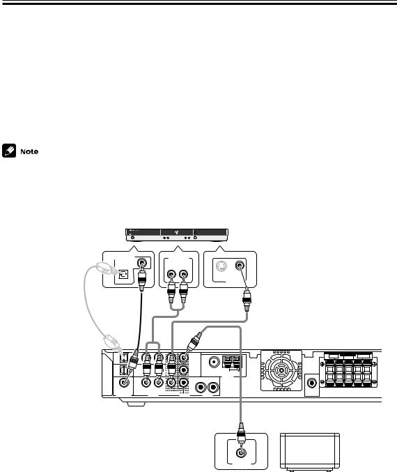
Connecting a DVD Player & TV
In order to play PCM/2Digital/DTS multichannel soundtracks, you need to make digital audio connections.
Connect your DVD player to this unit using either the coaxial digital terminal or the optical digital terminals, depending on which type of terminal your DVD has. The quality of these two types of connection is the same so it’s simply a matter of matching like with like. It is easiest, however, if you follow this receiver’s default settings and connect your DVD player to coaxial terminal. If your DVD player does not have an coaxial terminal, use the optical terminal to hook it up to this receiver. In this case you need to assign the DVD function to that terminal. See p.31 in order to do this. Follow the diagram below to hook up your DVD player to either the coaxial or optical terminal(s). Also, connect your TV to this receiver as shown below.
The basic default settings for the DIGITAL IN terminals are as follows: COAX: DVD; OPT. 1: TV/SAT; OPT. 2: DVR. If you need to use an optical terminal for your DVD use OPT.1. In this case, assign your coaxial terminal to TV/SAT (see p.31) and the optical default settings change to: OPT. 1: DVD; OPT. 2: DVR.
DVD Player (DV-550, etc.)
|
DIGITAL AUDIO OUT |
ANALOG OUT |
|
COAXIAL |
R L |
|
|
|
|
|
S |
|
OPTICAL |
VIDEO OUT |
Optical cable |
Coaxial |
Video cord |
(sold separately, |
cable (sold |
(sold separately) |
don’t pinch or |
separately) |
|
bend cable |
|
|
sharply) |
|
|
TV/ |
TV/ |
1 |
|
SAT |
SAT |
|
|
(DVD) |
IN |
|
|
OPT1 |
MONITOR |
|
|
|
|
||
DVR/ |
|
|
|
DVR/ |
OUT |
F M UNBAL75 Ω |
|
VCR |
VCR |
2 |
OPT2 |
IN |
AM LOOP |
|
ANTENNA |
|
|
|
DVD |
DVD |
|
|
R |
L |
(TV/ |
|
|
DVR/ |
|
|
SAT) |
IN |
|
|
|
|
|
|
|
VCR |
|
|
COA X |
R |
L |
|
SUB |
|
|
OUT |
||||
DIGITAL IN |
|
AUDIO |
VIDEO |
AUDIO |
WOOFER |
|
OUT |
R |
FRONT |
SPEAKERS |
SURROUND |
L |
|
L CENTER R |
|
Video cord (sold separately)
Why you need an analog connection as well as a digital one:
•If you don’t have an digital output on your DVD player you will need to use the analog connection shown here.
•If you want to get an audio signal from the VCR out you need an analog connection.
•If you want to use your DVD player for karaoke you need an analog connection.
MONITOR IN
TV
12
En
Connecting Your Equipment
Before making or changing the connections, switch off the power and disconnect the power cord from the AC wall outlet.
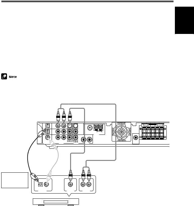
Connecting a Digital Tuner/Set Top Box
If you have an external digital tuner (like a set top box for satellite or cable TV) you need to connect it to either the optical digital terminals or the coaxial digital terminal in order to play digital cable/satellite broadcasting. The quality of these two types of connection is the same so it’s simply a matter of matching like with like. It is easiest, however, if you follow this receiver’s default settings and connect your cable/satellite tuner (or TV/SAT as it’s called on the remote control) to optical terminal 1. If your TV/SAT does not have an optical terminal, use the coaxial terminal to hook it up (consult the DVD hook up information on the previous page). In this case you need to assign the TV/SAT function to that terminal. See p.31 in order to do this. Follow the diagram below to hook up your TV/SAT to either the optical or coaxial terminal.
Make sure you use a digital connection as well as an analog one for the audio on the cable/satellite tuner, as pictured below.
The basic default settings for the DIGITAL IN terminals are as follows: COAX: DVD; OPT. 1: TV/SAT; OPT. 2: DVR. If you need to use the coaxial terminal for your TV/SAT, then assign the coaxial terminal to TV/SAT. The digital terminals settings change to: COAX: TV/SAT; OPT. 1: DVD; OPT. 2: DVR. (see p.31)
English
Optical cable (sold separately, don’t pinch or bend cable sharply)
TV/ |
|
TV/ |
|
SAT |
|
SAT |
|
(DVD) |
|
IN |
|
OPT1 |
|
|
|
|
|
|
|
DVR/ |
|
DVR/ |
|
VCR |
|
VCR |
|
OPT2 |
|
IN |
|
|
|
|
|
DVD |
|
DVD |
|
(TV/ |
|
|
|
SAT) |
|
IN |
|
|
COA X |
R |
L |
|
|
DIGITAL IN |
AUDIO |


 1
1
MONITOR |
|
OUT |
F M UNBAL75 Ω |
2 |
AM LOOP
ANTENNA
R |
L |
DVR/ |
|
VCR |
|
OUT |
|
VIDEO |
AUDIO |
R |
FRONT |
SPEAKERS |
SURROUND |
L |
|
L CENTER R |
|
SUB
WOOFER
OUT
Coaxial cable |
Video cord (sold separately) |
(sold separately) |
|
|
Audio cord |
|
(sold separately) |
Match the shape of terminal and the optical plug.
R L
DIGITAL OUT |
VIDEO OUT |
AUDIO OUT |
Why you need an analog connection as well as a
Digital Set Top Box
digital one:
•If you don’t have an digital output on your TV tuner you will need to use an analog connection.
•If the program you want to watch isn’t output from the digital terminals you need an analog connection.
•If you want to get a signal from a video deck instead of a TV tuner you need an analog connection.
13
En
Connecting Your Equipment
Before making or changing the connections, switch off the power and disconnect the power cord from the AC wall outlet.
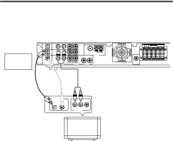
Connecting a TV with an Internal Digital Tuner
If you have an TV with an internal digital tuner follow the directions above for an external digital tuner and in addition hook up your TV, if you have not already done so when you hooked up your DVD player (see the previous page). Make sure you use a digital connection as well as an analog one for the audio, as pictured below.
Match the shape of terminal and the optical plug.
Optical cable (sold separately, don’t pinch or bend cable sharply)
TV/ |
TV/ |
1 |
|
SAT |
SAT |
|
|
(DVD) |
IN |
|
|
OPT1 |
MONITOR |
|
|
|
|
||
DVR/ |
|
|
|
DVR/ |
OUT |
F M UNBAL75 Ω |
|
VCR |
VCR |
2 |
|
OPT2 |
IN |
|
AM LOOP |
|
|
ANTENNA |
|
|
|
|
DVD |
DVD |
|
R |
L |
(TV/ |
|
DVR/ |
|
|
SAT) |
IN |
|
|
|
|
|
VCR |
|
|
COA X |
R |
L |
OUT |
|
|
|
|||
DIGITAL IN |
|
AUDIO |
VIDEO |
AUDIO |
Coaxial cable (sold
Audio cord
separately)
(sold separately)
R |
FRONT |
SPEAKERS |
SURROUND |
L |
|
L CENTER R |
|
SUB
WOOFER
OUT
DIGITAL OUT 
ANALOG OUT
TV with an
internal digital tuner
Connecting Video Components
Connect your video components to the terminals as shown below.
If you have a Digital Video Recorder (a DVR) you need to connect it digitally to either the optical digital terminals or the coaxial digital terminal in order to play and/or record multichannel sound. The quality of these two types of connection is the same so it’s simply a matter of matching like with like and using the available terminal(s) after you’ve hooked up your DVD player and cable/satellite/TV tuner.
Basically the easiest way to connect a DVR is to follow this receiver’s default settings and connect your cable/satellite tuner (or TV/SAT as it’s called on the remote control) and DVR to optical terminals 1 and 2 respectively, and connect the DVD to the coaxial terminal.
If this isn’t possible due to the types of terminals each component is equipped with, then you need to figure out which component will be used for the coaxial terminal and assign it properly (see p. 31). After that follow the optical terminal defaults (as below).
If you connected the coaxial terminal to DVD and thus left it on the default DVD setting the optical terminals default settings are:
OPT. 1: TV/SAT OPT. 2: DVR
If you assigned the coaxial terminal to TV/SAT the optical terminals default settings are: OPT. 1: DVD
OPT. 2: DVR
All video decks (both DVRs and VCRs) should be hooked up with analog connections as well. If you want to record programs it is necessary to connect to the DVR/VCR IN AUDIO terminals as shown next page.
14
En
Connecting Your Equipment
TV/ |
TV/ |
1 |
R |
FRONT |
SPEAKERS |
SURROUND |
L |
SAT |
SAT |
|
L CENTER R |
|
|||
(DVD) |
IN |
|
|
|
|
|
|
OPT1 |
MONITOR |
|
|
|
|
|
|
|
|
|
|
|
|
||
DVR/ |
DVR/ |
OUT |
F M UNBAL75 Ω |
|
|
|
|
VCR |
VCR |
2 |
|
|
|
|
OPT2 |
IN |
AM LOOP |
|
ANTENNA |
|
|
|
DVD |
DVD |
|
|
R |
L |
|
|
(TV/ |
|
|
DVR/ |
|
|
|
|
SAT) |
IN |
|
|
|
|
|
|
|
|
|
VCR |
|
|
|
|
COA X |
R |
L |
|
OUT |
SUB |
IN |
OUT |
DIGITAL IN |
|
AUDIO |
VIDEO |
AUDIO |
WOOFER |
CONTROL |
|
|
OUT |
|
|
||||
Optical cable (sold separately, don’t pinch or bend cable sharply)
OPTICAL COAXIAL
DIGITAL OUT
Audio/video cord (sold separately)
VIDEO


 L
L
AUDIO
R
OUTPUT INPUT 2 /AUTO REC
DVD RECORDER DVR-7000
SMART JOG
|
|
|
DVD |
|
|
|
FL OFF |
2DIGITAL |
Î |
TIMER |
AUTO REC |
|
|
STANDBY/ON |
|
|
|
|
|
|
FL DIMMER |
|
|
OPEN/CLOSE |
|
|
|
|
DISCNAVI |
|
0 |
FUNCTION |
|
|
OPEN |
|
|
|
|
|
|
|
|
|
7 STOP |
3 PLAY |
8PAUSE |
REC |
DVD Recorder (DVR-7000, etc.)
Audio/video cord (sold separately)
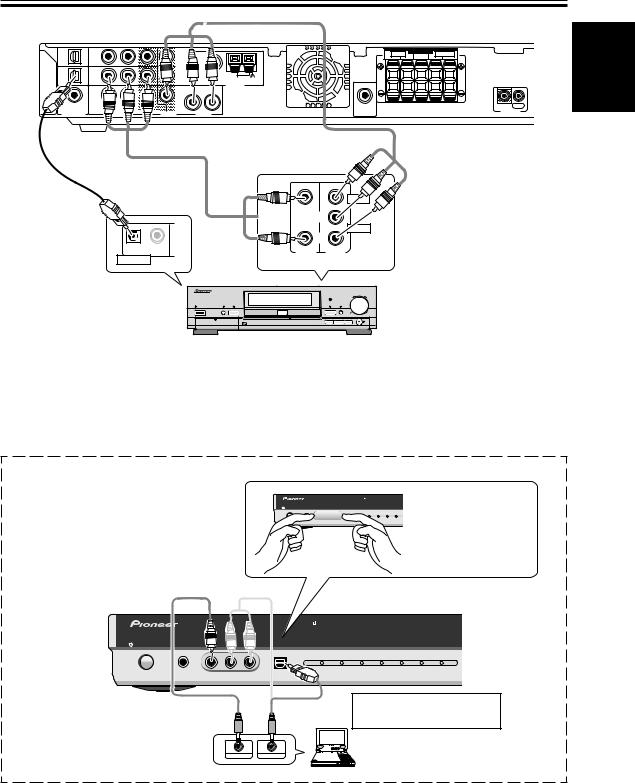
You can only record audio signals from video components hooked up with analog connections.
If the input component and the receiver are only connected with an digital cable (coaxial or optical), which is for audio, you need to connect analog video and audio cables in order to be able to record video programs with soundtracks.
Front
First, take the cover off the inputs.
Select the component hooked up to the Front video connections with the FRONT button on the remote control or front panel.
STANDBY/ON |
PHONES |
FRONT INPUT |
|
|
|
|
|
|
|
INPUT SIGNAL |
|
SURROUND |
|
|
|
|
2 |
DTS |
AUTO |
PHONES/ |
|
|
|
DIGITAL |
|
|
VIRTUAL P |
|
VIDEO |
L AUDIO R |
DIGITAL IN |
|
|
|
Place your fingers on either side of the cover and remove it by pulling gently.
English
STANDBY/ON |
PHONES |
FRONT INPUT |
|
|
|
|
|
|
|
|
|
INPUT SIGNAL |
|
SURROUND MODE |
|
||
|
|
|
2 |
DTS |
AUTO |
PHONES/ |
2 |
ADVANCED SOUND |
|
|
|
DIGITAL |
|
|
VIRTUAL |
PRO LOGIC |
MODE |
|
VIDEO |
L AUDIO R |
DIGITAL IN |
|
|
|
|
|
Match the shape of terminal and the optical plug.
VIDEO IN/OUT |
AUDIO IN/OUT |
Portable DVD Player (etc.) |
15
En
Connecting Your Equipment
Before making or changing the connections, switch off the power and disconnect the power cord from the AC wall outlet.
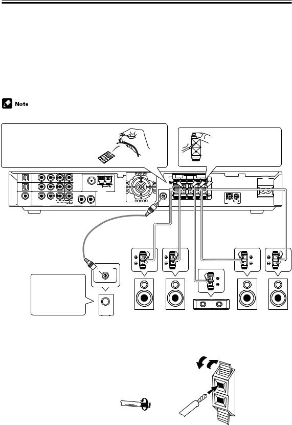
Connecting Speakers
A full complement of five speakers is shown here but, naturally, everyone’s home setup will vary. Simply connect the speakers you have in the manner described below. The receiver will sense which speakers you have hooked up. The receiver will work with just two stereo speakers (called “Front” speakers in the diagram) but we recommend you use five speakers. If you don’t hook up surround speakers you need to adjust the Listening mode settings (see p. 33).
Make sure you connect the speaker on the right to the right terminal and the speaker on the left to the left terminal. Also make sure the positive and negative (+/–) terminals on the receiver match those on the speakers.
• Use speakers with a nominal impedance of 6 Ω to 16 Ω.
Before hooking up your speakers affix the color-coded stickers with the appropriate names (for example, “FRONT R”) to the speaker wire so you always know which speaker each wire is connected to.
TV/ |
TV/ |
|
1 |
|
SAT |
SAT |
|
|
|
(DVD) |
IN |
|
|
|
OPT1 |
|
MONITOR |
|
|
|
|
|
||
DVR/ |
DVR/ |
|
OUT |
F M UNBAL75 Ω |
VCR |
VCR |
|
2 |
|
OPT2 |
IN |
|
|
AM LOOP |
|
|
|
ANTENNA |
|
|
|
|
|
|
DVD |
DVD |
|
R |
L |
(TV/ |
|
DVR/ |
|
|
SAT) |
IN |
|
|
|
|
|
VCR |
|
|
COA X |
R |
L |
OUT |
|
|
|
|||
DIGITAL IN |
|
AUDIO |
VIDEO |
AUDIO |
Audio cord (sold separately)
SUB
WOOFER
OUT
While pressing down the speaker tab push the speaker wire into the terminal and release speaker terminal tab.
|
FRONT |
SPEAKERS |
SURROUND |
|
AC IN |
R |
|
L CENTER R |
|
L |
IN OUT
CONTROL
Speaker wire (sold separately)
 LINE LEVEL
When you’re hooking up your subwoofer make sure its power cord is disconnected.
Powered |
Front R |
Front L |
Center |
Surround R |
Surround L |
Subwoofer (SW) |
(R) |
(L) |
(C) |
(RS) |
(LS) |
Speaker terminals
Use good quality speaker wire to connect the speakers to the receiver.
1Twist about 10 mm of bare wire strands together.
2Push in the speaker terminal tab and insert the wire.
3Release speaker terminal tab, it should snugly grip the speaker wire.
10 mm
Caution:
ª ·
16 |
Make sure that all the bare speaker wire is twisted together and inserted fully into the speaker terminal. If any of the |
bare speaker wire touches the back panel it may cause the power to cut off as a safety measure. |
En
Connecting Your Equipment
Hints on Speaker Placement
Speakers are usually designed with a particular placement in mind. Some are designed to be floor standing, while others should be placed on stands to sound their best. Some should be placed near a wall; others should be placed away from walls. Follow the guidelines on placement that the speaker manufacturer provided with your particular speakers to get the most out of them.
•Place the front left and right speakers at equal distances from the TV.
•When placing speakers near the TV, we recommend using magnetically shielded speakers to prevent possible interference, such as discoloration of the picture when the TV is switched on. If you do not have magnetically shielded speakers and notice discoloration of the TV picture, move the speakers farther away from the TV.
•Install the center speaker above or below the TV so that the sound of the center channel is localized at the TV screen.
CAUTION!
If you choose to install the center speaker on top of the TV, be sure to secure it by suitable means to reduce the risk of damage or injury resulting from the speaker falling from the TV in the event of external shocks such as earthquakes.
•If possible, install the surround speakers slightly above ear level.
•Try not to install the surround speakers farther away from the listening position than the front and center speakers. Doing so can weaken the surround sound effect.
•Install the subwoofer on the same plane as the front speakers.
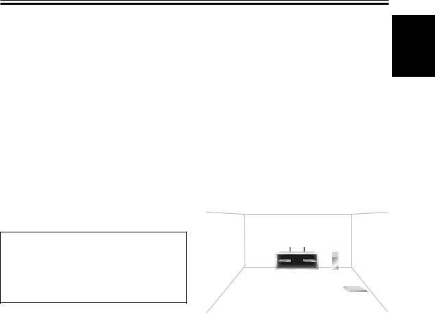
To achieve the best possible surround sound, install your speakers as shown on the right. Be sure all speakers are installed securely to prevent accidents and improve sound quality.
Overhead view of speaker set up
|
|
Front |
Front Left (L) |
Center (C) |
Right (R) |
Subwoofer (SW)
Surround |
Surround |
Left (LS) |
Right (RS) |
|
Listening Position |
3-D view of speaker set up
English
17
En
Connecting Your Equipment
Before making or changing the connections, switch off the power and disconnect the power cord from the AC wall outlet.
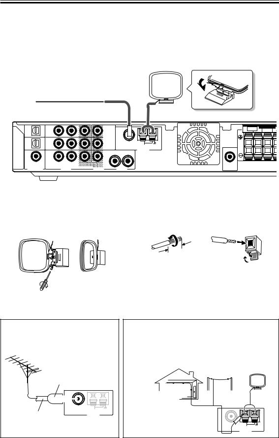
Connecting Antennas
Connect the AM loop antenna and the FM wire antenna as shown below. To improve reception and sound quality, connect external antennas (see Using External Antennas, below).
TV/ |
TV/ |
|
1 |
|
SAT |
SAT |
|
|
|
(DVD) |
IN |
|
|
|
OPT1 |
|
MONITOR |
|
|
|
|
|
||
DVR/ |
|
|
|
|
DVR/ |
|
OUT |
F M UNBAL75 Ω |
|
VCR |
VCR |
|
2 |
|
OPT2 |
IN |
|
|
AM LOOP |
|
|
|
ANTENNA |
|
DVD |
|
|
|
|
DVD |
|
R |
L |
|
(TV/ |
|
DVR/ |
|
|
SAT) |
IN |
|
|
|
|
|
VCR |
|
|
COA X |
|
|
|
|
R |
L |
OUT |
|
|
|
|
|||
DIGITAL IN |
|
AUDIO |
VIDEO |
AUDIO |
|
FRONT |
SPEAKERS |
R |
L CENTER R |
SUB
WOOFER
OUT
AM loop antenna
Assemble the antenna and connect to the receiver. Attach to a wall, etc. (if desired) and face in the direction that gives the best reception.
AM Antenna connectors
Twist the exposed wire strands together push the tab back, insert into the hole and release connector.
10mm
Using External Antennas
To improve FM reception
Connect an external FM antenna.
PAL connector
|
|
|
|
|
|
|
|
|
|
|
|
|
|
|
|
|
|
|
|
|
|
|
|
|
|
|
|
F M UNBAL75 Ω |
|||||||||||
|
|
|
|
|
|
|
|
|
|
|
|
AM LOOP |
|||||||
75 Ω coaxial cable |
|
|
|
|
ANTENNA |
||||||||||||||
|
|
|
|
|
|
|
|
|
|
|
|
|
|
|
|||||
18
En
FM wire antenna
Connect the FM wire antenna and fully extend vertically along a window frame or other suitable area.
To improve AM reception
Connect a 5-6 m length of vinyl-coated wire to the AM antenna terminal without disconnecting the supplied AM loop antenna.
For the best possible reception, suspend horizontally outdoors.
Outdoor antenna
Indoor antenna (Vinyl-coated wire)
5–6m
FM UNBAL75 Ω
AM LOOP
ANTENNA
Connecting Your Equipment
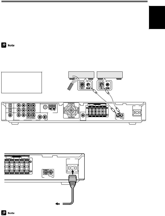
Operating other Pioneer Components with this Unit’s Sensor
By connecting a control cord to the CONTROL terminals of the respective equipment, you can control several Pioneer components using one remote sensor. Following the diagram below you will see that one component feeds the CONTROL OUT terminal and on the other end another component is connected to the CONTROL IN terminal. The component that is the end point (the one that has a cord hooked up to its CONTROL OUT only) it is the component whose sensor you will use. Point the remote control at that sensor when you want to operate the any of the equipment connected by this system. In the example below you would point the remote control unit towards the remote sensor of the equipment on the left.
•You can also control Pioneer components by pointing the receiver's remote control directly at the component. This type of operation does not require control cords. See page 47 for more information.
•To use this kind of remote control you have to hook up a control cord AND the have the component and receiver hooked up with analog RCA audio/video cords as well (see pages 12–15).
Point remote control towards remote sensor of component that only has a cord connected to its CONTROL OUT terminal
Components with an CONTROL terminals
Mono mini plug (optional)
Components with an CONTROL terminals
Mono mini plug (optional)
TV/ |
TV/ |
|
|
|
|
FRONT |
SPEAKERS |
SURROUND |
|
|
SAT |
SAT |
|
1 |
|
R |
|
L CENTER R |
|
L |
AC IN |
(DVD) |
|
|
|
|
||||||
OPT1 |
IN |
|
MONITOR |
|
|
|
|
|
|
|
DVR/ |
|
|
|
|
|
|
|
|
|
|
DVR/ |
|
OUT |
F M UNBAL75 Ω |
|
|
|
|
|
|
|
VCR |
VCR |
|
2 |
AM LOOP |
|
|
|
|
|
|
OPT2 |
IN |
|
|
|
|
|
|
|
|
|
|
|
|
|
ANTENNA |
|
|
|
|
|
|
DVD |
|
|
R |
L |
|
|
|
|
|
|
DVD |
|
|
|
|
|
|
|
|||
(TV/ |
|
DVR/ |
|
|
|
|
|
|
|
|
SAT) |
IN |
|
|
|
|
|
|
|
|
|
|
|
VCR |
|
|
|
|
|
|
|
|
COA X |
|
|
|
SUB |
|
|
|
IN |
OUT |
|
R |
L |
OUT |
|
|
|
|
||||
DIGITAL IN |
|
AUDIO |
VIDEO |
AUDIO |
WOOFER |
|
|
|
CONTROL |
|
|
OUT |
|
|
|
|
|
||||
English
Plugging in the Receiver
After you have connected all your components, including the speakers, plug the receiver into a wall outlet.
|
FRONT |
SPEAKERS |
SURROUND |
|
AC IN |
R |
|
L CENTER R |
|
L |
IN OUT
CONTROL
to wall outlet
• The power cord is removable from main unit for storage.
Power cord CAUTION!
Handle the power cord by the plug. Do not pull out the plug by tugging the cord and never touch the power cord when your hands are wet as this could cause a short circuit or electric shock. Do not place the unit or a piece of furniture, etc., on the power cord, or pinch the cord. Never make a knot in the cord or tie it with other cords. The power cords should be routed such that they are not likely to be stepped on. A damaged power cord can cause a fire or give you an electrical shock. Check the power cord once in a while. When you find it damaged, ask your nearest PIONEER authorized service center or your dealer for a replacement.
19
En
03 Displays & Controls
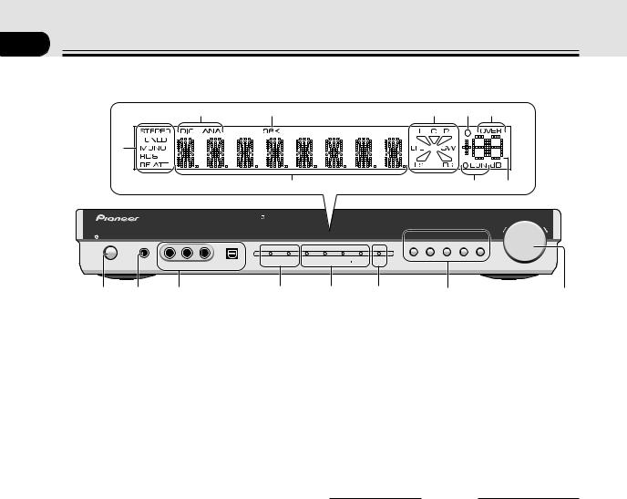
Front Panel
|
|
0 |
- |
|
|
|
= |
~ |
! |
|
9 |
|
|
|
|
|
|
|
|
|
|
|
|
|
|
$ |
|
|
|
@ |
# |
|
|
|
|
|
|
|
|
|
MASTER VOLUME |
|
|
STANDBY/ON |
PHONES |
FRONT INPUT |
|
|
|
|
DVD TV/SAT |
DVR/VCR FM/AM FRONT |
DOWN |
UP |
|
|
|
INPUT SIGNAL |
SURROUND MODE |
|
|
|
|
||
|
|
|
2 |
DTS AUTO |
PHONES/ |
2 ADVANCED |
SOUND |
|
|
|
|
|
|
DIGITAL |
|
VIRTUAL |
PRO LOGIC |
MODE |
|
|
|
|
VIDEO |
L AUDIO R |
DIGITAL IN |
|
|
|
|
|
|
|
1 |
2 |
3 |
|
4 |
5 |
6 |
7 |
|
8 |
|
1  STANDBY/ON (Main power) button
Pressing this button switches the receiver ON from STANDBY mode.
RECEIVER  button on the remote control also toggles between ON and STANDBY mode.
The receiver uses a small amount of electricity (less than 1W) in STANDBY mode.
2 PHONES jack
Use to connect headphones (this switches the speakers off).
3FRONT INPUT
You can connect a portable DVD player, video camera, video game system, or whatever equipment you would like to have handy, to the FRONT INPUT
(refer to page 15).
4INPUT SIGNAL indicators
Indicates the kind of input signal. 2DIGITAL:
When a 2DIGITAL source is input this indicator
will light. DTS:
When a DTS source is input this indicator will light.
5SURROUND MODE indicators
Indicates the SURROUND mode of input signal. AUTO:
Lights when the AUTO mode is selected. This mode automatically selects which kind of signal is being input and plays back in the appropriate mode. PHONES/VIRTUAL:
Lights when the VIRTUAL or PHONES SURROUND mode is selected. The VIRTUAL mode simulates surround sound for two speakers (when headphones are not plugged in, see p.33). The PHONES SURROUND mode simulates surround sound for headphones, when they are plugged in.
2PRO LOGIC II:
Lights when the 2PRO LOGIC II mode is selected. This mode automatically plays back in 2PRO LOGIC II (see p.33).
20
ADVANCED:
Lights when an ADVANCED mode is selected. These modes playback emphasizing certain characteristics of the sound (see p.33–34).
6SOUND MODE
Lights when you have chosen one of the sound modes to be applied to playback (see p.35).
7Input buttons
Use to select the playback source: the possibilities are
DVD, TV/SAT, DVR/VCR, FM/AM and FRONT.
8MASTER VOLUME
Use to set the overall listening volume.
DISPLAY
9TUNER indicators
STEREO: Lights when a stereo FM broadcast is being received in auto stereo mode.
TUNED: Lights when a broadcast is being received. MONO: Lights when the mono mode is set using MPX (on the remote control).
RDS: Lights when an RDS broadcast is received. RF ATT: Lights when the RF ATT is on (see p.36).
0Digital (DIG) & Analog (ANA) indicators
Light according to the kind of signal, digital or analog, received (see p.44).
-96kHz playback indicator
Lights when a 96 kHz source is being played.
=Format indicator
Shows which speakers are currently in use based on
the listening mode chosen, the source material and the type of decoding being used (see p.24).
~ SLEEP indicator
Lights when the SLEEP function is set or active (see p.44).
!OVER indicator
Lights when the analog signal is too powerful, causing possible distortion (see p.31).
En
|
Displays & Controls |
|
|
@ EON indicators |
# Volume level indicator |
EON lights when it has been set. The dot indicator |
$ Character display |
next to it lights when the station you are currently |
Shows the current input (DVD, TV/SAT, etc.), |
tuned to carries the EON data service. |
listening mode, radio frequency, etc. |
Rear Panel
1TV/SAT IN terminals (connect a TV/SAT set top box here, see page 13)
Use these terminals to input a TV/SAT signal (or from another kind of source, if you choose). Make sure to connect to the video terminals and both the analog and optical digital terminals for audio. To be able to play digital surround soundtracks you need to make digital connections. To do this it’s best to use the optical digital terminal here but you can use the coaxial digital terminal if necessary (in this case you
need to assign the terminal to the TV/SAT function. See page 31 in order to do this).
2MONITOR OUT terminals (connect a TV or monitor here, see pages 12,14)
Use these terminals to output the signal from the
above terminals 1, 5 or 6 and FRONT INPUT. These are video jacks. MONITOR 2 outputs the same signal as MONITOR 1.
3 ANTENNA terminals
Connect AM or FM antennas here (see page 18).
4SPEAKERS terminals
Use these terminals to connect speakers to the receiver (see page 16).
5DVR/VCR IN/OUT terminals (connect a DVR or VCR here, see page 14–15)
Use the optical digital terminal to connect a DVR out
digitally to this receiver. There are also analog terminals to input and output the audio and video signal from a DVR, VCR (or a video camera, etc.).
6DVD IN terminals (connect a DVD player here, see page 12)
Use these terminals to input the signal from a DVD player. Make sure to connect to the video terminals and both the analog and coaxial digital terminals for audio. To be able to play Dolby Digital and other surround soundtracks you need to make digital connections. To do this it’s best to use the coaxial digital terminal but you can use the OPT 1 digital
terminal if necessary (in this case you need to assign the coaxial digital terminal to the TV/SAT function. See page 31 in order to do this).
7 SUBWOOFER OUT terminals
Use this terminal to connect a powered subwoofer to the receiver (see page 16).
8CONTROL IN/OUT terminal
You can use this jack to hook up other PIONEER equipment, that bears the CONTROL terminal, so
that you can control them all with the remote control for this receiver (see page 19).
9AC IN (Power In)
Hook up the power cord to this terminal.
English
21
En
Displays & Controls
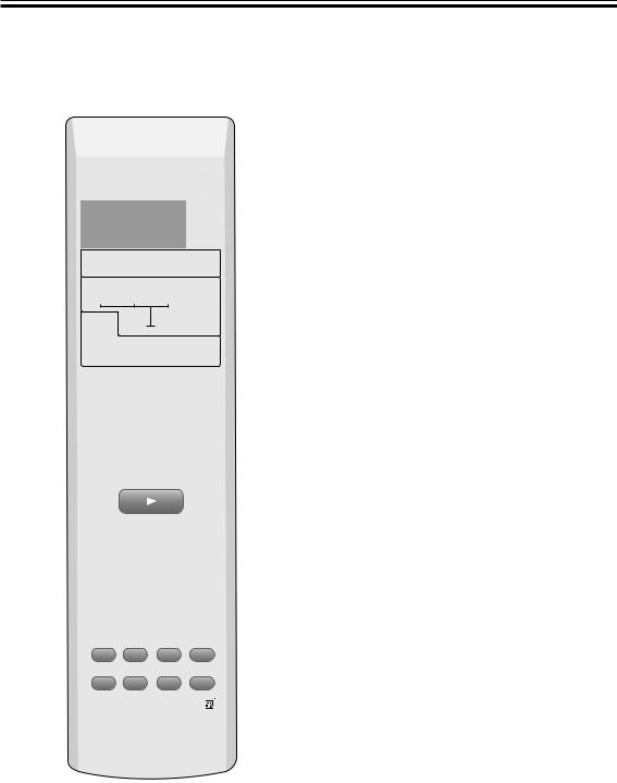
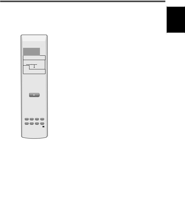
Remote Control
All the buttons on the remote control are explained here. See pages 49 & 50 for details relating to using the remote control with other components (like your DVD player or TV/SAT tuner).
1
2
3
4
5
6
7
8
9
0
RECEIVER |
|
|
SOURCE |
SIGNAL SELECT |
|
|
|
|
|
|
SLEEP |
DVD |
TV/SAT |
FRONT |
|
|
|
|
DIMMER |
DVR/ VCR |
FM / AM |
|
|
AUTO |
SURROUND ADVANCED |
SOUND |
|
MODE |
|||
SETUP |
TEST TONE |
CH_SELECT |
ROOM |
SETUP |
|||
|
|
|
ENTER |
MUTE |
|
|
|
|
MASTER |
|
|
|
VOLUME |
|
|
TOP MENU |
DISPLAY |
T.EDIT MENU |
|
P |
TUNE |
MENU |
|
|
|
||
ST |
|
ST |
|
|
ENTER |
|
|
AUDIO |
TUNE |
SUBTITLE |
|
|
|
||
EON |
RF ATT |
||
P |
|
|
GUIDE |
EXIT |
|
|
A |
SEARCH |
CLASS |
MPX |
D.ACCESS |
B |
C |
D |
E |
ENTER
10
TV CONTROL
INPUT
CHANNEL SELECT CHANNEL VOLUME
RECEIVER
1RECEIVER  (Power) button:
This switches between STANDBY mode and power
-ON for this receiver.
2SIGNAL SELECT button (See p.44):
=Press SIGNAL SELECT repeatedly to select one of the following:
~ANALOG: To select an analog signal. DIGITAL: To select a digital signal.
!AUTO: This is the default. If there are analog and digital signals input, the receiver automatically
selects digital. If only analog is input the receiver will select analog.
3Input/Control Mode Select buttons:
Use to put the receiver/remote control in the input mode stated on the button. The FM/AM button puts the receiver in tuner mode if it was in another mode and switches between the FM and the AM band if
@the receiver was already in tuner mode.
4Listening Mode buttons: AUTO button:
#Use this button for direct decoding of the input signal with no added sound effects. The receiver will
$automatically detect what kind of signal (stereo, multichannel, etc.) is being input and play accordingly.
SURROUND button (see page 34):
 % Use this button to choose one of the surround listening modes this receiver is equipped with.
ADVANCED button (see page 34):
^Use this button to choose one of the advanced listening modes this receiver is equipped with.
SOUND MODE button (see page 35):
Use this button to choose one of the sound modes this receiver is equipped with.
5System setup buttons:
&SETUP button (see page 27):
Use this button to start the receiver setup process which adjusts the settings to your particular system.
TEST TONE button (see page 32):
Use to sound the TEST TONE when setting the volume level of each channel.
CH SELECT button (see page 32, note):
Use to select a speaker when setting the volume level of each channel.
ROOM SETUP button (see page 26):
Use to set the distance from your speakers to your normal listening position.
+/– buttons (see pages 28–32):
Use these buttons when making adjustments to the SETUP, TEST TONE, or CH.SELECT features.
22
En

Displays & Controls
ENTER button:
Use this button to enter Room Setup commands. You can also use this button to exit a SETUP mode.
6Volume buttons:
MASTER VOLUME +/– buttons:
Use to set the overall listening volume.
MUTE button (see page 43):
Use to mute the sound or restore the sound if it
has been muted.
7TOP MENU button:
Use to return to the most basic menu on a DVD player or disc. Also used for some tuner commands.
8AUDIO button:
Use to switch the audio tracks of a DVD when in DVD mode or to access the EON function when in tuner mode.
9Number buttons:
Use to enter track number on discs or radio
frequencies.
0CHANNEL +/– buttons:
Use to select channels on other components such
as a DVR or satellite tuner.
-LED indicator:
This indicator flashes when a command is sent from the remote control to the receiver. It also flashes at when teaching the receiver preset codes.
=SOURCE  (Power) button:
Use this button to turn on and off the power of
other components.
~ SLEEP button (see page 44):
Use to put the receiver in sleep mode and select the amount of time before the receiver turns off.
!DIMMER button (see page 43):
Press to change the display brightness. The DIMMER button allows you to cycle through the
four different brightness strengths for the display.
@ MENU button:
Use to return to the most basic menu on a DVD player or disc. Also used for some tuner commands.
#} ] ’ ‘ & ENTER buttons
Use these arrow buttons when adjusting the tuner
or navigating TV or DVD menus. See these respective sections for more information.
$SUBTITLE button:
Use to switch the subtitles on a DVD player or disc. Also used to turn on RF ATT when in tuner mode.
%Component/Tuner/Satellite Tuner/CATV control buttons:
The main function of these buttons (3, 7, etc.) is to control a component (CD, for example) after you have selected it using the Input/Control Mode Select buttons. The tuner/satellite tuner controls above these buttons can be accessed after you have selected the corresponding Input/ Control Mode Select buttons (TUNER or SAT, etc.). In this case the buttons marked with letters (A, etc.) or EXIT will access preset channels or functions, depending on your particular satellite/ cable TV system.
SEARCH button:
Use when searching for stations in RDS mode.
CLASS button (page 37–38):
Switches between the three banks (classes) of radio station presets.
MPX button (page 36):
Switches between stereo and mono reception of FM broadcasts. If the signal is weak then switching to mono will improve the sound quality. Also acts as a stop button for CDs, tapes,
or DVDs.
D. ACCESS button (page 37):
After pressing, you can access a radio station directly using the number buttons.
^ ENTER button (page 49–50):
It can be used to enter commands for TV, CATV and TUNER.
&TV CONTROL buttons:
These controls are for your TV. They are dedicated TV controls and will work no matter what mode the remote control is in. They can, however, be set for different TVs. By default they will control the TV. Thus if you only have one TV, assign it to the TV/SAT button (see page 47).
English
23
En
04 Basic Playback
Checking the Settings on Your DVD (or other) Player
If you don’t set the following two features correctly you may experience problems with your surround sound (for example: no sound whatsoever; the sound is unidimensional or lacks punch; or other problems).
1 Digital output from your DVD player or other component outputting a digital source
Set the DVD player so the signals below are output from the optical terminal (if you are unsure how to do this check the manual that came with your DVD player). It may or may not be necessary to set the digital output on other components, like a satellite tuner. Check the manual that came with the component.
•Dolby Digital
•DTS
•96 kHz PCM (2 channel stereo)
2Checking the soundtrack on your disc
Choose the surround sound signal (for example, Dolby Digital 5.1 ch or Dolby Surround) that you want to hear from the disc. Check the manual that came with your DVD player for more information.
•Depending on your DVD player or source discs you may not be able to output sound from other than digital 2 channel stereo and analog. In this case you need to change the listening mode to SURROUND if you want multichannel surround sound.
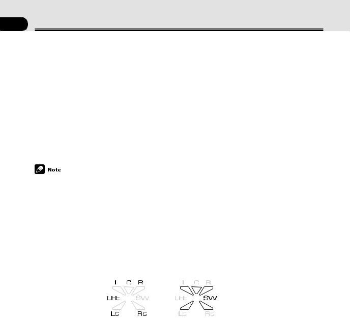
Program Format/Speaker Channel Indicators
One very useful feature of this receiver is the Program Format/Speaker Channel Indicators. This indicator looks something like this:
The letters |
The triangular segments and SW |
(Input indicator) |
(Output indicator) |
With this indicator you can determine which channels are present in a Dolby Digital or DTS source as well as the speakers that are currently being used. The letters L, C, R, LFE, LS & RS represent the signal being input for each channel respectively, with LFE being the Low Frequency Effects channel which feeds your subwoofer. These letters will only appear if the input is a Dolby Digital or DTS signal.
The triangular segments and SW represent the output from the receiver. The upper segments represent the front left, center, and front right speakers while the bottom segments represent the surround left and surround right channels. SW represents the subwoofer channel. If you have all of these speakers connected and are using either a multichannel signal (for example, Dolby Digital 5.1 ch or Dolby Surround), or a listening mode to get five channels sound, all five of the segments will light. For stereo signals only the front left, center, and front right speakers segments will light.
In some cases, depending on the source and listening mode, the output channels may not light up.
24
En
Basic Playback
Playing a Source
Here are the basic instructions for playing a disc or videotape (or any other source) with your home theater system. The following pages will tell you about refinements you can make to the sound but the below procedure (with the settings you have already made) should allow you to get enjoyable home theater.
2
3
RECEIVER |
SOURCE |
SIGNAL SELECT |
SLEEP
DVD |
TV/SAT |
FRONT |
|
|
|
|
DIMMER |
DVR/ VCR |
FM / AM |
|
|
AUTO |
SURROUND ADVANCED |
SOUND |
|
MODE |
|||
SETUP |
TEST TONE |
CH_SELECT |
ROOM |
SETUP |
|||
|
|
|
ENTER |
MUTE |
|
|
|
|
MASTER |
|
|
|
VOLUME |
|
|
TOP MENU |
DISPLAY |
T.EDIT MENU |
|
P |
TUNE |
MENU |
|
|
|
||
4
7
1Turn on the power of the playback component (for example a DVD player), your TV and subwoofer (if you have one).
2Press RECEIVER  to turn the power on.
3Select the source (like a DVD player) you want to playback using the individual Input buttons on the remote control.
4Set the signal select to AUTO (if necessary).
ST |
ENTER |
ST |
|
|
|
||
AUDIO |
TUNE |
|
SUBTITLE |
|
|
|
|
EON |
|
|
RF ATT |
P |
|
|
GUIDE |
EXIT |
|
|
A |
SEARCH |
CLASS |
MPX |
D.ACCESS |
E |
C |
D |
E |
ENTER
10
TV CONTROL
INPUT
CHANNEL SELECT CHANNEL VOLUME
RECEIVER
2  STANDBY/ON button
STANDBY/ON |
PHONES |
FRONT INPUT |
|
|
|
|
|
|
|
INPUT SIGNAL |
|
|
|
|
|
|
2 |
DTS |
AUTO |
P |
|
|
|
DIGITAL |
|
|
V |
|
VIDEO |
L AUDIO R |
DIGITAL IN |
|
|
|
3 Input buttons |
7 MASTER VOLUME |
|||
|
|
|
MASTER VOLUME |
|
|
|
DVD TV/SAT |
DVR/VCR FM/AM FRONT DOWN |
UP |
SURROUND MODE |
|
|
|
|
TO PHONES/ |
2 |
ADVANCED SOUND |
|
|
VIRTUAL |
PRO LOGIC |
MODE |
|
|
5Make sure the TV is set to this receiver.
If you’re not sure which input on your TV this receiver is hooked up to confirm the input jack on the back of the TV and consult the manual that came with your TV to figure out the proper setting.
6Start playback of the component you selected in step 3.
7Press MASTER VOLUME (+/–) to adjust the volume level.
•If you want to use analog sources choose analog with the SIGNAL SELECT button (see page 44).
•When you’re using your TV’s internal tuner the TV shouldn’t be set to this receiver (step 5 above).
•For Karaoke make sure the equipment is hooked up with analog connections and choose analog with the SIGNAL SELECT button (see page 44).
English
25
En
05 Fine Tuning Your Surround Sound
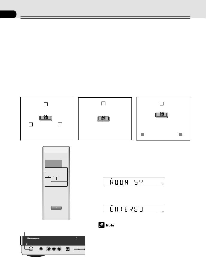
Room Setup
This setup establishes the distances from your speakers to your normal listening position. It is important for the receiver to know these distances so it can output proper surround sound. Alternatively, you can make more precise speaker distance settings on page 27-29. You don’t have to do both, however.
There are three choices for speaker distances here. They are marked ‘S’, ‘M’ and ‘L’ but they represent the relationship between how far your front speakers and your surround speakers are from your normal listening position, i.e. the relationship in distance between the speakers and your listening position. ‘S’ should be used when your surround speakers are nearer your main listening position than your front speakers. ‘M’ should be used when all your speakers are equidistant from your main listening position. ‘L’ should be used when your surround speakers are farther from your main listening position than your front speakers.
Follow the instructions below to set the room type.
S (surround speakers closer to |
M (speakers are equidistant to |
listening position) |
listening position) |
L (front speakers are closer to listening position)
L |
|
|
C |
|
|
R SW |
|
L |
|
C |
R SW |
L |
|
C |
R SW |
|||||||||
|
|
|
|
|
|
|
|
|
|
|
|
|
|
|
|
|
|
|
|
|
|
|
|
|
|
|
|
|
|
|
|
|
|
|
|
|
|
|
|
|
|
|
|
|
|
|
|
|
|
|
|
|
|
|
|
|
|
|
|
|
|
|
|
|
|
|
|
|
|
|
|
|
|
|
|
|
|
|
|
|
|
|
|
|
|
|
|
|
|
|
|
|
|
|
|
|
|
|
|
|
|
|
|
|
|
|
|
|
|
|
|
|
|
|
|
|
|
|
|
|
|
|
|
|
LS |
RS |
|
||
|
|
|
|
|
LS |
RS |
LS |
RS |
1 |
RECEIVER |
|
|
SOURCE |
|
SIGNAL SELECT |
|
|
|||
|
|
|
SLEEP |
|
|
|
DVD |
TV/SAT |
FRONT |
|
|
|
|
|
|
DIMMER |
|
|
DVR/ VCR |
FM / AM |
|
|
|
|
AUTO |
SURROUND ADVANCED |
SOUND |
|
|
|
MODE |
2 |
|||
|
SETUP |
TEST TONE |
CH_SELECT |
ROOM |
|
|
SETUP |
|
|||
|
|
|
|
ENTER |
3 |
|
MUTE |
|
|
|
|
|
|
MASTER |
|
||
|
|
VOLUME |
|
||
|
TOP MENU |
DISPLAY |
T.EDIT MENU |
|
|
|
P |
TUNE |
MENU |
|
|
|
|
|
|
||
|
ST |
|
ST |
|
|
|
|
ENTER |
|
|
|
|
AUDIO |
TUNE |
SUBTITLE |
|
|
|
|
|
|
||
|
EON |
RF ATT |
|
||
|
P |
|
|
GUIDE |
|
|
EXIT |
|
|
A |
|
|
SEARCH |
CLASS |
MPX |
D.ACCESS |
|
|
E |
C |
D |
E |
|
ENTER
1  STANDBY/ON button
STANDBY/ON |
PHONES |
FRONT INPUT |
|
|
|
|
|
INPUT SIGNAL |
|
|
|
|
2 |
DTS |
|
|
|
DIGITAL |
|
|
VIDEO |
L AUDIO R |
DIGITAL IN |
|
26
1Press RECEIVER  to turn the power on.
2Press ROOM SETUP.
Cycle through the ‘S’, ‘M’, or ‘L’ settings using the ROOM SETUP button and choose the one that best represents the placement of your speakers around the room.
The setting will blink for five seconds.
3While the display is blinking press ENTER.
The setting is input into the system and the display shows ENTERED.
•These speaker settings will automatically adjust the distance between your listening position and the speakers as well as the output level from each speaker. It is also possible to select these functions manually. To do so see below. For the distance between the listening position and the speakers see pages 27-29; For the output level of each speaker see page 32.
•The settings made most recently, whether here or manually, on the pages mentioned directly above, will supercede any previous settings.
•The default setting is ‘M’.
En
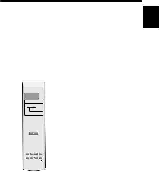
Fine Tuning Your Surround Sound
Personalizing Your Surround
Sound
This receiver will make the necessary speakers settings automatically so you can use it to get enjoyable surround sound without doing anything, but making more exact settings here will give you finer surround sound.
For better surround sound complete the instructions that follow the speaker settings. Use the first two steps on this page and continue on page 28. In this way you can get maximum performance out of the receiver.
For best results, start with Front speakers setting mode and make your initial adjustments in the order described below.
The current settings are displayed automatically.
•Front speakers setting mode (page 28)
Use to specify the size and configuration of the FRONT speakers you have connected.
•Center speaker setting mode (page 28)
Use to specify the size and configuration of the CENTER speaker you have connected.
•Surround speaker setting mode (page 28)
Use to specify the size and configuration of the SURROUND speakers you have connected.
•Subwoofer setting mode (page 28)
You only need to do these settings once (unless you change the placement of your current speaker system or add new speakers, etc.). The following pages offer a more detailed description of the settings available for each mode. The default setting is also shown on each page.
1 |
RECEIVER |
|
|
SOURCE |
|
|
SIGNAL SELECT |
|
|
||
|
|
|
|
SLEEP |
|
|
DVD |
TV/SAT |
FRONT |
|
|
|
|
|
|
DIMMER |
|
|
DVR/ VCR |
FM / AM |
|
|
|
|
AUTO |
SURROUND ADVANCED |
SOUND |
|
|
|
MODE |
|
|||
2 |
SETUP |
TEST TONE |
CH_SELECT |
ROOM |
|
SETUP |
|
||||
|
|
|
ENTER |
3 |
|
|
MUTE |
|
|
|
|
|
|
MASTER |
|
||
|
|
VOLUME |
|
|
|
|
TOP MENU |
DISPLAY |
T.EDIT MENU |
|
|
|
P |
TUNE |
MENU |
|
|
|
|
|
|
||
|
ST |
|
ST |
|
|
|
|
ENTER |
|
|
|
|
AUDIO |
TUNE |
SUBTITLE |
|
|
|
|
|
|
||
|
EON |
RF ATT |
|
||
|
P |
|
|
GUIDE |
|
|
EXIT |
|
|
A |
|
|
SEARCH |
CLASS |
MPX |
D.ACCESS |
|
|
E |
C |
D |
E |
|
ENTER
10
TV CONTROL
INPUT
CHANNEL SELECT CHANNEL VOLUME
RECEIVER
1Press RECEIVER  to turn the power on.
2Press SETUP.
Make the adjustments that match your home setup using the +/– buttons. When finished with one setting continue to cycle through the setting modes using the SETUP button and make adjustments in the same way.
Use to set the subwoofer output and determine at which frequency the bass tones will be sent to the subwoofer (if it is on).
•LFE (Low Frequency Effects) attenuator setting mode (page 29)
Use to lower the level for the LFE channel (a special bass channel) when the LFE level is so high as to distort.
•Front speakers distance setting mode (page 29)
Use to specify the distance from your listening position to your front speaker.
•Center speakers distance setting mode (page 29)
Use to specify the distance from your listening position to your center speaker.
•Surround speakers distance setting mode (page 30)
Use to specify the distance from your listening position to your surround speakers.
•Dynamic range control setting mode (page 30)
Use to compress the dynamic range of a Dolby Digital soundtrack with this feature (for non-Dolby Digital soundtracks use the MIDNIGHT mode for the same effect).
•Dual mono setting (page 30)
Use with soundtracks that have dual mono encoding if you want to isolate one channel to a particular speaker.
•Input attenuator setting (page 31)
Use to reduce the analog input level coming into the receiver when it is so loud as to make it distort.
•Coaxial connection setting (page 31)
Use to tell the receiver (assign) which component is hooked up the other coaxial digital terminal.
3 Press ENTER to exit the setting mode.
The setting mode is automatically exited if no operation is performed within 20 seconds.
English
27
En

Fine Tuning Your Surround Sound
Front speakers setting
This settings establishes the size and configuration of the front speakers you have connected more exactly than the automatic setup. Select either Large (L) or Small (S). This will determine if bass sounds are sent by the receiver to the speakers being set.
Large: If the cone size (diameter) of your speaker(s) is larger than 12 centimeters, set to Large.
Small: If the cone size (diameter) of your speaker(s) is 12 centimeters or smaller, set to Small.
Follow steps 1&2 on page 27 (if necessary).
Use the +/– buttons to choose a speaker setting according to the speakers you hooked up.
Press SETUP to advance to the next receiver setting mode.
Press ENTER if you want to exit the setting mode.
Surround speakers setting
This settings establishes the size and configuration of the surround speaker you have connected more exactly than the automatic setup. Select either Large (L) or Small (S).
This will determine if bass sounds are sent by the receiver to the speaker being set. If no speakers are connected choose “–”.
Large: If the cone size (diameter) of your speaker(s) is larger than 12 centimeters, set to Large.
Small: If the cone size (diameter) of your speaker(s) is 12 centimeters or smaller, set to Small.
None (–): Choose this setting if you have no speaker(s) hooked up to this terminal. Sound coming from this channel in the original source will be down-mixed to one of the active speakers.
Follow steps 1&2 on page 27 (if necessary).
Use the +/– buttons to choose a speaker setting according to the speakers you hooked up.
Center speaker setting
This settings establishes the size and configuration of the center speaker you have connected more exactly than the automatic setup. Select either Large (L) or Small (S).
This will determine if bass sounds are sent by the receiver to the speaker being set. If no speakers are connected choose “–”.
Large: If the cone size (diameter) of your speaker(s) is larger than 12 centimeters, set to Large.
Small: If the cone size (diameter) of your speaker(s) is 12 centimeters or smaller, set to Small.
None (–): Choose this setting if you have no speaker(s) hooked up to this terminal. Sound coming from this channel in the original source will be down-mixed to one of the active speakers.
Follow steps 1&2 on page 27 (if necessary).
Use the +/– buttons to choose a speaker setting according to the speakers you hooked up.
Press SETUP to advance to the next receiver setting mode.
Press ENTER if you want to exit the setting mode.
•If the front speakers are set to Small (S) you can’t choose Large (L) for the center speaker.
•If the center and surround speakers are set to None (–) the listening modes for all the inputs will automatically go into AUTO mode.
28
Press SETUP to advance to the next receiver setting mode.
Press ENTER if you want to exit the setting mode.
•If the front speakers are set to Small (S) you can’t choose Large (L) for the surround speakers.
•If the center and surround speakers are set to None (–) the listening modes for all the inputs will automatically go into AUTO mode.
Subwoofer setting
The Subwoofer setting divides the high and low sounds (frequencies) between the speakers. Since most smaller speakers can’t handle deep bass tones, this setting allows you to send those sounds to the subwoofer instead of the speakers set to Small (S) in your system. Choose the point at which you want the frequency routed to the subwoofer. We recommend setting this to 200 Hz if smaller book- shelf-type speakers are used for your “Small” speakers. Also, when a subwoofer is used, you have the option of selecting the PLS setting, which adds extra bass.
Follow steps 1&2 on page 27 (if necessary).
Use the +/– buttons to choose subwoofer setting 100 Hz, 150 Hz, 200 Hz, PLS (plus) or – – – (off).
SUBWF 200 Hz
Sends bass frequencies below 200 Hz to the subwoofer.
SUBWF 150 Hz
Sends bass frequencies below 150 Hz to the subwoofer.
En
Fine Tuning Your Surround Sound
SUBWF 100 Hz
Sends bass frequencies below 100 Hz to the subwoofer.
SUBWF PLS
Adds extra bass to the soundtrack.
SUBWF – – –
Select if you didn’t connect a subwoofer.
Press SETUP to advance to the next receiver setting mode.
Press ENTER if you want to exit the setting mode.
•The Subwoofer setting will appear automatically, depending on whether you have connected a subwoofer or not.
•The default setting is “200 Hz”.
•You can only select PLS when the front speakers are set to Large (L).
•If the all the speakers are set to Large (L) you can only select 100 kHz, PLS or off (– – –) for the Subwoofer.
•Setting the front speakers to Small (S) means you will use a subwoofer, thus its setting cannot be turned off. In this case make sure you set the subwoofer and choose its cutoff frequency.
•There are some cases where no sound will come from the subwoofer even if it is (this depends on the speaker setting, the listening mode and/or the kind of source material).
LFE attenuator setting
Dolby Digital and DTS audio sources include ultra-low bass tones. Set the LFE attenuator as needed to prevent the ultra-low bass tones from distorting the sound from all the active speakers.
Follow steps 1&2 on page 27 (if necessary).
Use the +/– buttons to choose the attenuation level 0 dB, 10 dB or LFE OFF.
0 dB
No attenuation.
10 dB
LFE volume is reduced.
LFE OFF
LFE channel is off.
Press SETUP to advance to the next receiver setting mode.
Press ENTER if you want to exit the setting mode.
Front speakers distance setting
Set the distance from the front speakers to the listening position.
Follow steps 1&2 on page 27 (if necessary).
Use the +/– buttons to choose the distance of the front speakers from the main listening position (within a range from 0.3 m to 9.0 m).
Press SETUP to advance to the next receiver setting mode.
Press ENTER if you want to exit the setting mode.
•The default setting is “1.8 m”.
•One step equals about 0.3 m.
•If you do the Room Setup (see page 26) after the settings here, those will take precedence.
Center speaker distance setting
Set the distance from the center speakers to the listening position.
Follow steps 1&2 on page 27 (if necessary).
Use the +/– buttons to choose the distance of the center speaker from the main listening position (within a range from 0.3 m to 9.0 m).
Press SETUP to advance to the next receiver setting mode.
Press ENTER if you want to exit the setting mode.
•The default setting is “1.5 m”.
•One step equals about 0.3 m.
•When “CENTER –” is selected in Center speaker setting, the Center speaker distance cannot be set.
•If you do the Room Setup (see page 26) after making the settings here, those will take precedence.
English
29
• The default setting is “0 dB”. |
En |
Fine Tuning Your Surround Sound
Surround speakers distance setting
Set the distance from the surround speakers to the listening position.
Follow steps 1&2 on page 27 (if necessary).
Use the +/– buttons to choose the surround speakers from the main listening position (within a range from 0.3 m to 9.0 m).
Press SETUP to advance to the next receiver setting mode.
Press ENTER if you want to exit the setting mode.
•The default setting is “1.8 m”.
•One step equals about 0.3 m.
•When “SURR. –” is selected in Surround speakers setting, the Surround speakers distance cannot be set.
•If you do the Room Setup (see page 26) after the settings here, those will take precedence.
Dual mono setting
Dual mono has two different audio channels in it. You can use it to listen to soundtracks that have one language on one channel and a different language on the other.
The dual mono setting can only be used when listening to discs that have dual mono software encoded in them, for example some Dolby Digital discs. As of now these are not that widely used.
The ch1 setting plays channel 1 through your center speaker. If you have selected no Center speaker in the speakers setting (or are in a 2 ch listening mode) then you will hear ch1 out of both front speakers. The ch2 setting plays channel 2 through your center speaker. If you have selected no Center speaker in the speakers setting (or are in a 2 ch listening mode) then you will hear channel 2 out of both front speakers. In the L. c1 R. c2 setting the speakers will play the soundtrack independently of each other. The left front speaker will play channel 1 and the right front speaker will play channel 2.
Follow steps 1&2 on page 27 (if necessary).
Dynamic range control setting
Dynamic range is the difference between the loudest and softest sounds in any given signal. The dynamic range control helps you playback sounds so the quieter sounds are audible yet the louder sounds don’t get distorted. It does this by compressing the dynamic range. When watching a movie at low volume, setting this function enables low level sounds to be heard more easily but you won’t be jolted by louder sounds.
Follow steps 1&2 on page 27 (if necessary).
Use the +/– buttons to choose the dynamic range control (OFF, MAX, or MID).
Dynamic range control is operative only when a Dolby Digital soundtracks with this feature encoded into it is being played back. For other sources use the MIDNIGHT mode (see page 35) to achieve the same effect.
Press SETUP to advance to the next receiver setting mode.
Press ENTER if you want to exit the setting mode.
•The default setting is “OFF”.
•When listening at high volume, set to OFF.
•For best results at low volumes, set to “MAX” for maximum dynamic range compression.
•Dynamic range control is expressed as DRC in the display.
Use the +/– buttons to choose the Dual mono setting (ch1, ch2 or L. c1 R. c2).
Press SETUP to advance to the next receiver setting mode.
Press ENTER if you want to exit the setting mode.
• The default setting of this feature is “ch1”.
30
En
 Loading...