


VSX-C502-S

AUDIO/VIDEO MULTI-CHANNEL
RECEIVER
VSX-C502-S
Operating Instructions
IMPORTANT
CAUTION
RISK OF ELECTRIC SHOCK
DO NOT OPEN
The lightning flash with arrowhead symbol,
within an equilateral triangle, is intended to
alert the user to the presence of uninsulated
"dangerous voltage" within the product's
enclosure that may be of sufficient
magnitude to constitute a risk of electric
shock to persons.
NOTE:
THE NO USER-SERVICEABLE PARTS COMPARTMENT WARNING IS LOCATED ON THE APPLIANCE BONNET
CAUTION:
TO PREVENT THE RISK OF ELECTRIC
SHOCK, DO NOT REMOVE COVER (OR
BACK). NO USER-SERVICEABLE PARTS
INSIDE. REFER SERVICING TO QUALIFIED
SERVICE PERSONNEL.
Thank you for buying this Pioneer product.
Please read through these operating instructions so
you will know how to operate your model properly.
After you have finished reading the instructions, put
them away in a safe place for future reference.
In some countries or regions, the shape of the power
plug may sometimes differ from that shown in the
explanatory drawings. However, the method of connecting and operating the unit is the same.
WARNING
This equipment is not waterproof. To prevent a fire
or shock hazard, do not place any container filed
with liquid near this equipment (such as a vase or
flower pot) or expose it to dripping, splashing, rain
or moisture.
D3-4-2-1-3_A_En
Operating Environment
Operating environment temperature and humidity:
+5 ºC – +35 ºC (+41 ºF – +95 ºF); less than 85 %RH
(cooling vents not blocked)
Do not install this unit in a poorly ventilated area, or in
locations exposed to high humidity or direct sunlight (or
strong artificial light)
D3-4-2-1-7c_A_En
The exclamation point within an equilateral
triangle is intended to alert the user to the
presence of important operating and
maintenance (servicing) instructions in the
literature accompanying the appliance.
D3-4-2-1-1_En
CAUTION
The STANDBY/ON switch on this unit will not
completely shut off all power from the AC outlet.
Since the power cord serves as the main disconnect
device for the unit, you will need to unplug it from
the AC outlet to shut down all power. Therefore,
make sure the unit has been installed so that the
power cord can be easily unplugged from the AC
outlet in case of an accident. To avoid fire hazard, the
power cord should also be unplugged from the AC
outlet when left unused for a long period of time (for
example, when on vacation).
D3-4-2-2-2a_A_En
If the AC plug of this unit does not match the AC
outlet you want to use, the plug must be removed
and appropriate one fitted. Replacement and
mounting of an AC plug on the power supply cord of
this unit should be performed only by qualified
service personnel. If connected to an AC outlet, the
cut-off plug can cause severe electrical shock. Make
sure it is properly disposed of after removal.
The equipment should be disconnected by removing
the mains plug from the wall socket when left
unused for a long period of time (for example, when
on vacation).
D3-4-2-2-1a_A_En
WARNING
Before plugging in for the first time, read the following
section carefully.
The voltage of the available power supply differs
according to country or region. Be sure that the
power supply voltage of the area where this unit
will be used meets the required voltage (e.g., 230V
or 120V) written on the rear panel.
D3-4-2-1-4_A_En
WARNING
To prevent a fire hazard, do not place any naked
flame sources (such as a lighted candle) on the
equipment.
D3-4-2-1-7a_A_En
VENTILATION CAUTION
When installing this unit, make sure to leave space
around the unit for ventilation to improve heat
radiation (at least 20 cm at top, 50 cm at rear, and
10 cm at each side).
WARNING
Slots and openings in the cabinet are provided for
ventilation to ensure reliable operation of the
product, and to protect it from overheating. To
prevent fire hazard, the openings should never be
blocked or covered with items (such as newspapers,
table-cloths, curtains) or by operating the
equipment on thick carpet or a bed.
D3-4-2-1-7b_A_En
Voltage selector
You can find the voltage selector switch on the rear
panel of multi-voltage models.
The factory setting for the voltage selector is
220V–230V. Please set it to the correct voltage for
your country or region.
• Saudi Arabia operates on 127V and 220V mains
voltage. Please set to the correct voltage before using.
• For Taiwan, please set to 110V before using.
Before changing the voltage, disconnect the AC power
cord. Use a medium size screwdriver to change the
voltage selector switch.
TWO VOLTAGE SELECTORS
120-127V
220 -230V
240V
240V
D3-4-2-1-5_En
Medium size
screwdriver
220 -230V
110V
120 -127V
110V
Before you start
Before you start
Checking the supplied accessories
Please check that you've received the following supplied
accessories:
• Microphone
• Mic stand
• SR+miniplug cable
• AM loop antenna
• FM wire antenna
• Power cable x2
• Dry cell batteries (AA Size / IEC R6P) x2
• Remote control unit
• Operating instructions
• Speaker cable labels
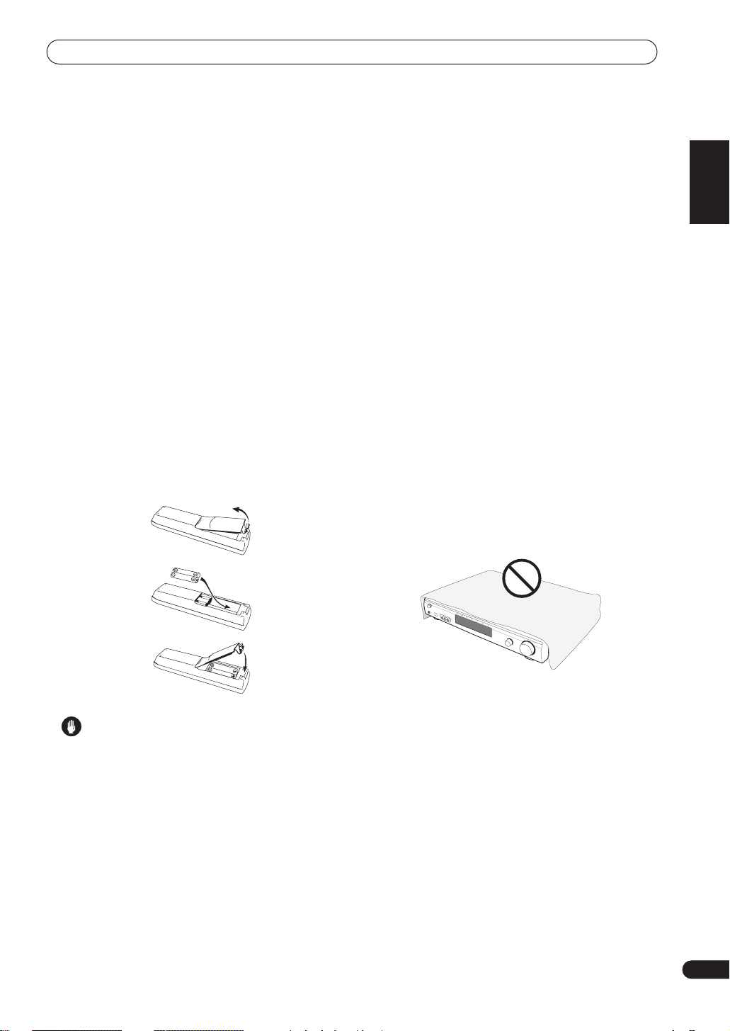
Loading the batteries
The remote control operates on two AA batteries
(supplied).
1
English
Ventilation
• When installing this unit, make sure to leave space
around the unit for ventilation to improve heat
dispersal (at least 20 cm at the top, 50 cm at the rear,
and 10 cm at each side). If not enough space is
provided between the unit and walls or other
equipment, heat will build up inside, interfering with
performance and/or causing malfunctions. See
below for exceptions to this.
• Don’t place anything on top of the receiver except for
a Pioneer DV-667A, 466, 366, 266, 566K, 676A, 575K
or 373 DVD player. If you do place one of these pieces
of equipment on top of the receiver be sure to leave
the ventilation space over it as prescribed above.
• If using a rack to hold the receiver make sure the
back of the rack and the left side are open.
• Also, if you’re using a case with doors, leave the
doors open when using the receiver.
• Do not place on a thick carpet, bed, sofa or fabric
having a thick pile. Do not cover the receiver with
fabric or other covering. Anything that blocks
ventilation will cause the internal temperature to rise,
which may lead to breakdown or fire hazard.
2
3
Caution
• Incorrect use of batteries may result in such hazards
as leakage and bursting. Observe the following
precautions:
• Never use new and old batteries together.
• Insert the plus and minus sides of the batteries
properly according to the marks in the battery case.
• Batteries of the same shape may have different
voltages. Do not use different batteries together.
• When disposing of used batteries, please comply
with governmental regulations or environmental
public institution’s rules that apply in your country or
area.
• The receiver may become hot while in use, please
take care around it.
Maintenance of external surfaces
• Use a polishing cloth or dry cloth to wipe off dust and
dirt.
• When the surfaces are dirty, wipe with a soft cloth
dipped in some neutral cleanser diluted five or six
times with water, and wrung out well, and then wipe
again with a dry cloth. Do not use furniture wax or
cleansers.
• Never use thinners, benzine, insecticide sprays or
other chemicals on or near this unit, since these will
corrode the surfaces.
3
En

Contents
Before you start
Checking the supplied accessories
Loading the batteries
Ventilation
Maintenance of external surfaces
. . . . . . . . . . . . . . . . . . . . . . . . . . . . . . . . . 3
. . . . . . . . . . . . . . . . . . . . . . . . . 3
. . . . . . . . . . . . . . 3
. . . . . . . . . . . . . . . 3
01 Quick start guide
Introduction
Easy Setup
Connecting speakers
Connecting your TV and DVD player
Switching on and playing a DVD
. . . . . . . . . . . . . . . . . . . . . . . . . . . . . . . . 5
. . . . . . . . . . . . . . . . . . . . . . . . . . . . . . . . . 5
. . . . . . . . . . . . . . . . . . . . . . . . 5
. . . . . . . . . . . . 6
. . . . . . . . . . . . . . . . 6
02 Introductory information
Introduction to home theater
Features
. . . . . . . . . . . . . . . . . . . . . . . . . . . . . . . . . . . 7
. . . . . . . . . . . . . . . . . . . 7
03 Connecting your equipment
Rear panel
Installing the receiver
When making cable connections
Connecting a DVD player
Connecting your TV
Connecting a satellite/cable receiver or other
set-top box
Connecting a VCR or DVD recorder
Connecting other video components
Connecting equipment to the front panel inputs
Installing your speaker system
Connecting the speakers
Placing the speakers
Connecting antennas
AM loop antenna
FM wire antenna
Connecting external antennas
Using this receiver with a Pioneer plasma display
Operating other Pioneer components with this unit’s
sensor
Plugging in the receiver
. . . . . . . . . . . . . . . . . . . . . . . . . . . . . . . . . 8
. . . . . . . . . . . . . . . . . . . . . . . . . 9
. . . . . . . . . . . . . . . . 9
. . . . . . . . . . . . . . . . . . . . . 10
. . . . . . . . . . . . . . . . . . . . . . . . . 11
. . . . . . . . . . . . . . . . . . . . . . . . . . . . . . . . 12
. . . . . . . . . . . . . 13
. . . . . . . . . . . . 14
. . . 15
. . . . . . . . . . . . . . . . . 15
. . . . . . . . . . . . . . . . . . . . 16
. . . . . . . . . . . . . . . . . . . . . . . 16
. . . . . . . . . . . . . . . . . . . . . . . . 17
. . . . . . . . . . . . . . . . . . . . . . . . . . 17
. . . . . . . . . . . . . . . . . . . . . . . . . . 17
. . . . . . . . . . . . . . . . 17
. . 18
. . . . . . . . . . . . . . . . . . . . . . . . . . . . . . . . . . . 19
. . . . . . . . . . . . . . . . . . . . . . 19
04 Controls and displays
Front panel
Display
Remote control
Operating range of the remote control
. . . . . . . . . . . . . . . . . . . . . . . . . . . . . . . . 20
. . . . . . . . . . . . . . . . . . . . . . . . . . . . . . . . . . 21
. . . . . . . . . . . . . . . . . . . . . . . . . . . . 22
. . . . . . . . . . 23
05 Getting started
Automatically calibrating your listening area
(MCACC)
Checking the settings on your DVD (or other)
player
Playing a source
. . . . . . . . . . . . . . . . . . . . . . . . . . . . . . . . . 24
MCACC error messages
Other problems when using MCACC
. . . . . . . . . . . . . . . . . . . . . . . . . . . . . . . . . . . . 25
. . . . . . . . . . . . . . . . . . . . . . . . . . . . 26
. . . . . . . . . . . . . . . . . . . . 25
. . . . . . . . . . . 25
06 Home theater sound
Playing multichannel sources
Playing stereo sources
Listening with headphones
Using the Advanced Surround effects
Using the Sound Modes
Enhancing dialog
Using the surround back channel
Listening with virtual surround back speakers
. . . . . . . . . . . . . . . . . . . . . . . . . . . 28
. . . . . . . . . . . . . . . . . . 27
. . . . . . . . . . . . . . . . . . . . . . . 27
. . . . . . . . . . . . . . . . . . . . 28
. . . . . . . . . . . 28
. . . . . . . . . . . . . . . . . . . . . . 28
. . . . . . . . . . . . . . . 29
. . . . 29
07 Using the tuner
Setting the channel step
Finding a station
MPX mode
Tuning directly to a station
Memorizing station presets . . . . . . . . . . . . . . . . . . . 30
Naming station presets . . . . . . . . . . . . . . . . . . . . . 31
Listening to memorized station presets . . . . . . . . . 31
. . . . . . . . . . . . . . . . . . . . . . . . . . . . . . . 30
. . . . . . . . . . . . . . . . . . . . . . 30
. . . . . . . . . . . . . . . . . . . . . . . . . . . . 30
. . . . . . . . . . . . . . . . . . . . 30
08 Using other functions
Selecting the input signal type . . . . . . . . . . . . . . . . . 32
Using the sleep timer . . . . . . . . . . . . . . . . . . . . . . . . 32
Resetting the system . . . . . . . . . . . . . . . . . . . . . . . . 33
Default receiver settings. . . . . . . . . . . . . . . . . . . . . 33
09 The System Setup menu
Making receiver settings from the System Setup
menu . . . . . . . . . . . . . . . . . . . . . . . . . . . . . . . . . . . . 34
Setup menu options . . . . . . . . . . . . . . . . . . . . . . . . 34
SR+ control for Pioneer plasma displays . . . . . . . . 36
Using the SR+ mode with a Pioneer plasma
display . . . . . . . . . . . . . . . . . . . . . . . . . . . . . . . . . . 37
Setting individual channel levels . . . . . . . . . . . . . . 37
10 Controlling other equipment
Using the remote control with other components. . . 38
Recalling preset codes . . . . . . . . . . . . . . . . . . . . . . 39
Resetting all remote control settings . . . . . . . . . . . 39
VCR / DVD / LD player and DVD recorder
controls . . . . . . . . . . . . . . . . . . . . . . . . . . . . . . . . . 40
Cable TV / satellite TV / digital TV / TV controls . . . . 41
Preset code list . . . . . . . . . . . . . . . . . . . . . . . . . . . . . 42
11 Additional information
Troubleshooting . . . . . . . . . . . . . . . . . . . . . . . . . . . . 43
Surround sound formats. . . . . . . . . . . . . . . . . . . . . . 46
Dolby Digital. . . . . . . . . . . . . . . . . . . . . . . . . . . . . . 46
Dolby Digital Surround EX . . . . . . . . . . . . . . . . . . . 46
Dolby Pro Logic IIx and Dolby Surround . . . . . . . . . 46
DTS Digital Surround . . . . . . . . . . . . . . . . . . . . . . . 47
DTS-ES . . . . . . . . . . . . . . . . . . . . . . . . . . . . . . . . . . 47
DTS Neo:6 . . . . . . . . . . . . . . . . . . . . . . . . . . . . . . . 47
DTS 96/24. . . . . . . . . . . . . . . . . . . . . . . . . . . . . . . . 47
PCM (Pulse Code Modulation) . . . . . . . . . . . . . . . . 47
Specifications. . . . . . . . . . . . . . . . . . . . . . . . . . . . . . 48
4
En
Quick start guide
01
Chapter 1
Quick start guide
Introduction
This ‘Quick start guide’ shows you how to connect your
speakers, TV and DVD player to this receiver, and also
takes you through switching on and playing a DVD disc.
Easy Setup
This section shows you how to connect your speakers,
subwoofer, DVD player and TV to this receiver so you can
start enjoying home cinema sound right away.
Before you start, make sure everything you’re connecting
is switched off and unplugged.
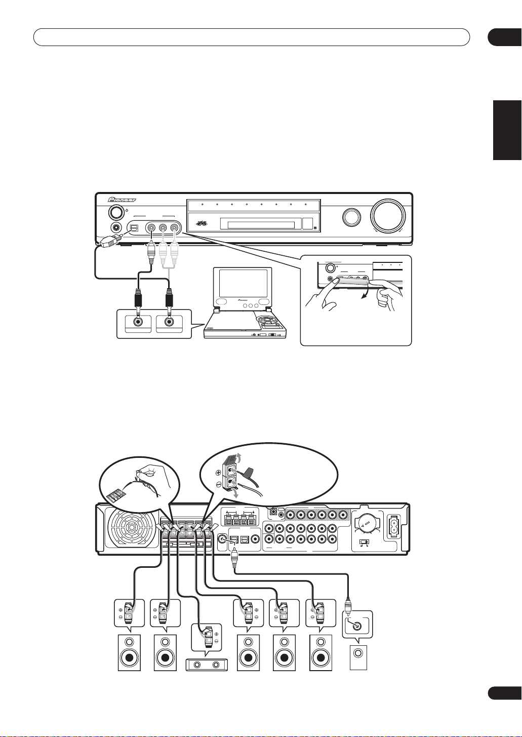
Connecting speakers
This receiver has speaker terminals for front left and right
speakers (
two surround speakers (
speaker (
the front left/right speakers, but we recommend
connecting all five if possible. Note that surround
speakers should always be connected as a pair; do not
connect just one surround speaker. All the speakers you
use should have a nominal impedance between 6–16
L
and R in the diagram), a center speaker (C),
RS
and LS) and a surround back
SB
). The minimum speaker configuration is just
Ω.
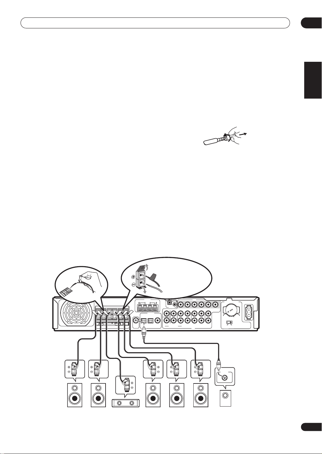
1 Connect your speakers to the receiver, as shown
in the diagram below.
Prepare the speaker cable by stripping about 1 cm of the
plastic shielding from each speaker wire.
Connect the front speakers to the
the center speaker to the
surround speakers to the
CENTER
SURROUND L/R
the surround back speaker to the
FRONT L/R
terminals;
terminals; the
terminals; and
SURROUND BACK
terminals.
Press on a tab to open a terminal; insert the exposed
wire, then release the tab to secure.
For correct sound it’s important that the positive and
negative terminals of the receiver and each speaker are
matched. To help you do this, attach the supplied colored
self-adhesive labels to one half of each speaker cable.
2 Connect a powered subwoofer to the
SUBWOOFER OUT jack, as shown in the diagram
below.
Use a standard audio cable with RCA/phono plugs.
English
See following page for
connection details.
R CENTER
LRL
FRONT
SPEAKERS
SURROUND
SURROUND
ANTENNA
AM LOOP
FM UNBAL 75Ω
+
–
BACK
DIGITAL IN
TV/SAT
DVR/VCR
SUB
(DVD)
WOOFER
OPT1
OPT2
OUT
OUT
IN
CONTROL
CENTER SURROUND
DVD
SUB WOOFER
(TV/SAT)
AUDIO IN (5.1CH)
COAX
VIDEO
IN
IN
IN
FRONT
L
R
DVD
OUT
L
L
R
R
DVR/VCR
TV/SAT
AUDIO
VIDEO
IN
MONITOR
OUT
TWO VOLTAGE SELECTORS
220 -230V 240V
110V
110V
120 -127V
VSX-C502
LINE LEVEL
INPUT
RLC RSLSSBSW
AC IN
120-127V
220 -230V
240V
5
En
01
Quick start guide
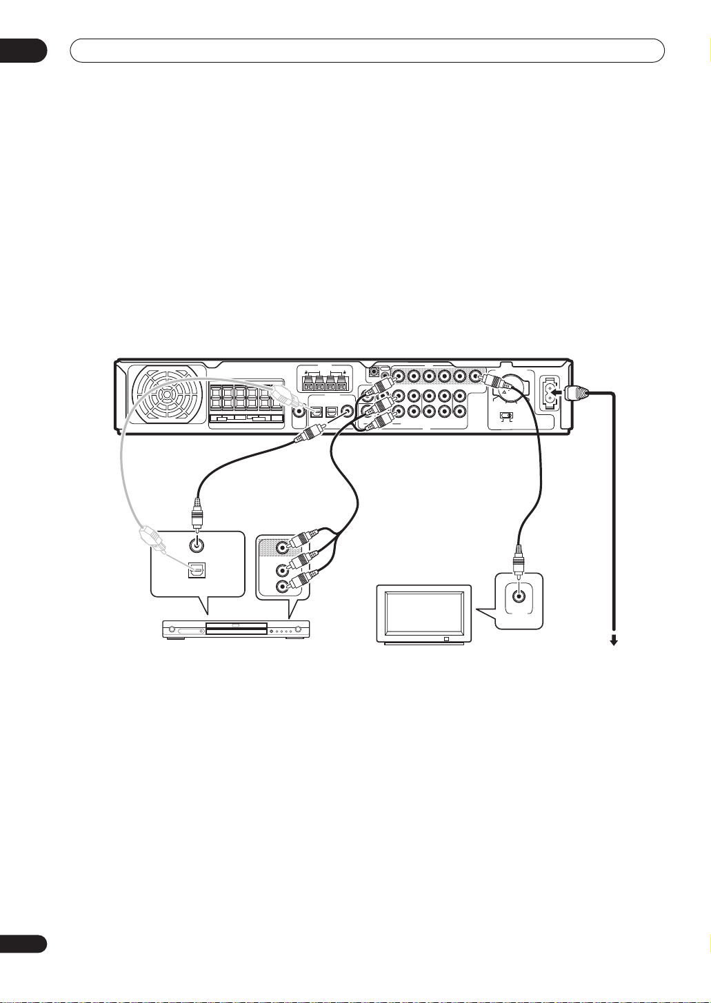
Connecting your TV and DVD player
1 Connect your DVD player to the receiver.
Connect a 3-pin AV cable (not supplied) between the
audio/video outputs of your DVD player and the
jacks of this receiver for the video and analog audio.
For digital audio, connect a coaxial digital audio cable
(not supplied) between your DVD player’s coaxial digital
output and the
DVD(TV/SAT) COAX
jack on this
receiver.
• If your DVD player doesn’t have a coaxial digital out
you can use an optical cable connected between the
optical output jack on your DVD player and the
SAT(DVD) OPT1
VSX-C502
jack on this receiver. However, you
LRL
SURROUND
SPEAKERS
SURROUND
R CENTER
FRONT
DVD IN
TV/
ANTENNA
AM LOOP
FM UNBAL 75Ω
+
–
BACK
DIGITAL IN
TV/SAT
DVR/VCR
SUB
(DVD)
WOOFER
OUT
(TV/SAT)
OPT1
OPT2
will have to reassign the input to DVD before using
for the first time. See
Optical input setting
for how to do this.
• If you connect an optical digital cable, be careful
when inserting the plug not to damage the shutter
protecting the optical socket.
2 Connect your TV to the receiver.
Use a standard video cable (not supplied) to connect the
MONITOR OUT
video jack on this receiver to a video
input on your TV.
3 Connect the supplied AC power cable to the AC
IN on this receiver and plug in the other end to a
power outlet.
L
R
IN
FRONT
DVD
VIDEO
IN
L
R
TV/SATINDVR/VCR
AUDIO
TWO VOLTAGE SELECTORS
MONITOR
IN
OUT
OUT
L
220 -230V 240V
120 -127V
110V
110V
R
VIDEO
AC IN
120-127V
220 -230V
240V
OUT
IN
CONTROL
CENTER SURROUND
DVD
SUB WOOFER
AUDIO IN (5.1CH)
COAX
on page 36
6
En
COAXIAL
OPTICAL
DIGITAL AUDIO OUT
AUDIO
VIDEO
L
R
DVD player
Switching on and playing a DVD
Once you switch the receiver on it will automatically
detect the speakers you have connected. Although there
are a number of more detailed settings you can make to
optimize the surround sound, you should be able to get
acceptable surround sound performance right away.
1 Switch on your TV and powered subwoofer.
Also make sure that your TV is set to the AV input you
connected the receiver to.
2 Press RECEIVER on the remote or STANDBY/
ON on the front panel to switch on the receiver.
3 Press DVD on the remote or turn the INPUT
SELECTOR knob on the front panel to select the DVD
input.
4 Switch on your DVD player.
5 Load a DVD and start playback.
VIDEO
TV
This receiver will automatically decode Dolby Digital,
DTS, or Dolby Surround DVD-Video discs, according to
your speaker setup. In most cases, you won’t have to
make changes for realistic surround sound.
Other possibilities (like listening to a CD with
multichannel surround sound) are explained in
theater sound
on page 27.
Home
6 Use the MASTER VOLUME control (front panel or
remote) to adjust the volume.
• Turn down your TV’s volume so that you only hear
sound from this system.

Introductory information
02
Chapter 2
Introductory information
Introduction to home theater
You are probably used to using stereo equipment to listen
to music, but may not be used to home theater systems
that give you many more options (such as surround
sound) when listening to soundtracks.
Home theater refers to the use of multiple audio tracks to
create a surround sound effect, making you feel like
you're in the middle of the action or concert. The
surround sound you get from a home theater system
depends not only on the speakers you have set up in your
room, but also on the source and the sound settings of
the receiver.
DVD-Video has become the basic source material for
home theater due to its size, quality, and ease of use. The
true multichannel audio possible using DVD is what
creates a convincing surround sound effect and gives
you the feeling of ‘being there’.
Features
Dolby Digital and DTS decoding, including Dolby
Digital EX, DTS 96/24 and DTS-ES
Dolby Digital and DTS decoding brings theater sound
right into your home with up to six channels of surround
sound, including a special LFE (Low Frequency Effects)
channel for deep, realistic sound effects.
With the addition of a surround back speaker, you can
take advantage of the built-in Dolby Digital EX and DTSES decoders for seven channel surround sound.
Multichannel analog inputs
The addition of multichannel analog inputs means total
compatibility with DVD-Audio and other high-resolution
formats, as well as giving you the option of using an
external decoder for Dolby Digital and DTS sources.
(pages 27, 46, 47)
(page 10)
Surround and Advanced Surround modes
(pages 27, 28)
Used together with the Dolby Digital, DTS or Dolby Pro
Logic IIx modes, the Surround and Advanced Surround
modes are designed to enhance particular types of
program material by, for example, reproducing the
acoustic space of a concert hall for music-based
material.
Dialog Enhancement
Use the Dialog Enhancement feature to accentuate
dialog and vocals in a program source and match the
vertical placement of the center channel with the front
left/right channels.
Sound Modes
The Sound Modes offer useful effects for a number of
situations. For example, Midnight mode is useful when
you need to listen at low volume but still want effective
surround sound.
(page 28)
Easy-to-use remote control
The remote control gives you not only complete control
over every function of this receiver, but also over other
components in your home theater system. Using a
system of preset codes, you can program the remote to
operate a wide range of other equipment.
Easy setup
Setting up for home theater sound is as easy as
connecting your speakers, a DVD player or other source,
and your TV. The MCACC (Multichannel Acoustic
Calibration) system quick but accurate surround sound
setup, while for complete surround sound control you
still have access to the full range of surround sound
settings.
(page 24)
English
(page 28)
Dolby Pro Logic IIx and DTS Neo:6 decoders
(pages 27, 46, 47)
The built-in Dolby Pro Logic IIx and DTS Neo:6 decoders
not only provide full surround sound decoding for Dolby
Surround sources, but will also generate convincing
surround sound for any stereo source.
SR+ operation with Pioneer plasma displays
(page 18)
If you have a Pioneer plasma display you can take
advantage of the SR+ features, such as automatic input
switching with the receiver and on-screen displays for
receiver information.
The Energy-saving Design
This unit is designed to use less than 0.4 W of energy
when the receiver is in standby mode.
Manufactured under license from Dolby Laboratories.
“Dolby”, “Pro Logic”, “Surround EX” and the double-D
symbol are trademarks of Dolby Laboratories.
“DTS”, “DTS-ES Extended Surround”, “Neo:6” and “DTS 96/
24“ are trademarks of Digital Theater Systems, Inc.
7
En

03
Connecting your equipment
Chapter 3
Connecting your equipment
Rear panel
8
En
1 2
+
–
R CENTER
LRL
FRONT
SPEAKERS
SURROUND
SURROUND
BACK
R CENTER
LRL
FRONT
SPEAKERS
VSX-C502
SUB
WOOFER
OUT
5 6
SURROUND
SURROUND
ANTENNA
AM LOOP
FM UNBAL 75Ω
+
–
BACK
SUB
WOOFER
OUT
DIGITAL IN
TV/SAT
DVR/VCR
(DVD)
OPT1
OPT2
3 4
ANTENNA
AM LOOP
FM UNBAL 75Ω
DIGITAL IN
TV/SAT
DVR/VCR
DVD
(DVD)
(TV/SAT)
COAX
OPT1
OPT2
DVD
(TV/SAT)
COAX
7 8
Important
• Before making or changing the connections, switch
off the power and disconnect the power cable from
the power outlet.
1 SPEAKERS terminals
FRONT L/R, CENTER, SURROUND L/R
BACK
speaker terminals.
(page 15)
and
SURROUND
2 Antenna connections
AM LOOP
(page 17)
Connect the supplied AM loop antenna or an outdoor
antenna if reception is bad.
FM UNBAL 75Ω antenna terminal
(page 17)
Connect the supplied FM wire or an outdoor antenna
if reception is bad.
3 CONTROL IN jack / CONTROL OUT jack
Use to link Pioneer components together to enable all
components in the chain to use just one remote control
sensor (page 19).
Also used for special SR+ control of Pioneer plasma
displays (page 18).
4 AC IN
(page 19)
Connect the supplied AC power cable.
5 SUBWOOFER OUT jack
(page 15)
Connect a powered (active) subwoofer.
110V
MONITOR
AC IN
AC IN
120-127V
220 -230V
240V
TWO VOLTAGE SELECTORS
OUT
220 -230V 240V
110V
120-127V
220 -230V
110V
240V
120 -127V
IN
IN
CONTROL
CONTROL
IN
CONTROL
CENTER SURROUND
SUB WOOFER
AUDIO IN (5.1CH)
CENTER SURROUND
SUB WOOFER
OUT
OUT
OUT
L
R
AUDIO IN (5.1CH)
IN
FRONT
DVD
FRONT
L
R
DVD
VIDEO
IN
L
R
TV/SATINDVR/VCR
AUDIO
IN
IN
TV/SATINDVR/VCR
TWO VOLTAGE SELECTORS
MONITOR
IN
OUT
OUT
L
220 -230V 240V
R
110V
VIDEO
120 -127V
VIDEO
IN
OUT
L
L
R
R
VIDEO
AUDIO
6 Digital connections
The three digital audio jacks are all inputs. Connect to the
digital outputs of digital source components such as
DVD and CD players, satellite receivers, etc.
TV/SAT(DVD) OPT1 jack
Optical digital audio jack for the
(page 12)
TV/SAT
(although it is possible to reassign it to the
input).
DVR/VCR OPT2 jack
Optical digital audio jack for the
(page 13)
DVR/VCR
• When connecting optical cables, be careful when
inserting the plug not to damage the shutter
protecting the optical socket.
• When storing optical cable, coil loosely. The cable
may be damaged if bent around sharp corners.
DVD(TV/SAT) COAX jack
Coaxial digital audio jack for the
it is possible to reassign it to the
(page 10)
DVD
TV/SAT
input (although
input
DVD
input.
input).

Connecting your equipment
03
7 Audio/Video connections
DVD
(page 12)
(page 2)
(page 10)
input.
TV/SAT
(page 13)
DVR/VCR
DVR/VCR OUT
VIDEO
(page 11)
input.
input.
jacks.
input.
AUDIO IN (5.1CH) jacks
Multichannel analog audio RCA/phono jack
connections for the
TV/SAT IN jacks
RCA/phono jack connections for the
DVR/VCR IN/OUT jacks
RCA/phono jack connections for the
When the receiver is set to any other input, that
signal is output from the
VIDEO IN jacks
RCA/phono jack connections for the
MONITOR OUT video jack
RCA/phono video jack connection for your TV.
8 Voltage Selector
Use to match the voltage coming into the receiver with
the voltage in your country or region.
(page 14)
Installing the receiver
• When installing this unit, make sure to put it on a
secure and level plane that is stable.
• Don’t place it on the following places:
– on a color TV (the screen may distort)
– near a cassette deck (or close to a device that gives
off a magnetic field). This may interfere with the
sound.
– in direct sunlight
– in damp or wet areas
– in extremely hot or cold areas
– in places where there is a vibration or other
movement
– in places that are very dusty
– in places that have hot fumes or oils (such as a
kitchen)
English
When making cable connections
Be careful not to arrange cables in a manner that bends
the cables over the top of this unit. If the cables are laid
on top of the unit, the magnetic field produced by the
transformers in this unit may cause a humming noise to
come from the speakers.
9
En
03
Connecting your equipment
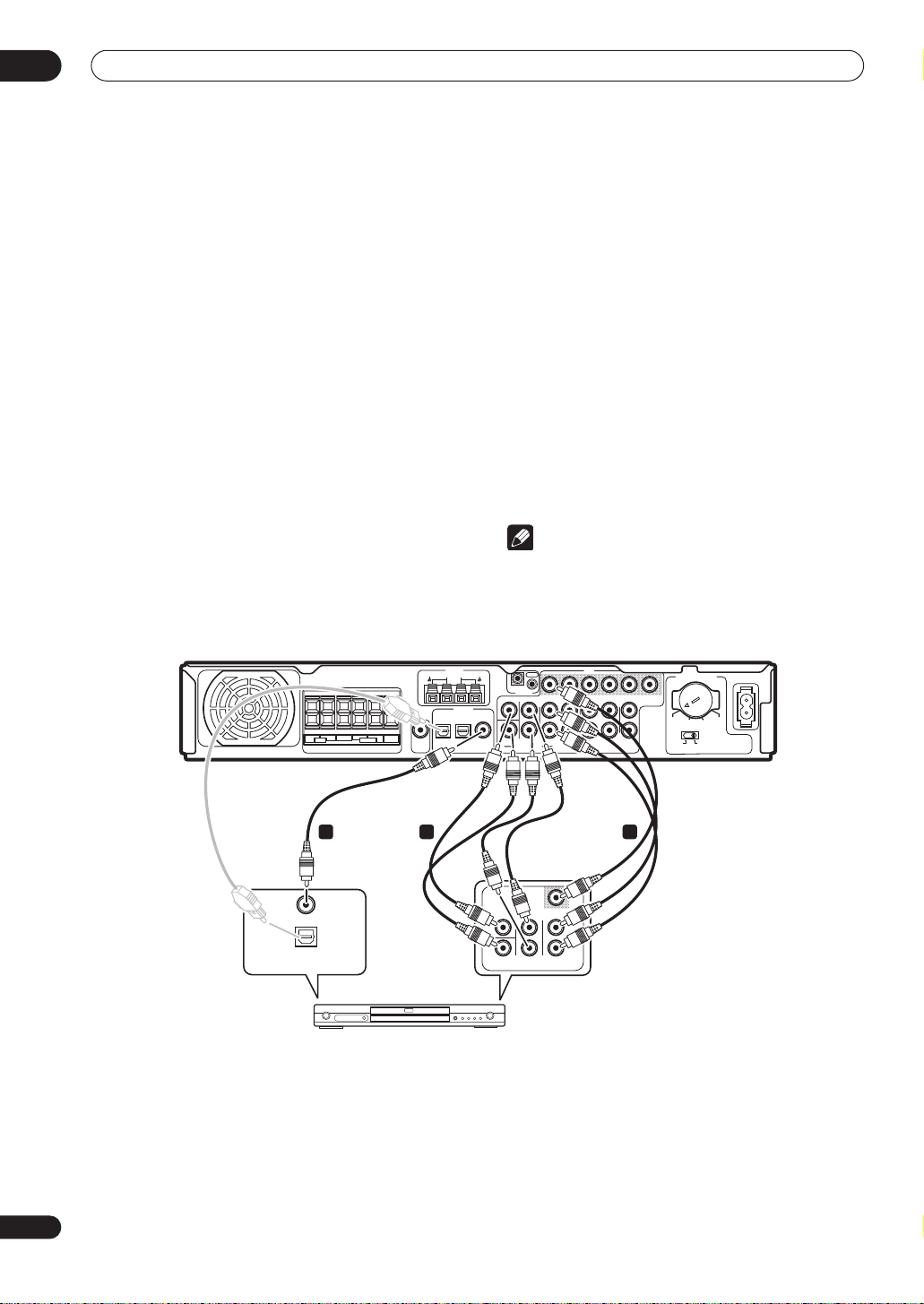
Connecting a DVD player
Follow the instructions below, referring to the diagram, to
connect a DVD player.
If your DVD player has multichannel analog audio
outputs you can connect them to the
jacks on this receiver. Connecting these can be useful as
some discs do not allow digital output from the player. It
can also be useful if you want to use an external digital
decoder unit.
1 Use a stereo audio cable to connect the
FRONT L / R DVD IN jacks to the stereo or front left/
right audio outputs on your DVD player.
If your DVD player has only stereo analog audio outputs,
the jacks are probably labelled something like
OUT L / R
outputs, use the
. If your DVD player has multichannel analog
FRONT L / R
2 If your DVD player has multichannel analog
outputs, connect these to the SURROUND L / R,
CENTER and SUBWOOFER jacks on this receiver.
These connections are shown in 2 in the illustration
below.
AUDIO IN (5.1CH)
AUDIO
jacks.
3 Use a coaxial digital audio cable to connect the
DVD(TV/SAT) COAX jack to a coaxial digital audio
output on your DVD player.
This connection carries stereo and multichannel digital
audio.
If your DVD player doesn’t have a coaxial digital audio out
jack, it is possible to use an optical connection to the
SAT(DVD) OPT1
input is assigned to the
reassign it to the
connecting up everything else see
jack. However, since by default this
TV/SAT
input, you will need to
DVD
input before you can use it. After
Optical input setting
on page 36 for how to do this.
4 Use a video cable to connect the DVD VIDEO IN
jack on this receiver to your DVD players video
output.
This connection is shown in 1 in the illustration below.
Note
• To listen to multichannel analog audio you’ll need to
switch the input signal selector to
(multichannel analog). See
type
on page 32.
DVD 5.1ch
Selecting the input signal
TV/
VSX-C502
R CENTER
LRL
FRONT
SPEAKERS
SURROUND
SURROUND
ANTENNA
AM LOOP
FM UNBAL 75Ω
+
–
BACK
DIGITAL IN
TV/SAT
DVR/VCR
SUB
(DVD)
WOOFER
OPT1
OPT2
OUT
OUT
IN
CONTROL
CENTER SURROUND
DVD
SUB WOOFER
(TV/SAT)
AUDIO IN (5.1CH)
COAX
R
L
IN
FRONT
DVD
VIDEO
IN
L
R
TV/SATINDVR/VCR
AUDIO
TWO VOLTAGE SELECTORS
MONITOR
IN
OUT
OUT
L
220 -230V 240V
120 -127V
110V
110V
R
VIDEO
AC IN
120-127V
220 -230V
240V
13 2
VIDEO
COAXIAL
OPTICAL
DIGITAL AUDIO OUT
CENTER
L
R
FRONTSURR.SUB W.
DVD player
.
10
En
Connecting your equipment
03
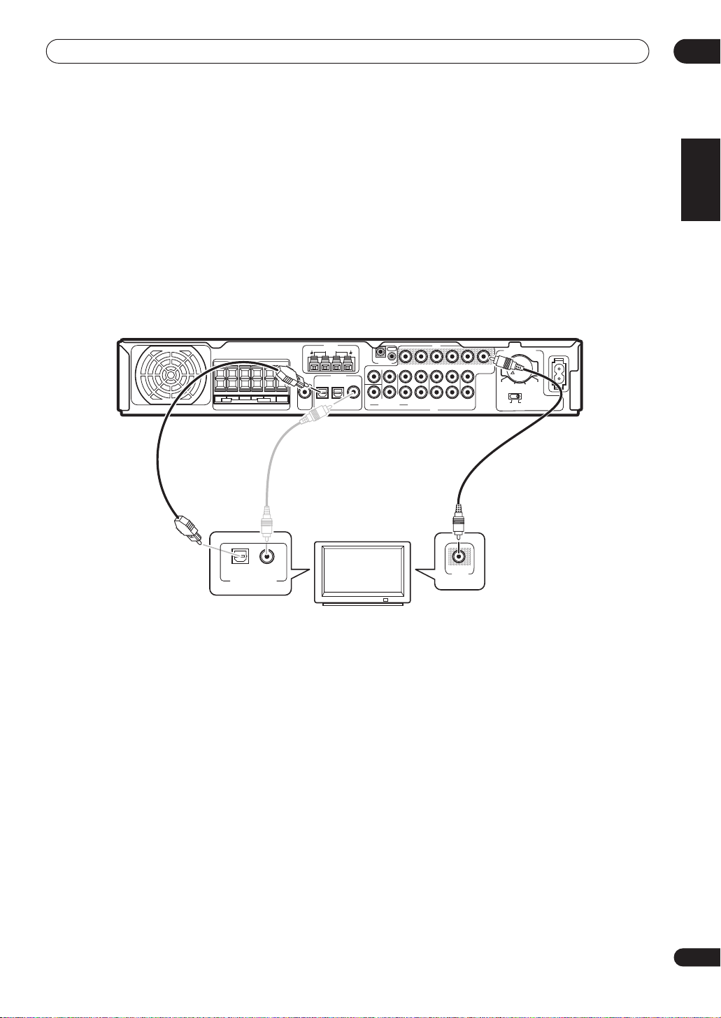
Connecting your TV
This page shows you how to connect your TV to the
receiver. If your TV has a built-in digital decoder, you can
connect the digital audio output to this receiver to enjoy
Dolby Digital and DTS sound from digital TV broadcasts.
1 Use a video cable to connect the MONITOR OUT
video jack to a video input on your TV.
VSX-C502
R CENTER
LRL
FRONT
SPEAKERS
SURROUND
SURROUND
BACK
ANTENNA
AM LOOP
+
–
TV/SAT
SUB
(DVD)
WOOFER
OPT1
OUT
2 Use an optical digital audio cable to connect the
TV/SAT(DVD) OPT1 jack to an optical digital audio
output on your TV.
If your TV doesn’t have an optical digital audio out jack, it
is possible to use a coaxial connection to the
SAT) COAX
assigned to the
the
TV/SAT
up everything else see
jack. However, since by default this input is
DVD
input, you will need to reassign it to
input before you can use it. After connecting
Optical input setting
on page 36 for
how to do this.
VIDEO
FM UNBAL 75
DIGITAL IN
DVR/VCR
Ω
(TV/SAT)
OPT2
OUT
IN
CONTROL
IN
IN
CENTER SURROUND
FRONT
L
SUB WOOFER
AUDIO IN (5.1CH)
R
DVD
DVD
COAX
L
R
TV/SATINDVR/VCR
AUDIO
OUT
L
R
VIDEO
IN
MONITOR
OUT
TWO VOLTAGE SELECTORS
220 -230V 240V
110V
120-127V
220 -230V
110V
240V
120 -127V
AC IN
English
DVD(TV/
COAXIAL
OPTICAL
DIGITAL AUDIO OUT
VIDEO
IN
TV
11
En
03
Connecting your equipment
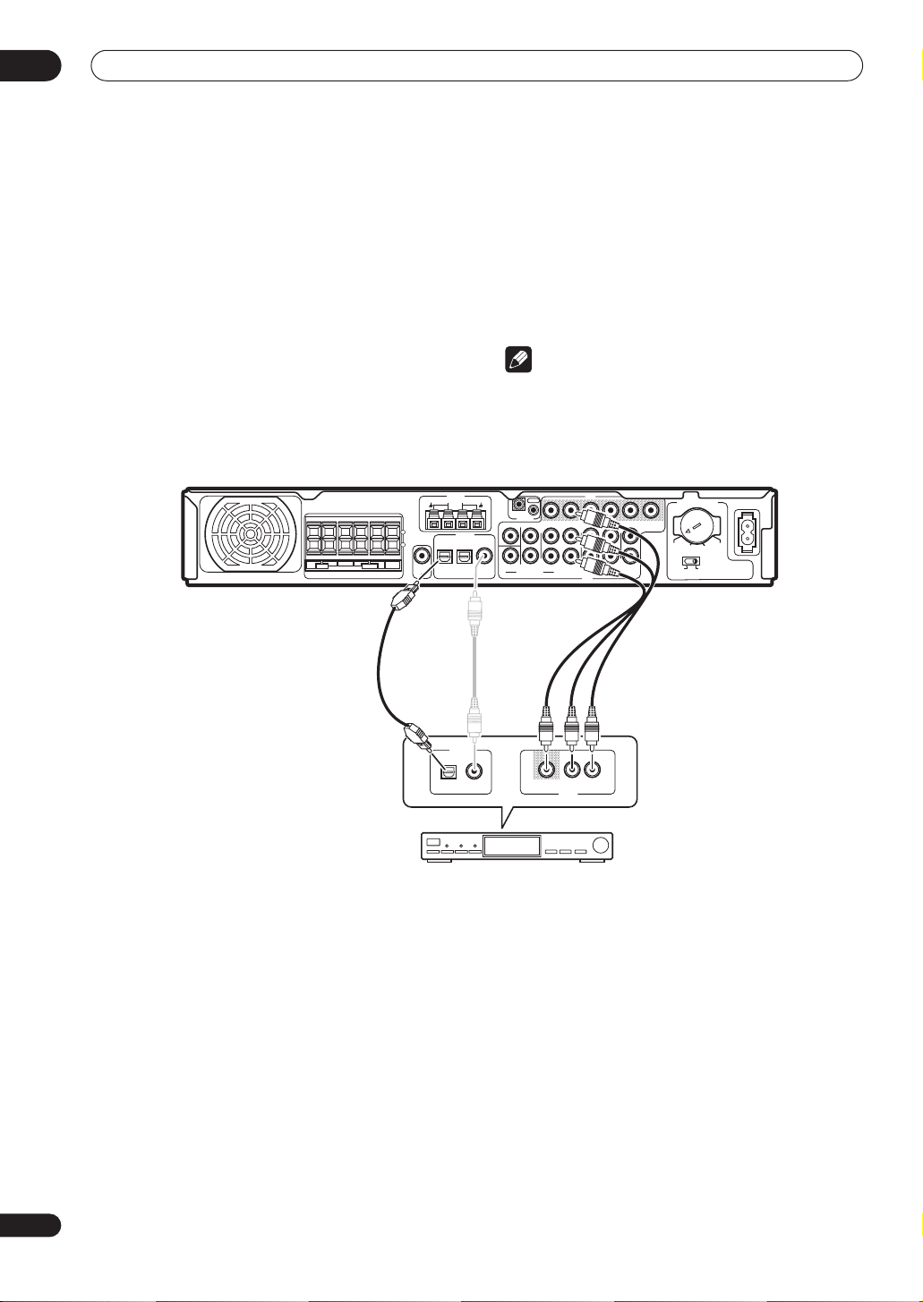
Connecting a satellite/cable receiver or other set-top box
Satellite and cable receivers, and terrestrial digital TV
tuners are all examples of so-called ‘set-top boxes’.
1 Use a 3-pin AV cable to connect the TV/SAT IN
jacks to a set of audio/video outputs on the set-top
box component.
This carries video and analog stereo audio signals from
the set-top box component to this receiver.
2 Use an optical digital audio cable to connect the
TV/SAT(DVD) OPT1 jack to an optical digital audio
output on the set-top box component.
This connection carries stereo and multichannel digital
audio.
+
–
SURROUND
SURROUND
BACK
SUB
WOOFER
OUT
VSX-C502
R CENTER
LRL
FRONT
SPEAKERS
If your set-top box component doesn’t have an optical
digital audio out jack, it is possible to use a coaxial
connection to the
DVD(TV/SAT) COAX
since by default this input is assigned to the
you will need to reassign it to the
TV/SAT
you can use it. After connecting up everything else see
Coaxial input setting
on page 36 for how to do this.
Note
• If your satellite/cable receiver doesn’t have a digital
audio output, omit step
2
above.
• For recording to a DVR/VCR, you must have the settop box connected to this receiver using the standard
video and analog audio
ANTENNA
AM LOOP
FM UNBAL 75Ω
DIGITAL IN
TV/SAT
DVR/VCR
(DVD)
OPT1
OPT2
OUT
IN
CONTROL
CENTER SURROUND
DVD
SUB WOOFER
(TV/SAT)
AUDIO IN (5.1CH)
COAX
VIDEO
IN
IN
IN
FRONT
L
R
DVD
OUT
L
R
DVR/VCR
TV/SAT
AUDIO
L
R
IN
VIDEO
TV/SAT IN
MONITOR
OUT
220 -230V 240V
110V
120 -127V
TWO VOLTAGE SELECTORS
110V
120-127V
220 -230V
240V
jack. However,
DVD
input,
input before
jacks.
AC IN
12
En
STB
DIGITAL OUT
VIDEO AUDIOL
R
AV OUT
Connecting your equipment
03
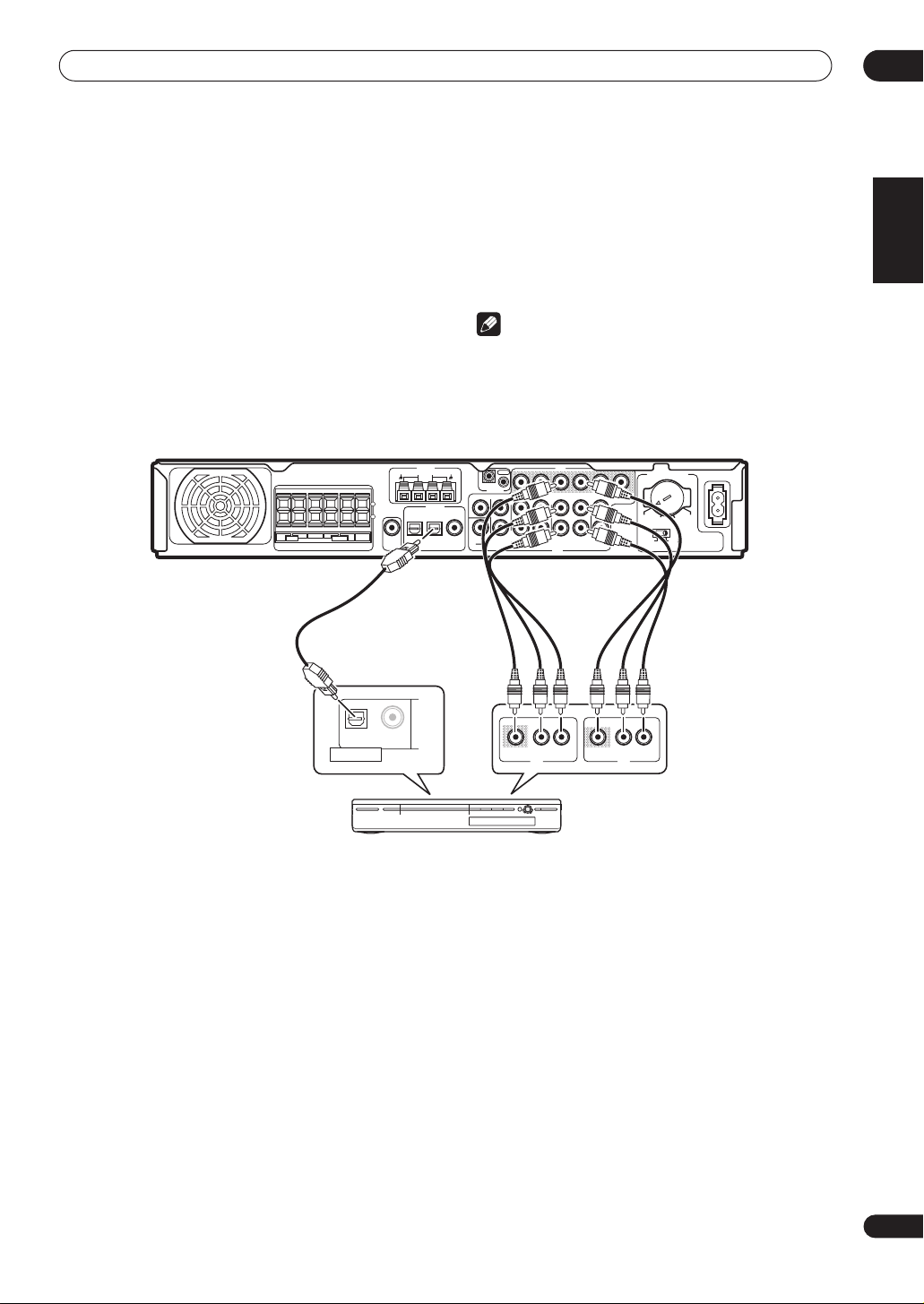
Connecting a VCR or DVD recorder
For video recording, connect a VCR or DVD recorder to
the
DVR/VCR IN/OUT
optical digital input means that you can play digital
sound tracks from a DVD (or other digital) recorder.
1 Use two 3-pin AV cables to connect the DVR/VCR
IN/OUT jacks to a set of audio/video input/output
jacks on your VCR, DVD recorder (or other video
component).
This allows playback from and recording to the VCR/DVR
(or other component).
VSX-C502
jacks. The
DVR/VCR OPT2
SURROUND
SURROUND
BACK
R CENTER
LRL
FRONT
SPEAKERS
jack for
+
–
SUB
WOOFER
OUT
ANTENNA
AM LOOP
FM UNBAL 75Ω
DIGITAL IN
TV/SAT
DVR/VCR
(DVD)
OPT1
OPT2
2 Use an optical digital audio cable to connect the
DVR/VCR OPT2 jack to an optical digital audio output
on your DVD recorder (or other video component).
This connection carries stereo and multichannel digital
audio.
Note
• If your video component doesn’t have a digital audio
output, omit step
2
above.
• In order to record, you must connect the analog
audio cables (the digital connection is for playback
only).
OUT
IN
CONTROL
CENTER SURROUND
DVD
SUB WOOFER
(TV/SAT)
AUDIO IN (5.1CH)
COAX
VIDEO
IN
IN
IN
FRONT
L
R
DVD
OUT
L
L
R
R
DVR/VCR
TV/SAT
AUDIO
VIDEO
IN
MONITOR
OUT
TWO VOLTAGE SELECTORS
220 -230V 240V
110V
120-127V
220 -230V
110V
240V
120 -127V
AC IN
English
OPTICAL COA XIAL
DIGITAL OUT
DVR, VCR, etc.
VIDEO AUDIOLR
AV OUT
VIDEO AUDIOLR
AV IN
13
En

03
Connecting your equipment
Connecting other video components
The
VIDEO IN
component, including video players, TV games and so
on. Note that there is no digital audio input for this set of
jacks.
1 Use a 3-pin AV cable to connect the VIDEO IN
jacks to a set of audio/video output jacks on your
VCR or other video component.
This allows playback from the other component.
jacks can be used with any kind of video
VSX-C502
R CENTER
LRL
FRONT
SPEAKERS
ANTENNA
AM LOOP
FM UNBAL 75Ω
SURROUND
SURROUND
+
–
BACK
DIGITAL IN
TV/SAT
DVR/VCR
SUB
(DVD)
WOOFER
OUT
(TV/SAT)
OPT1
OPT2
OPTICAL COA XIAL
DIGITAL OUT
Video player, TV game, etc.
VIDEO
OUT
IN
CONTROL
IN
IN
IN
CENTER SURROUND
FRONT
L
SUB WOOFER
AUDIO IN (5.1CH)
R
DVD
VIDEO AUDIOLR
DVD
COAX
OUT
L
L
R
R
DVR/VCR
TV/SAT
AUDIO
AV OUT
VIDEO
IN
MONITOR
OUT
TWO VOLTAGE SELECTORS
220 -230V 240V
110V
120-127V
220 -230V
110V
240V
120 -127V
AC IN
14
En
Connecting your equipment
03
Connecting equipment to the front panel inputs
The
FRONT INPUT
video jack (
L/R
) and an optical digital audio input (
jacks include a standard (composite)
VIDEO
), stereo analog audio inputs (
DIGITAL
AUDIO
). You can
use these connections for any kind of audio/video
component, but they are especially convenient for
portable equipment such as camcorders, video games
VSX-C502
2
DIGITALSTANDBY
Portable DVD player, etc.
PHONES/SETUP MIC
STANDBY/ON
FRONT INPUT
DIGITAL IN VIDEO AUDIOLR
VIDEO IN/OUT
AUDIO IN/OUT
and portable audio/video equipment.
• Remove the cover to access the front panel jacks.
(See diagram below)
• The illustration below shows example connections to
a portable DVD player.
PHONES
COLORBRIGHT MONITOR
NEO:6
II
2
ADVANCED
PRO LOGIC
IIX
INPUT SELECTOR
PHONES/SETUP MIC
Push where indicated then
PHONES
HOLDON/OFF
pull off from the other side.
2
PRO LOGIC
DTS
DIGITAL OUT (OPTICAL)
Installing your speaker system
To take full advantage of the receiver’s surround sound
capabilities connect front, center, surround and
surround back speakers, as well as a subwoofer.
Although this is ideal, other configurations with fewer
speakers—no subwoofer or no center speaker, or no
surround speakers, or even no surround back speaker—
will work. At the very least, front left and right speakers
only are necessary. Note that surround speakers should
always be connected as a pair; do not connect just one
surround speaker. All the speakers you use should have
a nominal impedance between 6–16
English
MASTER
VOLUME
DOWN
UP
STANDBY/ON
FRONT INPUT
DIGITAL IN
L
VIDEO AUDIO R
P
U
S
H
O
P
E
N
2
DIGITALAV DIRECT
Ω.
See following page for
connection details.
R CENTER
LRL
FRONT
SPEAKERS
SURROUND
SURROUND
ANTENNA
AM LOOP
FM UNBAL 75Ω
IN
CONTROL
DIGITAL IN
DVR/VCR
CENTER SURROUND
DVD
SUB WOOFER
(TV/SAT)
AUDIO IN (5.1CH)
COAX
OPT2
+
–
BACK
TV/SAT
SUB
(DVD)
WOOFER
OPT1
OUT
VIDEO
OUT
IN
IN
IN
FRONT
L
R
DVD
OUT
L
R
DVR/VCR
TV/SAT
AUDIO
TWO VOLTAGE SELECTORS
IN
MONITOR
OUT
L
220 -230V 240V
R
VIDEO
110V
110V
120 -127V
VSX-C502
LINE LEVEL
INPUT
RLC RSLSSBSW
AC IN
120-127V
220 -230V
240V
15
En
 Loading...