


IntelliVue MP
Table of contents
 Loading...
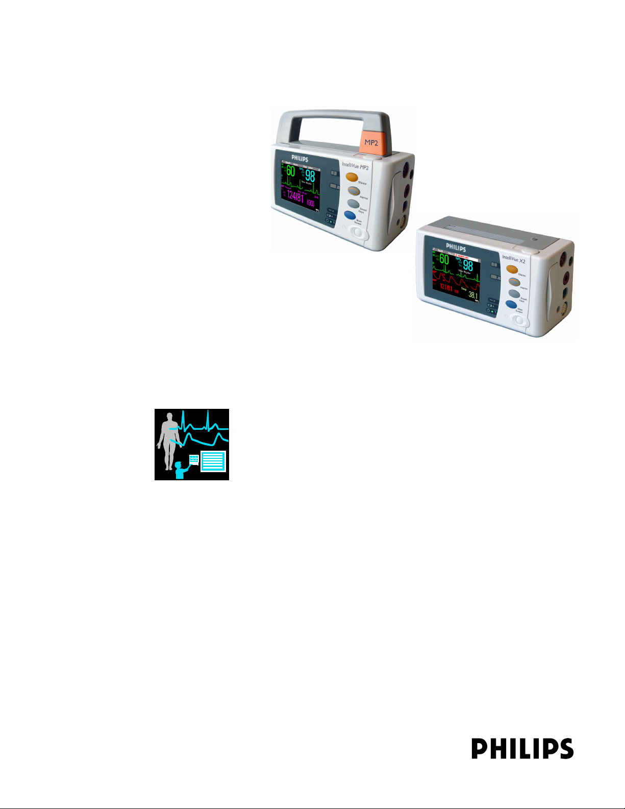
Patient Monitoring
Service Guide
IntelliVue MP2/X2
IntelliVue Patient Monitor
MP2/X2

Part Number M3002-9301B
4535 641 12541
*M3002-9301B*

3
Contents
1 Introduction 9
Who Should Use This Guide 9
How to Use This Guide 9
Responsibility of the Manufacturer 10
Passwords 10
Warnings and Cautions 11
2 Theory of Operation 13
Monitor Theory of Operation 13
System Boundaries 14
Hardware Building Blocks 15
Data Flow 19
How does the Support Tool Work with the Monitor 22
Monitor Software Block Diagram 22
Block Diagram Legend 23
3 Testing and Maintenance 27
Introduction 27
Terminology and Definitions 28
Recommended Frequency 29
When to Perform Tests 30
Testing Sequence 34
Visual Inspection 35
Before Each Use 35
After Each Service, Maintenance or Repair Event 35
Power On Test 35
Safety Tests 36
Warnings, Cautions, and Safety Precautions 37
Safety Test Procedures 38
System Test 62
What is a Medical Electrical System? 62
General Requirements for a System 62
System Example 63
System Installation Requirements 64
Required Protective Measures at System Installation 65
System Test Procedure 75
Preventive Maintenance Procedures 76
Noninvasive Blood Pressure Measurement Calibration 76
Performance Assurance Tests 76
Basic Performance Assurance Test 76

4
Full Performance Assurance Test 77
ECG/Resp Performance Test 77
ECG Sync Performance Test 78
SpO2 Performance Test 78
NBP PerformanceTest 79
Invasive Pressure Performance Test 81
Temperature Performance Test 82
M3014A Capnography Extension Performance Tests 82
Microstream CO2 Performance Test 85
Cardiac Output Performance Test 90
Power Loss Alarm Buzzer Performance Test (only if Multi-Port Nurse Call Connector Board is installed) 92
IntelliVue 802.11 Bedside Adapter Communication Test 92
IIT Communication Test 93
Short Range Radio (SRR) Performance Test 94
Reporting of Test Results 95
Carrying Out and Reporting Tests 95
Evaluation of Test Results 97
Other Regular Tests 98
Locking/Unlocking Touch Operation 98
Battery Handling, Maintenance and Good Practices 98
About the Battery 98
Checking the Battery Status 99
Battery Status on the Main Screen 100
Battery Status Window 101
Checking Battery Charge 103
Replacing a Battery 103
Optimizing Battery Performance 104
Battery Safety Information 108
After Installation, Testing or Repair 108
4 Troubleshooting 109
Introduction 109
How To Use This Section 109
Who Should Perform Repairs 109
Replacement Level Supported 110
Software Revision Check 110
Software Compatibility Matrix 110
Compatibilty with MMS 111
Compatibility with Information Center 111
Obtaining Replacement Parts 111
Troubleshooting Guide 112
Checks for Obvious Problems 112
Checks Before Opening the Instrument 112
Troubleshooting Tables 114

5
Status Log 130
List of Error Codes 131
Troubleshooting with the Support Tool 131
Troubleshooting the Individual Measurements or Applications 131
5 Repair and Disassembly 133
Who Should Perform Repairs 133
Tools required 133
Removing the Battery 134
Removing the Handle 134
Removing the Side Cover 135
Removing the Display/Exchangi ng the SR R B oar d 136
Reassembly of the Display 138
Removing the NBP Pump Assembly 138
Reassembling the NBP pump chassis 140
Exchanging the NBP Pump 142
Exchanging the NBP Airguide / IIT or WLAN Assembly 145
Reassembly Procedure 147
Exchanging the Loudspeaker 150
Reassembly Procedure 151
Removing the Power Board 152
Reassembly Procedure 154
Removing the ECG Sync Pulse Out Connector 155
Removing the Main Board 157
Removing the Rear Housing 158
Removing the Measurements 160
Exchanging the Main Housing 161
Exchanging the Silicon Pads 162
MMS Extensions - Exchanging the Top Cover, MSL Flex Cable and the Dual Link Bar 165
Exchange Procedures 166
Disassembly Procedures for the M3015A MMS Extension (HW Rev. A) 177
Removing the Front Cover 177
Refit Procedures for the MMS Extension 181
Smart Battery Charger LG1480 (M8043A) 183
Cleaning the Air Filter Mats 183
Replacing the Fan 183
6 Parts 187
Exchange and Replacement Parts 189
MMS Extension Parts (M3012A, M3014A, M3015A and M3016A) 192
MMS Extension Part Numbers - Release Mechanisms 192
MMS Extension Part Numbers - Top Cover, Flex Cable and Link Bar 193
MMS Extension Part Numbers - Front Bezels 193
Exchange Parts List 195

6
Smart Battery Charger Part Numbers
197
7 Installation Instructions 199
Out-Of-Hospital Transport - Standards C om pli ance 199
Electromagnetic Interference (SRR) 201
Installation Checklist 201
Unpacking and Checking the Shipment 201
Initial Inspection 202
Claims for Damage 202
Repacking 202
Mounting the Monitor 203
Mounting the Monitor using the Anti-slip Pad 203
Mounting the Monitor using the MMS Mount and Mounting Clamp 205
Connecting the Monitor to AC Mains 209
Host Monitor as Power Source 209
External Power Supply M8023A(Standard with MP2, Optional with X2) 210
Checking Out the Monitor 211
Configuration Tasks 212
Checking Country-Specific Default Settings 212
Setting Altitude, Line Frequency, ECG Cable Colors and Height & Weight Units 213
Configuring the Equipment Label 213
Configuring IP Address, Subnet Mask and Default Gateway 214
Configuration Settings for CSCN Routed Bedside Monitors (RBM) 214
Configuring Routed Bedside Monitors Support 215
Setting the Date and Time 215
Handing Over the Monitor 216
Philips Clinical Network (Wired) 216
Philips IntelliVue Information Center 216
IntelliVue Instrument Telemetry (IIT) 217
Short Range Radio 218
Configuring SRR Channels 218
ECG Sync Pulse 221
MSL Cable Termination 222
8 Site Preparation 225
Introduction 225
Site Planning 225
Roles & Responsibilities 226
Monitor Site Requirements 228
Space Requirements 228
Environmental Requirements 228
Electrical and Safety Requirements (Customer or Philips) 229
Connecting Non-Medical Devices 230
Philips Medical LAN 230

7
9 MP2/X2 Product Structure 231
Upgrades 238
10 Default Settings Appendix 241
Country-Specific Default Settings 241
11 Index 251

8

9
1
1Introduction
This Service Guide contains technical details for the IntelliVue MP2 Patient Monitor and the
IntelliVue X2.
This guide provides a technical foundation to support effective troubleshooting and repair. It is
not a comprehensive, in-depth explanation of the product architecture or technical
implementation. It offers enough information on the functions and operations of the monitoring
system so that engineers who repair them are better able to understand how it works.
Who Should Use This Guide
This guide is for biomedical engineers or technicians responsible for installing, troubleshooting,
repairing, and maintaining Philips’ patient monitoring systems.
How to Use This Guide
This guide is divided into eight sections. Navigate through the tab le of conte nts at the left of the
screen to select the desired topic. Links to other relevant sections are also provided within the
individual topics. In addition, scrolling through the topics with the page up and page down keys
is also possible.

1 Introduction Responsibility of the Manufacturer
10
Responsibility of the Manufacturer
Philips only considers itself responsible for any effects on safety, EMC, reliability and
performance of the equipment if:
- assembly operations, extensions, re-adjustments, modifications or repairs are carried out by
persons authorized by Philips, and
- the electrical installation of the relevant room complies with national standards, and
- the instrument is used in accordance with the instructions for use.
To ensure safety and EMC, use only those Philips parts and accessories specified for use with
the monitor. If non-Philips parts are used, Philips is not liable for any damage that these parts
may cause to the equipment.
This document contains proprietary information which is protected by copyright. All Rights
Reserved. Reproduction, adaptation, or translation without prior written permission is prohibited,
except as allowed under the copyright laws.
Philips Medizin Systeme Böblingen GmbH
Hewlett-Packard Str. 2
71034 Böblingen, Germany
The information contained in this document is subject to change without notice.
Philips makes no warranty of any kind with regard to this material, including, but not limited to,
the implied warranties or merchantability and fitness for a particular purpose.
Philips shall not be liable for errors contained herein or for incidental or consequential damages
in connection with the furnishing, performance, or use of this material.
Passwords
In order to access different modes within the monitor a password may be required. The
passwords are listed below.
Monitoring Mode: No password required
Configuration Mode: 71034
Demo Mode: 14432
Service Mode: 1345
Consult the configuration guide before making any changes to the monitor configuration.

Warnings and Cautions 1 Introduction
11
Warnings and Cautions
In this guide:
- A warning alerts you to a potential serious outcome, adverse event or safety hazard. Failure
to observe a warning may result in death or serious injury to the user or patient.
- A caution alerts you where special care is necessary for the safe and effecti ve use of the
product. Failure to observe a caution may result in minor or moderate personal injury or
damage to the product or other property, and possibly in a remote risk of more serious
injury.

1 Introduction Warnings and Cautions
12

13
2
2Theory of Operation
Monitor Theory of Operation
The IntelliVue MP2/X2 Patient Monitor:
- displays real-time data
- alarms in the case of patient or equipment problems
- offers limited data storage and retrieval (trending)
- interfaces to the Philips Clinical Network and other equipment
The monitor can be configured with various different measurement and interface capabilities.
NOTE
The following descriptions may vary depending on the monitor option purchased.
2 Theory of Operation Monitor Theory of Operation
14
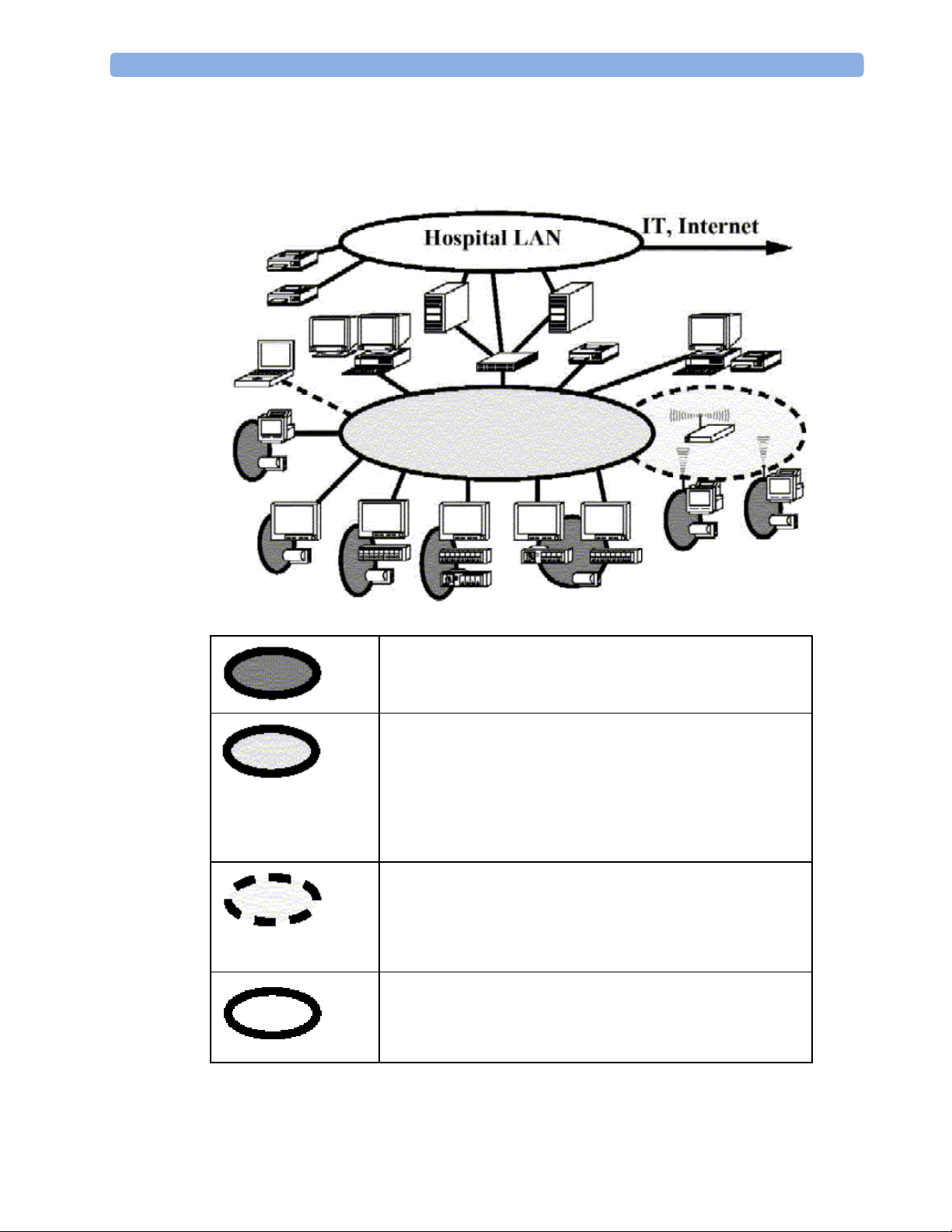
System Boundaries
The following diagram discusses specific boundaries within the overall system with respect to
their openness and real-time requirements:
System Boundaries
Measurement connections
Built-in measurement block
Philips Clinical Network (wired LAN)
connects multiple patient monitors, information centers,
application servers; closed system, only Philips qualified
products (tested and with regulatory approval) are connected,
Philips is responsible for guaranteed real-time functionality and
performance
Philips Clinical Network (wireless)
like Philips Clinical Network (wired) LAN, however due to
current wireless technologies available it has reduced
bandwidth, longer latencies, reduced functionality
Hospital LAN, Internet
Standard Network, not under Philips control, no guaranteed
service, no real-time requirements
Monitor Theory of Operation 2 Theory of Operation
15
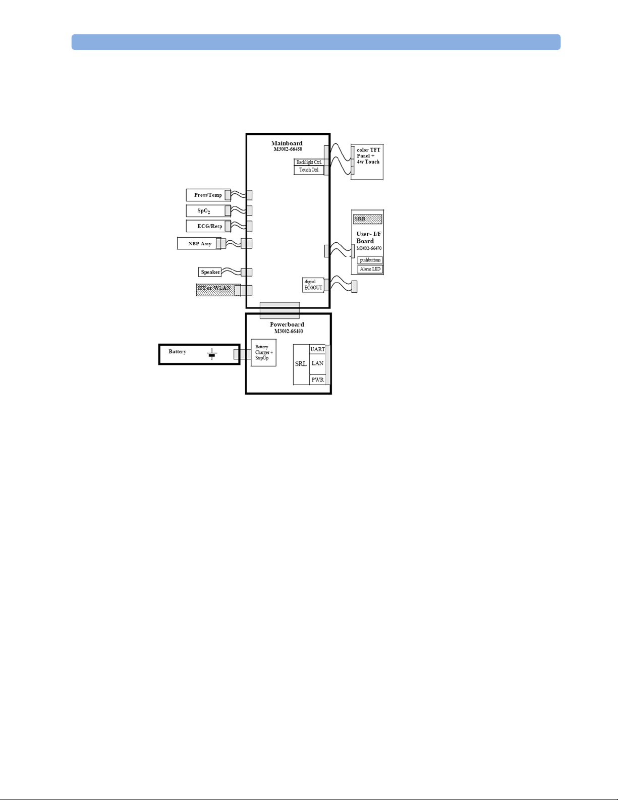
Hardware Building Blocks
The following hardware building blocks make up the monitoring system:
MP2/X2 Hardware Building Blocks
IntelliVue MP2
The MP2 monitor:
- integrates the display and processing unit into a single package
- uses a 3.5” color TFT display
- uses the Touchscreen as input device
- integrates the measurement block with optional parameter sets
- has an internal battery
- standalone patient monitor
2 Theory of Operation Monitor Theory of Operation
16
IntelliVue X2
The IntelliVue X2:
- integrates the display and processing unit into a single package
- uses a 3.5” color TFT display
- uses the Touchscreen as input device
- integrates the measurement block with optional parameter sets
- has an internal battery
- can be used as a Multi-Measurement Module or as a standalone patient monitor
Optional Hardware
- An optional built-in wireless network interface (IntelliVue 802.11 Bedside Adapter or
IntelliVue Instrument Telemetry) is supported. For further details regarding the wireless
network please refer to the M3185A Philips Clinical Network documentation.
- Integrated Short Range Radio (SRR)
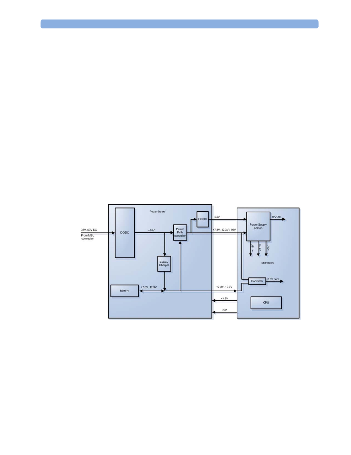
Power Distribution
Power Distribution Architecture

Monitor Theory of Operation 2 Theory of Operation
17
The DC/DC converter transforms the DC power (36-60 V DC range) coming from the MSL plug
into a 16 V DC source and isolates the monitoring system from the DC MSL.
The 16V DC is distributed via the Power Board to the battery charging circuit and to the main
board.
The power is used to charge the battery and supply the monitoring system. As soon as the DC
power source is disconnected, the battery starts and keeps the system powered (battery mode).
The main board contains power supply circuits, which convert the 16 V DC into several voltages
supplying the particular components of the monitoring system.
The realtime clock and the buffered RAM is supplied with cont. 3.6 V DC power, provided
either by the 16 V DC system power or by the battery power and converted to 3.6 V DC.
The CPU board has an MPC852 MHz processor in the patient monitor that provides a number of
on-chip, configurable interfaces. An array of fast UARTS with configurable protocol options are
implemented in an ASIC (along with other system functions such as independent watchdogs,
video, etc.), providing interfacing capabilities to integrated measurements. The main board
contains additional video hardware.
The CPU provides a LAN interface to connect to the Philips Clinical Network (Ethernet).
System Interfaces
The LAN interface on the Measurement Link (MSL) is used as the network interface.
2 Theory of Operation Monitor Theory of Operation
18
Compatible Devices
M3012A, M3014A, M3015A, M3016A MMS Extensions
NOTE
The MMS Extensions are not supported if the IntelliVue MP2/X2 is powered from the internal
battery. Although they can still be attached, they will not function in this case.
Monitor Theory of Operation 2 Theory of Operation
19
Data Flow
The following diagram shows how data is passed through the monitoring system. The individual
stages of data flow are explained below.
Data
Acquisition
Data
Provider
Service
Applications
Display
and User
Interface
Persistent
Data
Storage
Data
Output
Data Flow
Data Acquisition
Monitoring data (for example patient measurement data in the form of waves, numerics and
alerts) is acquired from a variety of sources:
- Measurement Block
The integrated measurements convert patient signals to digital data and apply measurement
algorithms to analyze the signals.
- External measurement devices
Data can be also acquired from devices connected to the monitor. Software modules
dedicated to such specific devices convert the data received from an external device to the
format used internally.
- Server systems on the Philips Clinical Network
To enable networked applications, data can be acquired from server systems attached to the
Philips Clinical Network, for example a Philips Information Center

2 Theory of Operation Monitor Theory of Operation
20
Data Provider System Service
All data that is acquired from integrated measurements or external measurement devices is
temporarily stored by a dedicated data provider system service. All monitor applications use this
central service to access the data in a consistent and synchronized way rather than talking to the
interfaces directly.
This service makes the applications independent of the actual type of data acquisition device.
The amount of data stored in the data provider system service varies for the different data types.
For example several seconds of wave forms and the full set of current numerical values are
temporarily stored in RAM.
Persistent Data Storage System Service
Some applications require storage of data over longer periods of time. They can use the
persistent data storage system service. Dependent on the application requirements, this service
can store data either in battery backed-up (buffered) memory or in flash memory. The buffered
memory will lose its contents if the monitor is without power (not connected to mains) for an
extended period of time. The flash memory does not lose its contents.
The trend application for example stores vital signs data in a combination of flash memory and
buffered memory, while the system configuration information (profiles) is kept purely in flash
memory.
Display and User Interface Service
Applications can use high level commands to display monitoring data or status and command
windows on the internal LCD panel. These commands are interpreted by the display manager
application. This application controls the dedicated video hardware which includes video
memory and a special hardware in the ASIC.
User input is acquired from the touchscreen. The system software makes sure that the user input
is directed to the application which has the operating focus.
Monitor Applications
The monitor applications provide additional system functionality over the basic measurement
and monitoring capabilities. This includes for example trending, report generating, event storage
or derived measurements.
In general, the monitor applications use the data provider system service to access the
measurement data. Application interfaces to the other system services allow the application to
visualize data, to store data over extended periods of time or to output data to other devices.

Monitor Theory of Operation 2 Theory of Operation
21
Internal LAN (Measurement Link)
The MP2/X2 communicates using an IEEE802.3 Ethernet LAN in the Measurement Link
(MSL). This network is used to distribute data between the components, for exam ple:
- Digitized patient signals including wave data, numerical data and status information
(typically from the measurement server to a display unit)
- Control data representing user interactions (typically from the display unit to a measurement
server)
- Shared data structures, for example representing patient demographical data and global
configuration items
The internal LAN allows plug and play configuration of the monitoring system. The system
automatically detects plugging or unplugging of measurement servers and configures the system
accordingly.
The components on the internal LAN are time-synchronized to keep signal data consistent in the
system. Dedicated hardware support for synchronization eliminates any latency of the network
driver software.
The integrated LAN provides deterministic bandwidth allocation/reservation mechanisms so that
the real-time characteristic of signal data and control data exchange is guaranteed. This applies
to the data flow from the X2 to the host monitor (for example measurement signal data) and the
data flow from the host monitor to an X2 (for example to feed data to a recorder module).
Philips Clinical Network
The monitoring system may be connected to the Philips Clinical Network, for example to
provide central monitoring capabilities or other network services. This connection may be
through a normal wired connection.
After configuration, the monitoring system sends the digitized patient signals including wave
data, numerical data and status information onto the network. Control data representing user
interactions can be exchanged between the monitoring system and a central station
bi-directionally.
For plug and play operation, the monitoring system uses the standard BootP protocol to
automatically acquire a network address.
2 Theory of Operation Monitor Theory of Operation
22
How does the Support Tool Work with the Monitor
The support tool is a Windows application typically installed on the laptop of a customer
engineer or a biomedical engineer working in the customer’s own service department.
The purpose of the support tool is to upgrade, configure and diagnose all monitoring componen ts
in the system over the network.
The service protocol developed for this purpose uses a raw access to the devices without the
need for IP addresses etc. over a standard customer network installation, so that even defective
devices can be upgraded as long as the few kBytes of initial boot code are working. The boot
code itself can also be upgraded using the same protocol.
The tool allows access to internal service information and to serial numbers. It can be remote-
controlled, for example via a dial-up connection from a response center, provided the proper
infrastructure is in place.
For details see the Instructions for Use for the Support Tool.
Monitor Software Block Diagram
The figure below shows the functional block diagram for the monitoring system. A legend
explaining terms and diagram elements follows. The information below varies depending on the
purchased monitor options.
Functional Block Diagram

Monitor Theory of Operation 2 Theory of Operation
23
Block Diagram Legend
Functional Block Description
Services
Operating System The Operating System (OS) provides a layer of isolation between the specific
hardware implementation and the application software. The OS performs system
checks and allocates resources to ensure safe operation when the system is first
started. This includes internal self-tests on several hardware modules and
configuration checks for validity of configuration with the operating software.
During normal operation, the OS continues to run checks on system integrity. If
error conditions are detected the OS will halt monitoring operations and inform
the operator about the error condition.
System Services The System Services provide generic common system services.
In particular:
They use a real-time clock component to track time. They synchronize to
network time sources and verify the accuracy of the system time information.
They are also responsible for managing persistent user configuration data for all
Measurement parameters and IntelliVue Patient Monitoring System software
modules. User configuration data is stored in a non-volatile read/write storage
device
Applications
Reports The Reports Service retrieves current and stored physiological data and status
data to format reports for printing paper documentation. Examples of supported
reports:
- Vital Signs Report
- Graphical Trend Report
- Event Review Report
- Event Episode Report
- ECG Report (12 Lead/Multi-Lead)
- Test Report
The Reports service generates report data which can be printed on a central
printer.

2 Theory of Operation Monitor Theory of Operation
24
Functional Block Description
Alarm The Alarm Service contains logic that prioritizes alarm conditions that are
generated by IntelliVue Patient Monitoring System software modules. Visual
alarm signals (messages) are displayed at the top of the IntelliVue Patient
Monitoring System display and alarm sounds are generated by a loudspeaker.
Alarm conditions may be generated when a physiological parameter exceeds
preselected alarm limits or when a physiological parameter or any other software
module reports an inoperative status (technical alarm, for example, the ECG
leads may have fallen off the patient). The Alarm service manages the alarm
inactivation states, for example suspension of alarms, silencing of alarms, and
alarm reminder. Alarm signals may also be configured as latching (alarm signals
are issued until they are acknowledged by the operator, even when the alarm
condition is no longer true). The Alarm service controls the visual alarm signals
(alarm lamps).
Trend The Trend service stores the sample values of physiological data and status data
with a resolution of 12 seconds, 1 minute or 5 minutes for a period of up to 48
hours. The data is kept in battery buffered read/write storage and flash memory
devices to be preserved across power failures. The stored data is protected via
consistency checks and checksums. When a new patient is admitted, the trend
database erases all data of the previous patient.
ADT The ADT (Admit/Discharge/Transmit) service maintains the patient
demographics information. The operator may admit a new patient, discharge the
old patient and enter or modify the patient demographics.
Calc Param The Calc Param (Calculated Parameters) application performs calculations on
physiological numerical values to derive calculated parameters like Temperature
Difference.
Interface Managers
MDSE The MDSE (Medical Data Service Element) Interface Manager is responsible
for the exchange of real-time data between the IntelliVue Patient Monitoring
System display unit and the Measurement parameters and other devices attached
to the network. MDSE establishes and maintains a data communication link
between the devices. It provides configuration information about the remote
device to applications in the local device and it allows the exchange of
measurement data and status information between the devices.
Printer The Printer Interface Manager provides a high level interface to a printer. It
provides means to:
- establish a connection to the printer
- transfer data to the printer
- get status of the printer
- close connection to the printer
The Printer Interface Manager also supervises the connection to the printer and
whether the printer accepts data (for example paper out). The Printer Interface
Manager notifies the operator in such cases.

Monitor Theory of Operation 2 Theory of Operation
25
Functional Block Description
Display & Operator
Interface
The Display and Operator Interface Manager performs the following tasks:
- Screen presentation of real-time and stored physiological measurement data,
alarm condition data and status information received from the MDSE
interface manager, the Alarm service or other IntelliVue Patient Monitoring
System modules
- Screen presentation of operating controls (control windows)
- Processing of operating control commands received from HIF Control
interface. The module verifies and interprets the received commands and
forwards them to other software modules of the IntelliVue Patient
Monitoring System display unit or measurement parameters.
- Sound generation (issues audible alarm signals and generates audible
information signals, for example QRS and SpO2 tones, operator audible
feedback)
Interfaces
LAN The LAN interface implements the physical layer of IEEE 802.3. The LAN
interface performs Manchester encoding/decoding, receive clock recovery,
transmit pulse shaping, jabber, link integrity testing, reverse polarity
detection/correction, electrical isolation, and ESD protection. Electronically
separated interfaces are used for communication to the Measurement parameters
and to the network.
Display Controller The Display Controller Interface consists of a video controller, video RAM and
the controlling software. The Display Controller interface processes the high
level display commands (character and graphic generation, wave drawing) and
translates them into pixels, which are written into the video RAM where the
video controller chip generates the video synchronization signals and the pixel
stream for the Color LCD Display.
HIF Control The HIF (Human Interface Control) interface scans the Human Interface devices
for operator controls (Touch Screen), formats the collected data and sends it to
the display and Operating Interface.
Sync Out (ECG) A pulse signal is provided on the Sync Out connector to allow synchronisation
with other medical devices.
IIT The built-in IIT module allows operation of the MP2/X2 monitors within
IntelliVue Instrument Telemetry Infrastructure.
WLAN The built-in WLAN interface allows wireless operation of the X2/MP2 monitors
with the IntelliVue 802.11 Bedside Adapter
SRR The built-in SRR interface allows wireless communication of the MP2/X2
monitors with an IntelliVue Instrument Telemetry Transceiver.
MSL All components of the monitoring system communicate using an IEEE802.3/
Ethernet LAN in the Measurement Link (MSL). This network is used to
distribute data between the components


27
3
3Testing and Maintenance
Introduction
This chapter provides a checklist of the testing and maintenance procedures to ensure the
performance and safety of the monitor and the MMS Extensions. For testing of the host monitor
and the Flexible Module Rack (FMS), see the Service Guide of the host monitor.
These tests must be performed only by qualified personnel certified by the responsible
organization. Qualifications required are: training on the subject, knowledge, experience and
acquaintance with the relevant technologies, standards and local regulations. The personnel
assessing safety must be able to recognize possible consequences and risks arising from
non-conforming equipment.
All recurring safety and performance assurance tests must be performed under equal
environmental conditions to be comparable.
Testing of the MP2/X2 may be performed either on the MP2/X2 (with external power supply)
directly or (for the X2) on the host monitor.
Preventive Maintenance refers specifically to the series of tests required to make sure the
measurement results are accurate. The accuracy and performance procedures are designed to be
completed as specified in the following sections or when readings are in question.
For detailed instructions on the maintenance and cleaning of the monitor and its accessories, see
Care and Cleaning, Using Batteries and Maintenance and Troubleshooting in the monitor's
Instructions for Use.

3 Testing and Maintenance Terminology and Definitions
28
Terminology and Definitions
The following terms and definitions are used throughout this chapter and taken from the
international standards IEC 60601-1, IEC 60601-1-1 and IEC 62353.
- Medical System: a medical electrical system is a combination of at least one medical
electrical device and other electrical equipment, interconnected by functional connection or
use of a multiple portable socket-outlet.
- Patient Vicinity: any area in which intentional or unintentional contact can occur between
the patient and parts of the medical system or between the patient and other persons who
have had contact with parts of the medical system. The patient vicinity is defined anywhere
within 1.5m (5 feet) of the perimeter of the patient's bed and 2.5m (8.2 feet) from the floor.
- Separation Device/Transformer: a component or arrangement of components with input
parts and output parts that, for safety reasons, prevent a transfer of unwanted voltage or
current between parts of a medical system.
- Multiple Portable Socket-Outlet: a combination of two or more socket-outlets intended to
be connected to or integrated with flexible cables or cords, which can easily be moved from
one place to another while connected to the power mains.
- Functional Connection: an electrical connection for transfer of signals and/or power.
- Tests: Safety or Performance Assurance test procedures which may consist of several steps.
Recommended Frequency 3 Testing and Maintenance
29
Recommended Frequency
Perform the procedures as indicated in the suggested testing timetable. These timetable
recommendations do not supersede local requirements.
Table 1: Suggested Testing Timetable
Tests Frequency
NBP Performance Once every two years, or more often if
specified by local laws.
Preventive Maintenance*
Microstream CO
2
Calibration Once a year or after 4000 hours of
continuous use and following any
instrument repairs or the replacement of
any instrument parts.
Visual Inspection
Other Regular Tests
Power On Test
Before each use.
ECG/Resp Performance
ECG Sync Pulse Performance
SpO2 Performance
NBP Performance
Invasive Pressure Performance
Temperature Accuracy
M3014A Capnography Extension
Performance Tests
Microstream CO2 Performance Test
Performance Assurance
Tests
C.O. Performance Test
Once every two years, or if you suspect
the measurement is incorrect, except
Mainstream CO2 Accuracy Check,
Sidestream CO2 Accuracy Check and
Flow Check - required once a year.
Visual
Visual Inspection After each service event.
Protective Earth
Equipment Leakage Current
Patient Leakage Current
Once every two years and after repairs
where the power supply has been
removed or replaced or the monitor has
been damaged by impact.
Safety
Tests
Electrical
System Test Once every two years
*M3015A with the old hardware Rev. A (i.e. Serial No. DE020xxxxx) also require the CO
2
pump/CO
2
scrubber replacement procedure. This is required every three years or after 15000
operating hours.

3 Testing and Maintenance When to Perform Tests
30
When to Perform Tests
This table tells you when to perform specific tests.The corresponding test procedures are
described in the following sections All tests listed below must be performed on the monitor
itself and its host monitor.
When to perform tests
Service Event
(When performing...
Tests Required
...Complete these tests)
Installation
Installation of a monitor in combination with
a medical or non-medical device connected to
the same multiple socket outlet.
Perform Visual Inspection, Power On and
System Tests
Installation of monitor with IntelliVue
Instrument Telemetry (IIT)
Perform Visual Inspection, Power On and IIT
communication test
Installation of monitor with IntelliVue
802.11 Bedside Adapter
Perform Visual Inspection, Power On and
IntelliVue 802.11 Bedside Adapter
Communication Test
Installation of a monitor with Short Range
Radio (SRR)
Perform Visual Inspection, Power On and SRR
communication test
Installation of networked monitor (LAN) Perform Visual Inspection and Power On Test
Preventive Maintenance
Preventive Maintenance*
Perform preventive maintenance tests and
procedures:
- NBP calibration
- Microstream CO2 calibration
Other Regular Tests and Tasks
Visual Inspection
Perform Visual Inspection test block
Loading...