


Instructions for use
SM 40
Surveillance Centre
Eng
LBB 1360 & LBB1370
Philips
Communication &
Security Systems

TABLE OF CONTENTS
1.GENERAL INTRODUCTION AND OPERATING PRINCIPLES
1.1Introduction
2.SYSTEM UNPACKING AND INSTALLATION
2.1Introduction
3.SM 40 BASIC SURVEILLANCE CENTRE
3.1 |
Basic System - BS |
LBB 1370 |
3.2 |
Extension Frame - EF |
LBB 1360 |
4.OPERATING AND PROGRAMMING THE SM40 SURVEILLANCE CENTRE
4.1Central Processor Card - CPC
4.2Display and Keyboard - DK
4.2.1Display readout
4.3SM40 Programmng
4.3.1User Programming Menu
4.3.2Installer Programming Menu
5.SM40 MODULES
5.1Interconnection Board - IB
5.2Termination Board
5.3 |
Pilot-tone Generator Card (PGC) |
LBB 1369 |
5.4 |
Surveillance Switch Card (SSC) |
LBB 1374 |
5.5 |
Loudpeaker Surveillance Board (LSB) |
LBB 1367 |
5.6 |
Amplifier Surveillance Board (ASB) |
LBB 1368 |
5.7 |
Control Relay Card (CRC) |
LBB 1356 |
5.8 |
Termination Board (TB) |
LBB 1377 |
6.TECHNICAL DATA
1
2
3
4
5
6
1

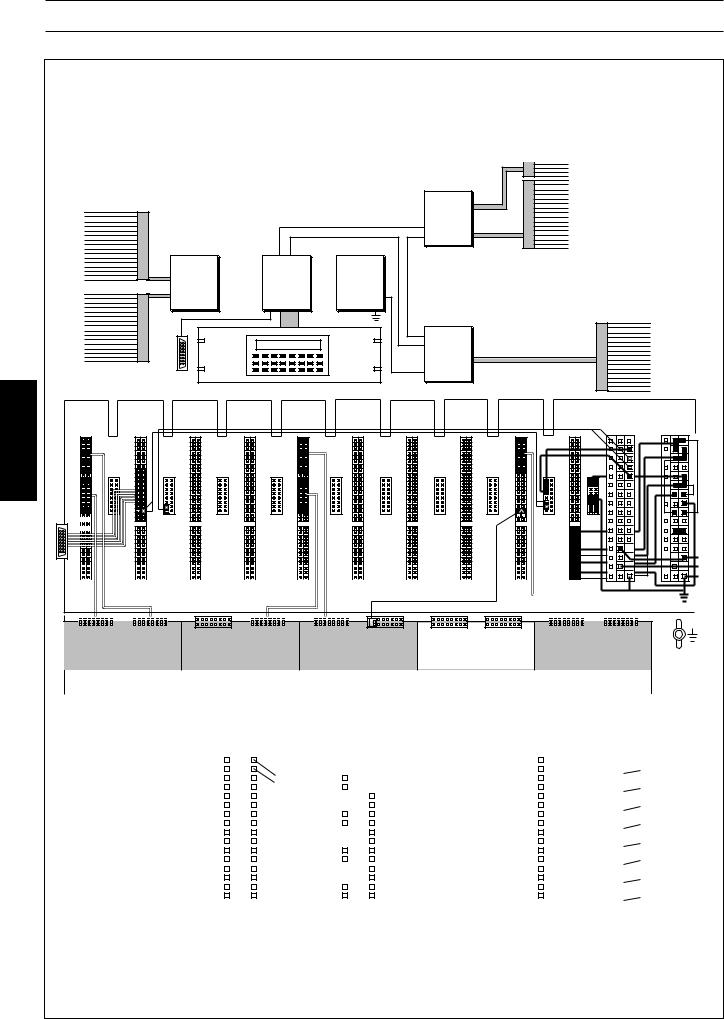
1.GENERAL INTRODUCTION
|
|
|
|
|
1 |
|
|
SM40 SURVEILLANCE CENTRE |
|
|
|
(maximum system layout) |
|
|
|
|
|
|
|
|
|
|
|
|
|
|
|
|
|
|
|
|
|
|
2

1.GENERAL INTRODUCTION
1.1 |
Introduction to the SM40 Surveillance Centre |
|
|
In large public address distribution systems, which often play a key role in alarm and evacuation |
1 |
|
installations, it is vital that the correct functioning of the large number of amplifiers and loudspeakers used |
|
|
can be verified. |
The SM40 Surveillance Centre is designed to monitor the status of amplifiers, loudspeakers, and cabling in large PA systems. Because it pinpoints any failures in the system, it saves a great deal of time, minimising repair costs as well as ensuring that the system is fully functional at the earliest possible moment.
On detection of a malfunction, error messages are generated automatically, giving the precise time and location of the fault. These messages can either be relayed to the system’s LCD display, or sent to an external printer for a permanent hard-copy record of the malfunctions. The messages can also be linked to warning lamps, buzzers, or personal paging units, alerting security and maintenance personnel.
The possibility also exists to automatically switch in a spare amplifier in place of an amplifier which becomes faulty.
A pilot tone signal is generated which is inserted into the Test inputs of Philips SQ45 power amplifier range. The Surveillance Centre is able to scan for the presence of this signal in up to 4096 monitoring devices, located in strategic places (at amplifier outputs, loudspeaker cabling junction boxes, inside loudspeaker enclosures) throughout a PA distribution system. It can also receive ‘internal error’ information from an SM40 Routing System itself, as well as responding to external sensing devices such as smoke detectors and micro switches.
Being controlled by a microprocessor, the system is particularly flexible, specific functions being easily programmed and changed to allow for alterations in the PA system configuration and surveillance requirements.
Because the system is built around 19-inch rack mounted Euro Card circuit boards, expansion or alterations to the system are quickly and easily carried out.
A total Surveillance Centre would comprise:
-19-inch rack unit, containing a microprocessor controlled SM40 Surveillance Centre
-100V loudspeaker line, and low voltage loudspeaker, monitoring devices; external warning devices (lamps, buzzers, etc.)
-printer, or computer/printer combination.
All SM40 Surveillance Centre internal wiring is particularly installer friendly due to the ‘Quick Fit’ connectors used.
Standard twisted two core screened microphone cable is used to carry data and 15V power between the system and the interlinked Amplifier/Loudspeaker Surveillance Boards.
All SM40 Surveillance Centres are built around the LBB 1370 Basic (starter) System, which is able to sequentially scan 8 Test Lines, each containing up to 128 monitoring devices; receive error input from 2 external sources, activates several relay error sets and synchronises the real-time clock.
The single 19-inch rack frame, capable of holding 9 circuit cards, has enough room to accomodate the Basic System plus 5 extra cards. Adding these cards expands the system, enabling it to feed more amplifiers with the Pilot Test Tone; scan a greater quantity of Test Lines and/or receives a larger amount of error inputs from external devices. However the system is limited by the number of Termination Boards installed.
When a system’s requirements exceed the space offered in a single rack frame, or extra termination boards are required the SM40 Extension Frame LBB 1360 is available. These frames can be linked together to expand the system.
3

2. UNPACKING AND INSTALLATION
SURVEILLANCE BASIC SYSTEM
LBB 1370
|
|
|
|
|
|
|
|
|
|
|
|
|
|
|
|
|
|
|
|
|
|
|
|
|
|
|
|
|
|
|
|
|
|
|
|
|
|
|
|
|
|
|
|
|
|
|
|
|
|
|
|
|
|
|
|
|
|
|
|
|
|
|
|
|
|
|
|
|
|
|
|
|
|
|
|
|
|
|
|
|
|
|
|
|
|
|
|
|
|
|
2 |
|
|
|
|
|
|
|
|
|
|
|
|
|
TB1 |
|
|
|
|
|
|
|
|
|
|
|
|
|
|
|
|
|
TB3 |
|
|
|
|
|
|
|
|
|
TB4 |
|
|
|
|
|
|
|
|
|
|
TB5 |
|
|
|
|
|
RS 232 |
|||||||||||||||||||||||||||||||
|
|
|
|
|
|
|
|
|
|
|
|
|
|
|
|
|
|
|
|
|
|
|
|
|
|
|
|
|
|
|
|
|
|
|
|
|
|
|
|
|
|
|
|
|
|
|
|
|
|
|
|
|
|
|
|
|
|
|
|
|
|
|
|
|
|
|
|
|
|
|
|
|
|
|
|
|
|
|
|
|
|
|
|
|
|
|
|
|||
|
|
|
|
|
|
|
|
|
|
|
|
|
|
|
|
|
|
|
|
|
|
|
|
|
|
|
|
|
|
|
|
|
|
|
|
|
|
|
|
|
|
|
|
|
|
|
|
|
|
|
|
|
|
|
|
|
|
|
|
|
|
|
|
|
|
|
|
|
|
|
|
|
|
|
|
|
|
|
|
|
|
|
|
|
|
|
|
|
||
|
|
|
|
|
|
|
|
|
|
|
|
|
|
|
|
|
|
|
|
|
|
|
|
|
|
|
|
|
|
|
|
|
|
|
|
|
|
|
|
|
|
|
|
|
|
|
|
|
|
|
|
|
|
|
|
|
|
|
|
|
|
|
|
|
|
|
|
|
|
|
|
|
|
|
|
|
|
|
|
|
|
|
|
|
|
|
|
|
connection |
|
|
|
|
|
|
|
|
|
|
|
|
|
|
|
|
|
|
|
|
|
|
|
|
|
|
|
|
|
|
|
|
|
|
|
|
|
|
|
|
|
|
|
|
|
|
|
|
|
|
|
|
|
|
|
|
|
|
|
|
|
|
|
|
|
|
|
|
|
|
|
|
|
|
|
|
|
|
|
|
|
|
|
|
|
|
|
|
|
|
||
|
|
|
|
|
|
PE 1141 |
|
|
|
|
|
|
|
|
|
|
|
|
|
|
Surveillance Switch Card |
|
|
|
|
|
|
|
|
|
|
|
|
|
|
|
|
|
|
|
|
|
|
|
|
Control Relay Card |
|
|
|
|
|
|
|
|
|
|
|
|
card |
|
|
|
|
|
Card |
|
I/O Board |
|||||||||||||||||||||||
|
|
|
|
|
|
|
|
|
|
|
|
|
|
|
|
|
|
|
PE 1268 |
|
|
|
|
|
|
|
|
|
|
|
|
|
|
|
|
|
|
|
|
|
|
|
|
|
|
|
|
|
|
|
|
|
|
|
|
|
|
|
|
|
|
|
|
|
||||||||||||||||||||||||||
|
|
|
|
|
|
|
|
|
|
|
|
|
|
|
|
|
|
|
|
|
|
|
|
|
|
|
|
|
|
|
|
|
|
|
|
|
|
|
|
|
|
|
|
|
|
|
|
|
|
|
|
|
|
|
|
|
|
|
|
|
|
|
Pilot-tone Generator |
|
||||||||||||||||||||||||||
|
|
|
|
|
|
|
|
|
|
|
|
|
|
|
|
|
|
|
|
|
|
|
|
|
|
|
|
|
|
|
|
|
|
|
|
|
|
|
|
|
|
|
|
|
|
|
|
|
|
|
|
|
|
|
|
|
|
|
Processor |
|
|
|||||||||||||||||||||||||||||
|
|
|
|
|
|
|
|
|
|
|
|
|
|
|
|
|
|
|
|
|
|
|
|
|
|
|
|
|
|
|
|
|
|
|
|
|
|
|
|
|
|
|
|
|
|
|
|
|
|
|
|
|
|
|
|
|
|
|
|
|
|
|
|
|
|
|
||||||||||||||||||||||||
|
|
|
|
|
|
|
|
|
|
|
|
|
|
|
|
|
|
|
|
|
|
|
|
|
|
|
|
|
|
|
|
|
|
|
|
|
|
|
|
|
|
|
|
|
|
|
|
|
|
|
|
|
|
|
|
|
|
|
|
|
|
|
|
|
|
|
|
|
|
|
|
|
|
|
|
|
|
|
|
|
|
|
|
|
|
|||||
|
|
|
|
|
|
|
|
|
|
|
|
|
|
|
|
|
|
|
|
|
|
|
|
|
|
|
|
|
|
|
|
|
|
|
|
|
|
|
|
|
|
|
|
|
|
|
|
|
|
|
|
|
|
|
|
|
|
|
|
|
|
|
|
|
|
|
|
|
|
|
|
|
|
|
|
|
|
|
|
|
|
|
|
|
|
|
|
|
|
|
|
|
|
|
|
|
|
|
|
|
|
|
|
|
|
|
|
|
|
|
|
|
|
|
|
|
|
|
|
|
|
|
|
|
|
|
|
|
|
|
|
|
|
|
|
|
|
|
|
|
|
|
|
|
|
|
|
|
|
|
|
|
|
|
|
|
|
|
|
|
|
|
|
|
|
|
|
|
|
|
|
|
|
|
|
|
|
|
|
|
|
|
|
|
|
|
|
|
|
|
|
|
|
|
|
|
|
|
|
|
|
|
|
|
|
|
|
|
|
|
|
|
|
|
|
|
|
|
|
|
|
|
|
|
|
|
|
|
|
|
|
|
|
|
|
|
|
|
|
|
|
|
|
|
|
|
|
|
|
|
|
|
|
|
|
|
|
|
|
|
|
|
|
|
|
|
|
|
|
|
|
|
|
|
|
|
|
|
|
|
|
|
|
|
|
|
|
|
|
|
|
|
|
|
|
|
|
|
|
|
|
|
|
|
|
|
|
|
|
|
|
|
|
|
|
|
|
|
|
|
|
|
|
|
|
|
|
|
|
|
|
|
|
|
|
|
|
|
|
|
|
|
|
|
|
|
|
|
|
|
|
|
|
|
|
|
|
|
|
|
|
|
|
|
|
|
|
|
|
|
|
|
|
|
|
|
|
|
|
|
|
|
|
|
|
|
|
|
|
|
|
|
|
|
|
|
|
|
|
|
|
|
|
|
|
|
|
|
|
|
|
|
|
|
|
|
|
|
|
|
|
|
|
|
|
|
|
|
|
|
|
|
|
|
|
|
|
|
|
|
|
|
|
|
|
|
|
|
|
|
|
|
|
|
FRONT TOP VIEW
INTERCONNECTION BOARDS
PGC CPC |
CRC |
SSC |
1268/10 |
1141/52 |
|
|
1 |
1 |
1 |
1 |
1 |
1 |
1 |
1 |
1 |
1 |
8 |
8 |
8 |
8 |
8 |
8 |
8 |
8 |
8 |
8 |
10 |
10 |
10 |
10 |
10 |
10 |
10 |
10 |
10 |
10 |
17 |
17 |
17 |
17 |
17 |
17 |
17 |
17 |
17 |
17 |
21 |
21 |
21 |
21 |
21 |
21 |
21 |
21 |
21 |
21 |
25 |
25 |
25 |
25 |
25 |
25 |
25 |
25 |
25 |
25 |
30 |
|
30 |
|
30 |
|
|
30 |
|
30 |
|
|
30 |
|
30 |
|
30 |
|
|
30 |
|
|
30 |
|
|
|
|
|
|
|
|
|
|
||||||||||||
|
|
|
|
|
|
|
|
|
|
|
|
|
|
|
|
|
|
|
|
|
|
|
||||||||||||||||||||||
|
|
|
|
|
|
|
|
|
|
|
|
|
|
|
|
|
|
|
|
|
|
|
|
|
|
|
|
|
|
|
|
|
|
|
|
|
|
|
|
|
|
|
|
|
|
b a |
|
|
|
|
|
|
|
|
|
|
|
U-1 |
|
|
|
|
|
|
|
|
|
|
|
|
|
|
|
|
|
|
|
|
|
|
|
|
|
|
|
|
|
||
|
|
|
|
|
|
|
|
|
|
|
|
|
|
|
|
|
|
|
|
|
|
|
|
|
|
|
|
|
|
|
|
|
|
|
|
|
|
|
|
|
|
|
|
|
|
|
|
|
|
|
|
|
|
|
|
|
|
|
|
|
|
|
|
|
|
|
|
|
|
|
|
|
|
|
|
|
|
|
|
|
|
|
|
|
|
|
|
|
|
|
|
|
|
|
|
|
|
|
|
|
|
|
|
|
|
|
|
|
|
|
|
|
|
|
|
|
|
|
|
|
|
|
|
|
|
|
|
|
|
|
|
|
|
|
TEST SIGNALS |
4 |
ERROR |
ERROR |
2 |
TEST LINES |
|
OUTPUT INPUT |
||||||
|
|
|
|
|||
|
|
|
|
|
||
|
|
TERMINATION BOARDS |
|
|
||
|
|
(REAR VIEW) |
|
|
||
4

2. UNPACKING AND INSTALLATION
2.1SM40 Surveillance Centre - Unpacking and installation
In order to ensure that your SM40 Surveillance Centre functions properly, please follow these few simple instructions after unpacking your unit.
1Carefully check the enclosed system components for physical damage caused during shipping. Any complaints should be made immediately to the shipping company.
2Mount the Basic System frame in the appropriate position in the 19-inch rack unit (not higher than shoulder height, so that the display and keyboard can be clearly seen).
3Extension Frames are available to expand the Basic System into a larger system. These should now
|
be mounted, and wired according to the appropriate wiring diagrams. |
2 |
4 |
Mount the amplifiers and auxiliary equipment in the rack(s). |
|
|
If power amplifiers are mounted beneath SM40 frames, a heat shield should be installed above |
|
|
them to deflect hot air currents. |
|
5 |
Taking care to avoid earth (ground) loops, wire the mains power to the units. The SM40 |
|
|
Surveillance Centre will operate successfully on mains voltages from 175 V to 264 V when tapped |
|
|
for 220 V, and from 90 V to 140 V when tapped for 110 V. Be sure to check that your system is |
|
|
wired for the correct mains voltage. |
|
|
Caution: When tapping the system for the correct mains voltage, refer to the documentation |
|
|
supplied with the SM40 system. |
|
|
NOTE: Because it is possible to touch the mains voltage terminals when the frame back panels are |
|
|
opened, it is advisable not to turn the power on at this stage. |
|
6 |
Open the back panel of the Basic system, and check that all of the connectors on the |
|
|
Interconnection Board and Termination boards are firmly in place. If, in the unlikely event that one |
|
|
of the connectors has become disconnected, refer to the enclosed basic system wiring diagram. |
|
7 |
Refering to Termination Board illustrations in chapter 10, wire the Test Lines, Amplifier Test |
|
|
Inputs, and Error Inputs/Outputs, to the screwblock connectors. If a printer or computer is to be |
|
|
used with the system, it should be wired to the RS232 serial interface socket at this time |
|
8 |
Plug the screwblock connectors into the termination boards, ensuring that they are in the correct |
|
|
locations. |
|
9 |
Open the front panel of the rack frame and gently push each of the circuit cards to make sure that |
|
|
they are all firmly connected to the Interconnection Board. |
|
10 |
If, after double checking that all of the mains power and signal wiring is correct, and that the |
|
|
system is adequately earthed, switch on the mains power to the rack. |
|
5
3. SM 40 BASIC SYSTEM AND EXTENSION FRAME
SURVEILLANCE BASIC SYSTEM |
|
|
||
|
|
LBB 1370 |
|
|
|
|
Error |
5 |
Printer error |
|
|
indication |
4 |
System error |
|
|
CRC |
||
16 |
|
3 |
External error |
|
|
U-1 |
2 |
LSB/ASB error |
|
|
|
|||
|
|
|
1 |
General error |
PGC |
CPC |
PE |
|
|
9 |
|
15V |
|
|
TB |
|
|
|
|
8 |
|
|
|
|
|
SSC |
Communication & |
To |
|
1 |
1 |
8x128 |
||
Power supply |
||||
RS232 |
1-8 |
LSBs |
||
|
|
3 |
PGC |
CPC |
|
|
CRC |
|
|
|
SSC |
1268/10 |
1141/52 |
|
|
|
|
|
|
|
|||||
1 |
1 |
1 |
1 |
1 |
1 |
1 |
1 |
1 |
1 |
|
8 |
8 |
8 |
8 |
8 |
8 |
8 |
8 |
8 |
8 |
10 |
10 |
10 |
10 |
10 |
10 |
10 |
10 |
10 |
10 |
|
17 |
17 |
17 |
17 |
17 |
17 |
17 |
17 |
17 |
17 |
RS232 |
21 |
21 |
21 |
21 |
21 |
21 |
21 |
21 |
21 |
21 |
25 |
25 |
25 |
25 |
25 |
25 |
25 |
25 |
25 |
25 |
30 |
|
30 |
|
30 |
|
|
30 |
|
|
30 |
|
|
30 |
|
30 |
|
30 |
|
|
|
30 |
|
|
|
30 |
|
|
|
|
|
|
|
|
|
|
||||||||||||||
|
|
|
|
|
|
|
|
|
|
|
|
|
|
|
|
|
|
|
|
|
|
|
|
|
|
|
|
|
|
|
|
|
|
|
|
|
|
|
|
|
|
|
|
|
|
|
|
|
|
|
|
b a |
|
|
|
|
|
|
|
|
|
|
U-1 |
|
|
|
|
|
|
|
|
|
|
L-2 |
|
L-1 |
|
|
|
|
|
|
|
||||||||||||||||
|
|
|
|
|
|
|
|
|
|
|
|
|
|
|
|
|
|
|
|
|
|
|
|
|
|
|
|
|
|
|
|
|
|
|
|
|
|
|
|
|
|
|
|
|
|
|
|||
|
|
|
|
|
|
|
|
|
|
|
|
|
|
|
|
|
|
|
|
|
|
|
|
|
|
|
|
|
|
|
|
|
|
|
|
|
|
|
|
|
|
|
|
|
|
|
|
|
|
TEST SIGNALS |
|
|
|
ERROR |
ERROR |
|
ERROR |
|
|
|
|
|
TEST LINES |
|
||||||||||||||||||||||||||||||||||||
|
|
|
OUTPUT |
OUTPUT INPUT |
|
|
|
|
|
|
||||||||||||||||||||||||||||||||||||||||
|
|
|
|
|
|
|
|
|
|
|
|
|
|
|
|
|
|
|
|
|
|
|
|
|
|
|
|
|
|
|
|
|||||||||||||||||||
|
|
|
|
|
|
|
|
|
|
|
|
|
|
|
|
|
|
|
|
|
|
|
|
|
|
|
|
|
|
|
|
|
|
|
|
|
|
|
|
|
|
|
|
|
|
|
|
|
||
|
|
|
|
|
|
|
|
|
|
INTERCONNECTION BOARD WIRING AS VIEWED FROM REAR OF RACK UNIT |
|
|
|
|
|
|
||||||||||||||||||||||||||||||||||
|
|
|
|
|
|
|
|
|
|
|
|
|
|
|
|
|||||||||||||||||||||||||||||||||||
|
|
|
|
|
|
|
|
|
|
|
|
|
|
ERROR OUTPUT |
|
ERROR |
|
|
|
|
|
|
|
|
|
|
|
|
|
|
|
|
|
|
||||||||||||||||
TEST SIGNALS |
|
|
|
|
INPUT |
TEST LINES |
|
|||||||||||||||||||||||||||||||||||||||||||
9 |
|
|
|
|
|
|
|
|
|
1 |
|
|
|
|
|
|
|
General |
|
|
|
|
|
|
|
|
|
|
1 Clock sync. |
|
|
|
|
|
|
|
|
|
1 |
|
|
|
|
|
|
|
|
|||
|
|
|
|
|
|
|
|
|
|
|
|
|
|
|
|
|
|
|
|
|
|
|
|
|
|
|
|
|
|
|
|
|
|
|
|
|
|
|
|
|||||||||||
|
|
|
|
|
|
|
|
|
|
|
|
|
|
|
|
|
|
|
|
|
|
|
|
|
2 |
|
|
|
|
|
|
|
|
|
|
|
|
|
|
|
|
|
|
|||||||
10 |
|
|
|
|
|
|
|
|
|
2 |
|
|
|
|
|
|
|
Printer |
|
|
|
|
|
|
|
|
3 |
|
|
|
|
|
|
|
|
|
|
2 |
|
|
|
|
|
|
|
|
||||
|
|
|
|
|
|
|
|
|
|
|
|
|
|
|
|
|
|
|
|
|
|
|
|
|
|
|
|
|
|
|
|
|
|
|
|
|
|
|
|
|
|
|||||||||
11 |
|
|
|
|
|
|
|
|
|
3 |
|
|
|
|
|
|
|
ASB/LSB |
|
|
|
|
|
|
|
|
|
|
|
|
|
|
|
|
|
|
|
|
|
|
3 |
|
|
|
|
|
|
|
|
|
|
|
|
|
|
|
|
|
|
|
|
|
|
|
|
|
|
|
|
|
|
|
|
|
|
|
|
|
|
|
|
|
|
|
|
|
|
|
|
|
|
|
|
|
|
|
|||||
|
|
|
|
|
|
|
|
|
|
|
|
|
|
|
|
|
|
|
|
|
|
|
|
|
|
|
|
|
|
|
|
|
|
|
|
|
|
|
|
|
|
|
|
|
|
|||||
12 |
|
|
|
|
|
|
|
|
|
4 |
|
|
|
|
|
|
|
|
|
|
|
|
|
|
|
|
|
|
|
|
|
|
|
|
|
|
|
|
|
|
|
4 |
|
|
|
|
|
|
|
|
|
|
|
|
|
|
|
|
|
|
|
|
|
|
|
|
|
|
|
|
|
|
|
|
|
|
|
|
|
|
|
|
|
|
|
|
|
|
|
|
|
|
|
|
|
|
|
|
|||
|
|
|
|
|
|
|
|
|
|
|
|
|
|
|
|
|
|
|
|
|
|
|
|
|
|
|
|
|
|
|
|
|
|
|
|
|
|
|
|
|
|
|
|
|
|
|
|
|||
13 |
|
|
|
|
|
|
|
|
|
5 |
|
|
|
|
|
|
|
External |
|
|
|
|
|
|
|
|
|
|
|
|
|
|
|
|
|
|
|
|
|
|
5 |
|
|
|
|
|
|
|
|
|
|
|
|
|
|
|
|
|
|
|
|
|
|
|
|
|
|
|
|
|
|
|
|
|
|
|
|
|
|
|
|
|
|
|
|
|
|
|
|
|
|
|
|
|
|
|
|||||
|
|
|
|
|
|
|
|
|
|
|
|
|
|
|
|
|
|
|
|
|
|
|
|
|
|
|
|
|
|
|
|
|
|
|
|
|
|
|
|
|
|
|
|
|
|
|||||
14 |
|
|
|
|
|
|
|
|
|
6 |
|
|
|
|
|
|
|
|
|
|
|
|
|
|
|
|
|
|
|
|
|
|
|
|
|
|
|
|
|
|
|
6 |
|
|
|
|
|
|
|
|
|
|
|
|
|
|
|
|
|
|
|
|
|
|
|
|
|
|
|
|
|
|
|
|
|
|
|
|
|
|
|
|
|
|
|
|
|
|
|
|
|
|
|
|
|
|
|
|
|||
15 |
|
|
|
|
|
|
|
|
|
7 |
|
|
|
|
|
|
|
System |
|
|
|
|
|
|
|
|
|
|
|
|
|
|
|
|
|
|
|
|
|
|
7 |
|
|
|
|
|
|
|
|
|
|
|
|
|
|
|
|
|
|
|
|
|
|
|
|
|
|
|
|
|
|
|
|
|
|
|
|
|
|
|
|
|
|
|
|
|
|
|
|
|
|
|
|
|
|
|
|||||
|
|
|
|
|
|
|
|
|
|
|
|
|
|
|
|
|
|
|
|
|
|
|
|
|
|
|
|
|
|
|
|
|
|
|
|
|
|
|
|
|
|
|
|
|
|
|||||
16 |
|
|
|
|
|
|
|
|
|
8 |
|
|
|
|
|
|
|
|
|
|
|
|
|
|
|
|
|
|
|
|
|
|
|
|
|
|
|
|
|
|
|
8 |
|
|
|
|
|
|
|
|
|
|
|
|
|
|
|
|
|
|
|
|
|
|
|
|
|
|
|
|
|
|
|
|
|
|
|
|
|
|
|
|
|
|
|
|
|
|
|
|
|
|
|
|
|
|
|
|
|||
|
|
|
|
|
|
|
|
|
|
|
|
|
|
|
|
|
|
|
|
|
|
|
|
|
|
|
|
|
|
|
|
|
|
|
|
|
|
|
|
|
|
|
|
|
|
|
|
|||
|
|
|
|
|
|
|
|
|
|
|
|
|
|
|
|
|
|
|
|
|
|
|
|
|
|
|
|
|||||||||||||||||||||||
|
|
|
|
|
|
|
|
|
|
|
|
|
|
|
|
|
|
|
|
|
|
|
|
|
|
|
|
|
|
|
|
|
|
|
|
|
|
|
|
|
|
|
|
|
|
|
|
|
|
|
|
|
|
|
|
|
|
|
|
|
|
|
|
|
|
|
|
|
|
|
|
|
|
|
|
|
|
|
|
|
|
|
|
|
|
|
|
|
|
|
|
|
|
|
|
|
|
|
|
|
|
|
|
|
|
|
|
|
|
|
|
|
|
|
|
|
|
|
|
|
|
|
|
|
|
|
|
|
|
|
|
|
|
|
|
|
|
|
|
|
|
|
|
|
|
|
|
|
|
|
|
|
|
|
|
|
|
|
|
|
|
|
|
|
|
|
|
|
|
|
|
|
|
|
|
|
|
|
|
|
|
|
|
|
|
|
|
|
|
|
|
|
|
|
|
|
|
|
|
|
|
|
|
TERMINATION BOARD WIRING AS VIEWED FROM REAR OF RACK UNIT
6

3. SM 40 SURVEILLANCE BASIC SYSTEM
3.1 SM40 Surveillance Basic System |
LBB 1370 |
Self contained, fully operational system, around which all SM40 Surveillance Centres are built.
Comprises 4 circuit cards, mounted in a single 19-inch rack frame.
The Surveillance Basic (starter) System is the heart of the SM40 Surveillance Centre. When supplemented with a variety of Euro-cards and PCB’s, a wide range of system configurations are possible, and many different application needs are succesfully met.
Containing, in its single rack frame, the Display and Keyboard, and the Central Processor Card (CPC); (along with its other circuit cards) the Basic System is a self contained, fully working unit in its own right.
Being supplied with one Surveillance Switch Card (SSC) the system is able to sequentially scan 8 seperate test lines, each having upto 128 Amplifier Surveillance Boards (ASB’s) and/or Loudspeaker Surveillance Boards (LSB’s) connected.
The +15V required to power each test line in turn is provided by the in-built PE 1268/10 power supply.unit.
The Basic System is also able to display error information generated by 2 external sources and clock synchronisation using a single contact.
The communication PCB can send information generated by the CPC, via its RS232 port, to a printer or a computer for the production of detailed hard copy of all monitored errors. The control relay card may be 3 used to activate external warning devices (lamps, buzzers, etc.) when an error occurs.
When a centre’s requirement exceed the facilities available in the Surveillance Basic System, further circuit cards (plus the extension frames LBB 1360 necessary to accomodate them) are ordered, expanding the system to meet specific application needs.
Because the Surveillance Basic system is supplied fully wired, adjusted, tested, and mounted in its own 19-inch rack unit, ready for use, it is an ideal model from which to build a larger system.
Units included with Basic System LBB 1370: |
Optional Euro-Cards: |
|
||||
1x |
|
Single 19-inch Rack Frame |
|
CRC |
Control Relay Card |
LBB 1356 |
1x |
|
Power Supply +15V/-15V/+5V |
PE 1141/52 |
SSC |
Surveillance Switch Card |
LBB 1374 |
1x |
|
Power Supply +15V |
PE 1268/10 |
PGC |
Pilot Tone Generator Card |
LBB 1369 |
1x |
IB |
Interconnection Board |
|
TB |
Termination Board |
LBB 1377 |
4x |
TB |
Termination Boards |
LBB 1377/00 |
|
|
|
1x |
CPC |
Central Processor Card + I/0 + |
|
|
|
|
|
|
Surveillance System Software |
|
Optional PCB’s: |
|
|
1x |
CRC |
Control Relay Card |
LBB 1356/00 |
|
|
|
1x |
SSC |
Surveillance Switch Card |
LBB 1374/00 |
Loudspeaker Surveillance Board |
LBB 1367 |
|
1x |
PGC |
Pilot Tone Generator Card |
LBB 1369/00 |
Amplifier Surveillance Board |
LBB 1368 |
|
|
|
|
|
|
|
|
7

3. SM 40 BASIC SYSTEM AND EXTENSION FRAME
SURVEILLANCE BASIC SYSTEM LBB 1370
Plus 1 EXTENSION FRAME LBB 1360
INTERCONNECTION BOARD WIRING AS VIEWED FROM REAR OF RACK UNIT
PGC CPC PGC |
CRC SSC SSC SSC SSC |
PE 1268/10 PE 1141/52 |
|
1 |
1 |
1 |
1 |
1 |
1 |
1 |
1 |
1 |
1 |
8 |
8 |
8 |
8 |
8 |
8 |
8 |
8 |
8 |
8 |
10 |
10 |
10 |
10 |
10 |
10 |
10 |
10 |
10 |
10 |
17 |
17 |
17 |
17 |
17 |
17 |
17 |
17 |
17 |
17 |
21 |
21 |
21 |
21 |
21 |
21 |
21 |
21 |
21 |
21 |
25 |
25 |
25 |
25 |
25 |
25 |
25 |
25 |
25 |
25 |
30 |
|
30 |
|
30 |
|
|
30 |
|
|
30 |
|
|
30 |
|
30 |
|
30 |
|
|
30 |
|
|
30 |
|
|
|
|
|
|
|
|
|
|
||||||||||||
|
|
|
|
|
|
|
|
|
|
|
|
|
|
|
|
|
|
|
|
|
|
|
|
||||||||||||||||||||||
|
|
|
|
|
|
|
|
|
|
|
|
|
|
|
|
|
|
|
|
|
|
|
|
|
|
|
|
|
|
|
|
|
|
|
|
|
|
|
|
|
|
|
|
|
|
|
b a |
|
|
|
|
|
|
|
|
|
|
|
|
U-1 |
|
|
|
|
|
|
|
|
|
|
|
|
|
|
|
|
|
|
|
|
|
|
|
|
|
|
|
|
|
||
|
|
|
|
|
|
|
|
|
|
|
|
|
|
|
|
|
|
|
|
|
|
|
|
|
|
|
|
|
|
|
|
|
|
|
|
|
|
|
|
|
|
|
|
|
|
|
|
|
|
|
|
|
|
|
|
|
|
|
|
|
|
|
|
|
|
|
|
|
|
|
|
|
|
|
|
|
|
|
|
|
|
|
|
|
|
|
|
|
|
|
|
|
|
|
|
|
|
|
|
|
|
|
|
|
|
|
|
|
|
|
|
|
|
|
|
|
|
|
|
|
|
|
|
|
|
|
|
|
|
|
|
|
|
|
|
|
|
|
|
|
|
|
|
|
|
|
|
|
|
|
|
|
|
|
|
|
|
|
|
|
|
|
|
|
|
|
|
|
|
|
|
|
|
|
|
|
|
|
|
|
|
|
|
3 |
TEST SIGNALS |
TEST SIGNALS ERROR |
ERROR |
TEST LINES |
TEST LINES |
|
|
|
|
|
||||||||
|
|
|
|
|
||||||||||||||
|
|
|
|
|
||||||||||||||
|
|
|
|
|
||||||||||||||
25 - 32 |
17 - 24 |
9 - 16 |
1 - 8 |
OUTPUT INPUT |
25 - 32 |
17 - 24 |
9 - 16 |
|
1 - 8 |
|
|
|
|
|
|
|||
|
|
|
|
|
|
|
|
|
||||||||||
|
|
|
|
|
|
|
|
|
|
|
|
LBB 1360 |
||||||
|
PGC |
|
|
PGC |
PGC |
CRC |
CRC |
CRC |
CRC |
|||||||||
|
|
|
||||||||||||||||
|
|
|
|
|
|
|
|
|
|
|||||||||
1 |
1 |
1 |
1 |
1 |
1 |
1 |
1 |
1 |
1 |
8 |
8 |
8 |
8 |
8 |
8 |
8 |
8 |
8 |
8 |
10 |
10 |
10 |
10 |
10 |
10 |
10 |
10 |
10 |
10 |
17 |
17 |
17 |
17 |
17 |
17 |
17 |
17 |
17 |
17 |
20 |
20 |
21 |
21 |
21 |
21 |
21 |
21 |
21 |
21 |
|
|
24 
25 |
|
25 |
|
25 |
|
25 |
|
25 |
|
25 |
|
25 |
|
25 |
|
25 |
|
|
|
|
|
|
|
|
|
|
|||||||||
|
|
|
|
|
|
|
|
|
|
|
|
|
|
|
|
|
|
30 |
30 |
30 |
30 |
30 |
30 |
30 |
30 |
30 |
30 |
+ |
ba |
L-4 |
L-3 |
L-2 |
L-1 |
|
|
|
|
|
|
|
|
|
|
|
|
|
|
|
|
|
|
|
|
|
|
|
|
|
|
|
|
|
|
|
|
|
|
|
|
|
|
|
|
|
|
|
|
|
|
|
|
|
|
|
|
|
|
|
TEST SIGNALS |
TEST SIGNALS |
TEST SIGNALS |
ERROR OUTPUT |
ERROR OUTPUT |
|||||||||||||||||||
73 - 80 |
65 - 72 |
57 - 64 |
49 - 56 |
41 - 48 |
33 - 40 |
25 - 32 |
17 - 24 |
9 - 16 |
1 - 8 |
|||||||||||||||
|
|
|
|
|
|
|
|
|
|
|
|
|
|
|
|
|
|
|
|
|
|
|
|
|
SIDE VIEW FRAMES
Basic frame
Front |
Rear |
Extension frame
8
3. SM 40 BASIC SYSTEM AND EXTENSION FRAME
3.2 Extension Frame |
LBB 1360 |
Single 19-inch rack frame, capable of holding 10 SM40 circuit cards. Complete with power supply, and one Interconnection and Termination Board.
A single rack frame, capable of holding, and interconnecting 10 SM40 circuit cards, has enough room to accomodate the Basic (starter) System, described elsewhere, plus additional Pilot-tone generator cards, Control Relay Cards and Surveillance Switch Cards.
When the number of terminations boards required in an SM40 system exceeds the amount of space offered in this single rack frame, Extension Frame LBB 1360, is available.
Units included with Extension Frame LBB 1360:
1x |
|
Single 19-inch rack frame |
|
1x |
|
Power Supply Unit +15V/ -15V |
PE1113/50 |
1x |
IB |
Interconnection Boards |
|
1x |
TB |
Termination Boards |
LBB 1377/00 |
These components, mounted in the 19-inch rack frame, are supplied tested, and wired to accept and power
up to 10 SM40 circuit cards. |
3 |
|
SM40 EXTENSION FRAME
LBB 1360
TB1 |
PE 1113 |
FRONT TOP VIEW
9

3. SM 40 BASIC SYSTEM AND EXTENSION FRAME
|
SURVEILLANCE |
|
|
|
|
|
|
|
|
||
|
BASIC FRAME |
|
|
|
|
|
|
|
|
|
|
|
|
+15V supply & comm |
|
Pilot-tone |
|
Error |
|
|
|
||
|
|
1 |
8 |
1 |
16 |
1 |
2 |
3 |
4 |
5 |
|
|
|
|
SSC |
|
PGC |
|
CRC |
|
RS232 |
||
|
|
|
|
|
CPC |
||||||
|
|
|
|
|
|
|
|
|
|
|
I/O |
|
|
|
|
|
|
|
|
|
|
|
2 |
|
|
|
|
|
|
|
|
|
|
|
IC |
|
|
|
|
|
|
|
|
|
|
|
supply |
3 |
PE1141/50 |
PE1268/10 |
|
|
|
|
|
|
|
|
|
Supply for |
|
Supply for |
|
|
|
|
|
|
|
|
|
eurocards |
surveillance boards |
|
|
|
|
|
|
|
|
||
|
|
220 V |
|
|
|
|
|
|
|
|
|
|
|
|
|
|
|
|
|
|
|
|
DATA BUS |
|
|
|
|
|
|
|
|
|
|
|
ADDRESS BUS |
|
|
|
|
|
|
|
|
|
|
|
CONTROL BUS |
|
DISPLAY |
MICRO- |
32K |
|
32K |
|
2 |
|
|
I/O BOARD |
RS232 |
|
|
|
IC |
|
|
|
|||||
|
BUFFER |
PROCESSOR |
EPROM |
|
RAM |
INTERFACE |
|
|
|
||
|
|
Z80 B |
|
|
|
|
|
|
|
|
|
|
X-tal. |
|
REAL-TIME |
|
X-tal. |
|
|
|
|
|
Clock data 2 |
|
5.068 MHz |
|
CLOCK |
|
32.768 KHz |
|
|
|
|
|
|
|
|
|
|
|
|
|
|
|
|
|
Clock data 3 |
|
|
|
|
|
|
|
DATA |
|
|
|
|
|
|
|
|
|
|
CLOCK |
|
|
Clock data 4 |
||
|
|
|
|
|
|
serial/buffers |
|
|
|||
|
|
|
|
|
|
|
|
|
|
|
Clock data 5 |
|
|
|
|
|
|
|
|
|
|
|
Clock data 6 |
|
CENTRAL PROCESSOR CARD |
|
|
|
|
|
|
||||
|
|
|
|
|
Clock data 1 |
|
|
|
Communication |
||
|
|
|
|
|
|
|
2 |
|
|
Comm. |
|
|
|
|
|
|
|
|
I C |
|
|
|
|
|
10 |
|
|
|
|
|
|
|
|
|
|

4. OPERATING AND PROGRAMMING THE SM40 SURVEILLANCE CENTRE
4.1 |
Central Processor Card - CPC |
|
|
Eurocard 10 x 22 cm with an ‘a b’ connector (2 x 32). A microprocessor which can scan over 4000 |
|
|
monitoring devices, and activate more than 100 relays, via the communication line. |
|
|
At the heart of the SM40 Surveillance Centre is the Central Processor Card (CPC). Capable of sequentially |
|
|
scanning 4096 monitoring devices; activating 64 SSC solid state relays, and 40 CRC relay sets; and sending |
|
|
error information to a display, external computer, or printer; this is a powerful piece of equipment. It |
|
|
provides a system of this type with a great amount of possibilities. |
|
|
A Display & Keyboard mounted in the rack unit’s front panel, is used to display the scanning status and any |
|
|
detected errors, and also to carry out the user programming. |
|
|
When programming is complete the CPC returns to its normal scanning mode and, until a secret password |
|
|
is entered, the keyboard has no influence on the processor. |
|
|
The basic functions of the Central Processor Card are as follows: |
|
|
SCANNING of Amplifier Surveillance Boards (ASB’s) and/or Loudspeaker Surveillance Boards (LSB’s). |
|
|
This is done by sequentially sending 15V power to each of the 8 Test Lines of the Surveillance Switch Cards |
|
|
(SSC’s) in turn, then sending communications data to each board in each line sequentially. |
|
|
Translating the error data received from the ASB’s and LSB’s, along with external sensing devices, and |
|
|
relaying this information to the display, or via the RS232 port, to a printer or external computer. |
|
|
ACTIVATING of relays, to switch on external warning devices (lamps, buzzers, paging units, etc.) via |
|
|
Control Relay Cards (CRC’s). |
|
|
CHECKING of system hardware. The processor acts as a “watchdog”, continuously patrolling the SM40 |
|
|
Surveillance Centre hardware to check for errors, malfunctions or disconnections. If a problem exists, |
|
|
information, stating which card is faulty, is relayed to the display or printer. |
|
|
An automatic restore function is also incorporated, so that when an internal error occurs, the system will not |
4 |
|
hang-up, and when an error is rectified no manual system reset is required. |
|
|
REAL TIME CLOCK is built into the unit, and (in the program’s ‘Enable Print’ mode) is displayed on the |
LCD, giving date, hours and minutes. When an error occurs, the current time and date are transmitted to the printer. Synchronisation is via A17 on Surveillance Switch Cards No.1.
SERIAL INTERFACE. The standard RS232 serial interface connector mounted on a bracket on the frame, and wired to the CPC, allows the system to communicate with a wide variety of personal, mini, and mainframe computers as well as direct to serial printers.
The communication has 8 data bits, and the baud-rate is selectable between 300, 1200, 2400, 4800 and 9600 baud.
This, and the other I/O port parameters, such as number of Stop Bits, and Parity can be set in the installer programming menu.
SM40’s standard default parameters are:
2400 baud, 8 data bits, 1 stop bit, even parity.
A yellow LED, mounted on the front edge of the card indicates that the CPC is in communication with the rest of the SM40 Surveillance Centre, and 1 green LED indicates that adequate supply voltage is present.
The CPC has additional driver stages for the communication lines of 5 of the Extension Frames used to expand the Surveillance Basic System.
11
4. OPERATING AND PROGRAMMING THE SM40 SURVEILLANCE CENTRE
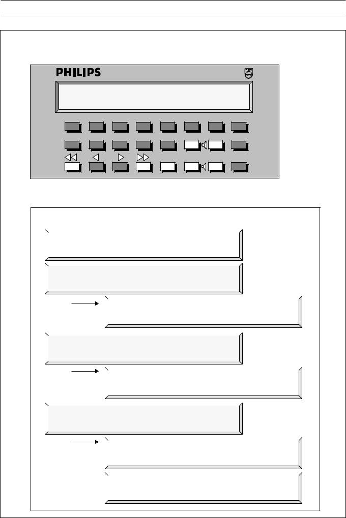
DISPLAY & KEYBOARD
* * * SM40 SURVEILLANCE SYSTEM * * * |
|||||||
DAY:XX-XX |
|
|
|
|
TIME:XX:XX |
||
0 |
1 |
2 |
3 |
4 |
A |
B |
C |
5 |
6 |
7 |
8 |
9 |
1 |
0 |
Break |
|
|
|
|
Mute |
1 |
0 |
Enter |
Grey shaded keys are functional in the programming mode. i.e
USER MENU, INSTALLER MENU & SERVICE MENU
DISPLAY READOUTS AFTER ENTERING 'USER-MENU' PASSWORD (9, 6, ENTER)
|
|
|
|
|
|
|
|
|
|
|
|
|
|
>WELCOME TO SURVEILLANCE PROGRAMMING< |
|
|
|
||||
|
|
|
>> VERSION 1.21 |
DATE: XX-XX-XX << |
|
|
|
|||
|
|
|
|
|
|
|
|
|
|
|
|
|
|
|
|
|
|
|
|
|
|
|
|
|
|
|
|
|
|
|||
|
|
|
|
|
|
|
|
|
|
|
|
|
|
*USER MENU* |
|
|
Scroll with 'ENTER' |
|
|
||
|
|
|
PRESS '1' TO SELECT ERROR PRINTING |
|
|
|
|
|||
4 |
|
|
|
|
|
|
|
|
|
|
|
|
|
|
|
|
|
|
|
|
|
1 |
|
|
|
|
|
|
|
|||
|
|
|
|
|
|
|
||||
|
DIPSLAY OF ERRORS ON PRINTER |
|
||||||||
|
|
|
|
|
||||||
|
|
|
|
PRESS '0' TO DISABLE; '1' TO ENABLE: _ |
|
|||||
|
|
|
|
|
|
|
|
|
|
|
|
|
|
|
|
|
|
|
|
|
|
|
|
|
|
|
|
|
|
|
|
|
|
|
|
|
|
|
|
|
|
|
|
|
|
|
*USER MENU* |
|
|
Scroll with 'ENTER' |
|
|
||
|
|
|
PRESS '2' TO PRINT CURRENT ERRORS |
|
|
|
|
|||
|
|
|
|
|
|
|
|
|
|
|
|
|
|
|
|
|
|
|
|
|
|
|
2 |
|
|
|
|
|
|
|
||
|
|
|
|
|
|
|
|
|||
|
|
*USER MENU* |
Scroll with 'ENTER' |
|
||||||
|
|
|
|
|
||||||
|
|
|
|
|
PRINTER NOT READY; PLEASE CHECK |
|
||||
|
|
|
|
|
|
|
|
|||
|
|
|
|
|
|
|
|
|
|
|
|
|
|
|
|
|
|
||||
|
|
|
|
|
|
|
|
|
|
|
|
|
|
*USER MENU* |
|
|
Scroll with 'ENTER' |
|
|
||
|
|
|
PRESS '3' TO SET REAL-TIME CLOCK |
|
|
|
|
|||
|
|
|
|
|
|
|
|
|
|
|
|
|
|
|
|
|
|
|
|
|
|
|
3 |
|
|
|
|
|
|
|
||
|
|
|
|
|
|
|
|
|||
|
|
ENTER |
DD-MM-HH:MM |
|
||||||
|
|
|
|
|
|
|||||
|
|
|
|
|
|
XX-XX XX:XX |
|
|||
|
|
|
|
|
|
|
||||
|
|
|
|
|
|
|
|
|
|
|
|
|
|
|
|
|
|||||
|
|
|
|
|
|
|||||
|
|
|
|
|
ENTER LAST 2 DIGITS OF CURRENT YEAR: XX |
|
||||
|
|
|
|
|
|
|
|
|
|
|
|
|
|
|
|
|
|
|
|
|
|
12

4. OPERATING AND PROGRAMMING THE SM40 SURVEILLANCE CENTRE
4.2Display and Keyboard
A programming tool, containing a keyboard for user key assignment and a display which shows the sequence of programming. Mounted in the front panel of the rack unit.
Users of the SM40 Surveillance Centre are able to program and make changes to the functions of their system, quickly and easily, with the aid of the Display And Keyboard. This is a simple programming tool comprising a 24 key keyboard and a 2x40 character lcd display which shows the sequence of programming.
SM40 KEY FUNCTIONS
0-9 |
Numeric keys to type-in password; select |
|
programs and functions; and to insert the |
|
time and date in the User Programming |
|
menu. |
|
Moves the cursor 1 position to the right |
|
when setting the real-time clock in the User |
|
Programming menu. |
|
Moves the cursor 1 position to the left when |
|
setting the real-time clock in the User |
|
Programming menu. |
|
Non-functional |
|
Non-functional |
1 |
Non-functional |
0 |
Non-functional |
1 |
Non-functional |
0 |
Non-functional |
Mute |
Non-functional |
ANon-functional
BNon-functional
CNon-functional
Break |
In most cases this key will abort a command |
|
|
|
and return the user to the main menu for the |
|
|
|
next programming sequence without any new |
|
|
|
information being stored. When in the main |
|
|
|
menu, pressing will return the system to the |
|
|
|
normal scan mode. |
|
|
Enter |
Enters numerical inputs into the memory and |
|
|
|
moves to the next program stage, or at the |
|
|
|
end of a program sequence; to the main |
|
|
|
menu ready for the next program. |
|
|
When programming is completed, the system returns to its |
|
|
|
normal scanning mode and, until the correct password is |
|
|
|
|
|||
entered, the keyboard has no influence on the processor, |
|
4 |
|
thus guarding the system from unauthorized tampering. |
|
||
The unit is mounted in the rack units’ front panel, which |
|
||
may be flipped up, locking automatically in a horizontal |
|
|
|
position. This is an ideal angle from which to view and |
|
|
|
operate the unit. |
|
|
|
|
|
|
|
13

4. OPERATING AND PROGRAMMING THE SM40 SURVEILLANCE CENTRE
4.2.1Display readout
During the remainder of this chapter, specific contexts (status) and user actions are shown in the left column, and possible display results are shown in the right column. Characters between quotes (e.g. ‘Key’) denote keyboard inputs, and occurrances of XX and YY in any displays shown in the right column denote information which is dependant on the system configuration, or entered by the user.
|
When the SM40 system is powered up, either one of the following two displays is shown: |
|
|
|
|
||
Status / Action |
|
Result / Remarks |
|
|
|
|
|
|
|
|
|
|
|
|
|
When memory was cleared the display shows: |
|
|
|
|
|
|
|
|
|
|
|
|
|
||
|
* * * SYSTEM MUST BE PROGRAMMED * |
* * |
|
|
|||
|
|
|
|
|
|||
|
|
|
* * * GO TO INSTALLER MENU |
* |
* * |
|
|
|
|
|
|
|
|
|
|
|
|
|
|
|
|
|
|
When the system was installed previously, the display shows:
This message will disappear after 2-seconds, and the system will start scanning.
|
|
|
|
|
* * * SM40 |
SURVEILLANCE SYSTEM * * * |
|
|
DATE:XX-XX |
TIME:XX:XX |
|
|
|
|
|
|
|
|
|
When scanning and error printing are enabled (refer to User Programming Menu) the display shows:
The second display line is used to display the current date and time.
SCANNING ZONE: XX UNIT XX |
|
DATE: XX-XX |
TIME: XX:XX |
When scanning and error printing are disabled (refer to User Programming Menu) the display shows:
The second display line is used to display errors. Errors are indicated one by one in a
4 continuous cycle.
Loudspeaker/amplifier errors are displayed as follows:
External errors are displayed as follows:
System errors are displayed as follows:
SCANNING ZONE: XX UNIT: XXX
SCANNING ZONE: XX UNIT: XXX ERROR IN ZONE: XX UNIT: XXX
SCANNING ZONE: XX UNIT: XXX <ERROR> EXTERNAL INPUT: XX
SCANNING ZONE: XX UNIT: XXX <ERROR> SWITCH CARD: XX
SCANNING ZONE: XX UNIT: XXX <ERROR> RELAY CARD: I-XX
SCANNING ZONE: XX UNIT: XXX <ERROR> RELAY CARD: II-XX
14
 Loading...