


 Loading...
IntelliVue MP2/5/20/30/40/50/60/70/80/90/MP5T/X2
CONFIGURATION GUIDE
IntelliVue Patient Monitor
MP2/5/20/30/40/50/60/70/80/90
MP5T/X2
For monitor release G.0 with software revision G.0x.xx
Patient Monitoring

Philips Medizin Systeme Boeblingen GmbH
Hewlett-Packard Str. 2
71034 Boeblingen
Germany
© Copyright 2002-2008
Koninklijke Philips Electronics N.V.
All Rights Reserved
Part Number M8000-9306M
Reorder Number: 4535 641 12621
Printed in Germany 10/08

Table Of Contents
1 Understanding Configuration |
1 |
Who is this Guide for? |
1 |
Which Monitor Models is this Guide for? |
1 |
What is Configuration Mode? |
2 |
Who Can Change the Monitor Configuration? |
2 |
Understanding Profiles and Settings |
3 |
Entering and Leaving Configuration Mode |
6 |
About the IntelliVue Support Tool |
6 |
2 Configuring Profiles and Settings Blocks |
9 |
|
|
Getting Started |
9 |
Modifying an Existing Profile |
10 |
Modifying an Existing Settings Block |
11 |
Creating New Profiles |
11 |
Deleting a Settings Block or Profile |
13 |
Renaming a Settings Block or Profile |
13 |
Changing the Monitor’s Default Profile |
13 |
Unlocking a Settings Block or Profile |
13 |
Configuring a Second / Third Main Display |
14 |
3 Configuring Screens |
17 |
|
|
Understanding Screen Settings |
17 |
Modifying an Existing Screen |
18 |
Creating New Screens |
18 |
Configuring Screens on an XDS Remote Display |
18 |
Changing the Content of Screen Elements |
19 |
Changing the Size and Position of Screen Elements |
21 |
Configuring SmartKeys |
21 |
Configuring Special Screen Settings |
22 |
4 Configuration Settings Appendix |
25 |
|
|
About Configuration Settings |
25 |
Profile Settings |
28 |
Measurement Settings |
29 |
Monitor Settings |
84 |
Unique Monitor Settings |
118 |
Global Settings |
147 |
Hardware Settings |
176 |
Monitor Database Configuration |
184 |
H Option-Specific Settings |
187 |
Release-Specific Information |
188 |
1

5 Screen & Profile Overview |
191 |
About the Screen Configurations |
191 |
Sample Screen Image (.bmp) |
193 |
MP60/MP70/MP80/MP90 Configuration Overview |
194 |
MP40/MP50 Configuration Overview |
198 |
MP20/MP30 Configuration Overview |
202 |
MP20 Junior & MP20L Configuration Overview |
206 |
MP5 Configuration Overview |
208 |
MP5T Configuration Overview |
213 |
MP2/X2 Configuration Overview |
214 |
Screen Overview |
215 |
MP60/MP70/MP80/MP90 Screen Overview |
216 |
MP40/MP50 Screen Overview |
225 |
MP20/MP30 Screen Overview |
230 |
MP20 Junior (M20) & MP20L (M21) Screen Overview |
235 |
MP5 Screen Overview |
236 |
MP5 Options B10/B11/B14 Screen Overview |
241 |
MP5T Screen Overview |
242 |
MP2 Screen Overview |
243 |
X2 Screen Overview |
244 |
2
1
Understanding Configuration
Who is this Guide for?
This book is for anyone making permanent changes to the configuration of an IntelliVue Patient Monitor. You must understand English, be familiar with the monitor and its Instructions for Use, know how to make changes to measurements and settings in monitoring mode, and understand the clinical implications of any changes you make.
WARNING Before starting monitoring, check that the configuration meets your requirements, especially patient category, alarm limits and paced setting.
WARNING Changing the configuration may alter the way the monitor performs when monitoring patients. Do not change anything unless you are aware of the possible consequences, especially if you are monitoring a patient whilst in configuration mode.
Which Monitor Models is this Guide for?
The descriptions and configuration settings in this configuration guide are valid for IntelliVue Patient Monitors MP2, MP5, MP20/30, MP40/50, MP60/70, MP80/90, and the IntelliVue X2 MultiMeasurement Module (when used as a standalone monitor), release G.0 with software G.0x.xx. This guide can not be used for other monitor models or IntelliVue monitors with other software releases.
Not all information contained in this guide applies to all monitor models. If a certain section applies only to certain models, this is indicated next to the section heading.
For example, if a certain section does not apply to the MP2 and X2, or - in other words - only applies to monitor models MP5, MP20/30, MP40/50, MP60/70, and MP80/90, it would be indicated like this:
MP5-90 <Section Heading>
only
1
1 Understanding Configuration |
What is Configuration Mode? |
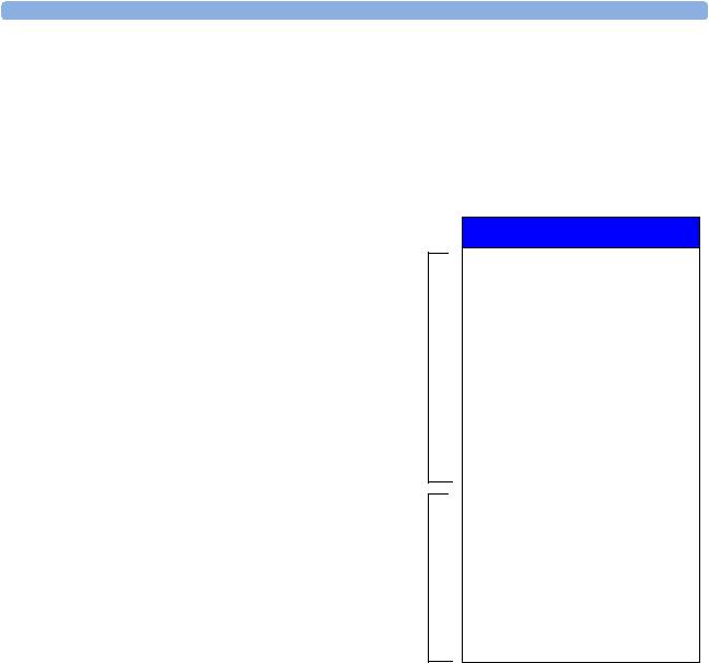
What is Configuration Mode?
The monitor ships with preset configurations that are suitable for common monitoring situations. To develop and store your own configurations you must switch to the monitors configuration mode. Configuration mode is a password-protected operating mode that lets expert users make permanent changes to the monitor configuration. It is an extension of monitoring mode; it contains all of the settings available in monitoring mode plus some settings that are accessible only in configuration mode.
For example, when you access the Setup SpO2 menu in monitoring mode, you will only be able to see and change these settings. 
In configuration mode, these additional settings become visible. 
Setup SpO2
High Limit |
: |
100 |
|
Low Limit |
: |
90 |
|
Desat Limit |
: |
80 |
|
Alarms |
: |
On |
|
SpO2 |
: |
On |
|
Pulse (Sp02) |
|
|
|
Label |
: |
SpO2 |
|
Set Perf Ref. |
|
|
|
QRS Volume |
: |
1 |
|
Tone Modulation |
: |
Yes |
|
Tone Mod. Type |
: |
Enhanced |
|
Perfusion |
: |
On |
|
Average |
: |
10 |
sec |
High Alarm Delay |
: |
10 |
sec |
Low Alarm Delay |
: |
10 |
sec |
Desat Delay |
: |
20 |
sec |
NBP Alarm Suppr. |
: |
On |
|
Extd. Auto OnOff |
: |
Disabled |
|
Color |
: |
Cyan |
|
|
|
|
|
In monitoring mode, you can change settings, but cannot permanently store the changes to the monitor configuration.In configuration mode, you can change and permanently store settings to the monitor configuration.
Who Can Change the Monitor Configuration?
Only people authorized to do so by their institution should make changes in configuration mode. They require the configuration mode password.
2

Understanding Profiles and Settings |
1 Understanding Configuration |
Understanding Profiles and Settings
The IntelliVue patient monitor is highly configurable. To manage its various settings, settings are grouped into six main categories:
•Profiles
•Screens
•Monitor settings
•Measurement settings
•Global settings
•Hardware settings
All settings except hardware settings can be changed in configuration mode. Hardware settings can be changed in service mode only (with some exceptions).
Profiles
Profiles are named combinations of the following “building blocks”:
• |
Patient category |
|
|
|
|
Profiles |
|||||
• |
Paced status |
||||
|
|
|
|||
• |
(Display) Screen |
Profile |
: |
Profile Adult |
|
|
|
|
|||
• |
Measurement Settings block |
Patient Category |
: |
Adult |
|
|
|
|
|||
• |
Monitor Settings block. |
Paced |
: |
Yes |
|
|
|
|
|||
A monitor can have up to 20 different Profiles. |
Display |
: |
6 Waves A |
||
When you load a Profile, the configured combination |
Measmnt. Settings |
: |
Measmt. Adult |
||
of building blocks becomes active. |
Monitor Settings |
: |
Monitor A |
||
This provides a powerful method to easily adapt the |
|||||
monitor to specific clinical scenarios or users, or |
|
|
|
||
switch back and forth between different configurations depending on specific phases within a case.
Consider this example: You are in the ER. Your monitor is configured for an adult patient. Your next patient is a 5-year old child. By switching to a predefined pediatric ER Profile, you can have appropriate measurement settings (such as alarm limits), patient category and so forth very easily, instead of having to alter measurements and limits individually. In this example, your monitor’s Profiles can be based on the age and condition of your patient, but there are of course other use models.
3

1 Understanding Configuration |
Understanding Profiles and Settings |
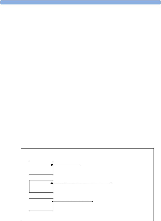
This graphic illustrates the concept of Profiles and their building blocks in the IntelliVue Patient Monitor.
Notice that settings blocks and screens are only linked to a Profile. This indicates that storing a changed Profile saves the combination of building blocks, but not individual monitor settings, measurement settings, or Screens. Changes that you have made to measurement or monitor settings, or screens can only be stored in the appropriate type of settings block or Screen. For details, see "Modifying an Existing Settings Block" on page 11.
Patient Category
For each profile, a patient category is defined. This patient category becomes active when you load the Profile. It determines
–the algorithm the monitor uses to process and calculate some measurements (for example arrhythmia),
–the safety limits that apply for some measurements (for example NBP), and
–the alarm limit ranges for all measurements.
Note that a change of the patient category does not change any alarm limits to fit this category.
Paced
For each profile, the paced status is defined. The defined paced status becomes active when you load the Profile. The paced setting determines whether the monitor shows pacemaker pulses or not. When Paced is set to No, pace pulses are filtered and therefore do not show in the ECG wave. For paced patients, Paced must be set to Yes.
4

Understanding Profiles and Settings |
1 Understanding Configuration |
Display Screens
A Screen defines the overall selection, size and position of measurement waves, numerics and SmartKeys on the monitor display. A monitor can have a maximum of 20 preconfigured Screens, optimized for common monitoring scenarios. Examples of different Screens include the Big Numerics, the 12lead ECG, and the Horizon Screen. For a complete list of Screens supplied with your monitor model, see the section "Screen Overview" on page 215.
For each Profile, a Screen is defined. This Screen becomes the active Screen when you load the Profile. If you are using two or three main displays, for each main display a different Screen can be configured.
Measurement Settings
Measurement settings are settings specific to each measurement, for example alarm limits, measurement color, or measurement unit. For a complete list of measurement settings, see the section "Measurement Settings" on page 29.
A monitor can have a maximum of 10 blocks of measurement settings. Each block includes the complete list of measurement settings available. You can configure individual measurement settings differently for each settings block. By configuring different settings blocks, you can provide customized combinations of measurement settings for different profiles.
A typical example are the measurement settings blocks provided in the factory default configurations (documented in this guide). The measurement settings blocks Measmt. Adult, and Measmt. Pedi, for example, differ mainly by the alarm limits which are configured differently for different patient ages. When you switch to a different Profile, for example from Profile Adult to Profile Pedi, the measurement settings block defined for that Profile becomes active.
Monitor Settings
Monitor settings define general aspects of how the monitor works, and include settings that affect more than one measurement, such as alarm volume, report settings, or display brightness. For a complete list of monitor settings, see the section "Monitor Settings" on page 84.
A monitor can have a maximum of 10 blocks of monitor settings. Each block includes the complete list of monitor settings available. You can configure individual monitor settings differently for each settings block. By configuring different settings blocks, you can provide customized combinations of monitor settings for different profiles.
For example, you could generate a monitor settings block, in which the monitor’s display brightness is lowered and the alarm volume is softened, and call it “Night”. When you then assign this block to a new Profile and name it accordingly, for example “Profile Night”, you can easily switch between day and night settings.
Global Settings
Global settings are typically set once at monitor installation by service personnel and include settings such as Altitude, Line Frequency, or Label Set. Global settings are not part of a Profile. They can be changed in configuration mode only and are automatically stored in the monitor’s configuration with each change. For a complete list of Global Settings, see the section "Global Settings" on page 147.
Hardware Settings
Most hardware settings can only be changed in service mode. They are typically set once at monitor installation by service personnel, and include settings, such as Keyboard layout, the configuration of the monitor interfaces, or video settings, such as Display Type, Display Size, and Display
5

1 Understanding Configuration |
Entering and Leaving Configuration Mode |
Resolution. Like global settings, hardware settings are independent of Profiles, and any changes you make to the hardware settings configuration are automatically stored, there is no need to save them in an extra step. For a complete list of Hardware Settings, see the section "Hardware Settings" on page 176, or refer to the Service Guide of your monitor model, provided on the Documentation DVD supplied with your monitor.
Entering and Leaving Configuration Mode
Switching between monitoring and configuration mode does not affect the active settings. You can even continue to monitor patients while in configuration mode. The password for configuration mode is given in the monitor’s service documentation.
To enter configuration mode:
1 In the Main Setup menu, select Operating Modes.
2 Select Config and enter the password.
The monitor displays Config at the right hand side of the status line and in the center of the Screen while you are in configuration mode.
Before you leave configuration mode, always be sure to store any changes you made. You must store changes made to each Settings Block and to each Profile, individually. As it may be difficult to remember whether the settings you changed belong to a Monitor Settings block or a Measurement Settings block, we recommend that you store each block before you leave configuration mode.
WARNING If you are handing over the monitor to the end-users directly after configuration, make sure that it is in Monitoring mode.
To leave configuration mode either:
♦In the Main Setup menu, select Operating Modes and then select the operating mode you require or
♦Switch the monitor off, then switch it on again.
–If you switch the monitor off and then on again after less than one minute, it returns in monitoring mode with the same settings (“hotstart”).
–If you leave the monitor switched off for more than one minute, the Profiles and settings loaded when you switch back on are determined by the Automat. Default setting. See “Global Settings” on page 147.
About the IntelliVue Support Tool
The IntelliVue Support Tool is a PC-based software application that is designed to help configuring IntelliVue monitors and to manage IntelliVue Monitor configurations.
Using the Support Tool, you can, for example, read in (clone) a configuration from an IntelliVue monitor to a PC, modify this configuration offline on the PC, and then store (clone) the changed version back to the monitor. With the Support Tool you can clone configurations to more than one monitor at a time.
You can also use the Support Tool to make backups of your configurations, or generate configuration reports. The configuration files generated by the Support Tool are stored in a format that can be e-mailed.
6
About the IntelliVue Support Tool |
1 Understanding Configuration |
What Can I Configure with the Support Tool?
You can configure everything you can configure on the monitor, except that you cannot change individual monitor and measurement settings.
In addition to the configuration on the monitor, the Support Tool allows, for example:
•Changing the order of items in the lists of Screens, measurement or monitor settings blocks.
•Unlocking Profiles, Screens and settings blocks.
•Making realtime waves, or screen trends overlap on the Screen.
•Importing Screens into a configuration, and copying Screens between configurations.
•Importing SmartKey configurations into a configuration.
•Copying monitor settings, measurement settings, and global settings between config files.
•Importing, creating and modifying drug calculator configurations.
For a complete description of the Support Tool functionality, refer to the Support Tool Instructions for Use, provided with the Support Tool.
How Can I Get a Support Tool License Key?
To use the Support Tool, you must have a license key. To get a license key, you must complete a special training. Please contact your local Philips Customer Response Center for further details.
The Support Tool functionality your license key permits you to use, depends on your function (e.g. Biomed / CE / Configuration Expert) and your level of training.
License keys are issued to individuals and they may not be shared. The Support Tool tracks the use of each license key: you will be held responsible for any configuration changes made using your license key.
7

1 Understanding Configuration |
About the IntelliVue Support Tool |
8

2
Configuring Profiles and
Settings Blocks
Getting Started
To start configuring your monitor, access Profiles by selecting either:
•the Profiles screen element from the monitor’s Info Line, or
•the Profiles SmartKey  , or
, or
•Profiles from the Main Setup menu.
The configuration pop-up keys will appear to let you carry out configuration tasks.
Using the Configuration Pop-up Keys
In configuration mode, the pop-up keys allow you to:
activate a Profile or settings block
create a new Profile or |
rename the selected |
settings block based on the |
Profile or settings block |
current one |
|
|
make the current Profile |
save active settings into the selected |
the default Profile |
delete the selected |
|
settings block, or settings blocks |
Profile or settings block |
into the selected Profile. |
|
Select the Confirm pop-up key to apply your changes.
9
2 Configuring Profiles and Settings Blocks |
Modifying an Existing Profile |
Modifying an Existing Profile
You can change the settings within an existing Profile. The monitor remembers any changes made when you switch between monitoring mode and configuration mode. All changes can be permanently stored in configuration mode, as described in the following sections.
Be aware that if you don’t store changes they will be reset to the monitor’s stored configuration when you
•change from configuration or monitoring mode to service or demonstration mode,
•load Profiles or Settings Blocks, or
•switch off the monitor for more than one minute (if the Global Setting Automat. Default is set to Yes).
Changing the Combination of Settings Blocks in an Existing Profile
To permanently save a different combination of settings blocks into an existing Profile:
1Select the Profile you want to change and select the Load pop-up key to activate it.
2Change the patient category and paced status if necessary.
3Load the settings blocks you want to have into the activated Profile one after the other by selecting them in the Profiles menu and then selecting the Load pop-up key. These settings become active immediately in the monitor, but the asterisk beside the Profile name in the Profiles menu shows that the newly loaded blocks are not yet stored as part of the Profile.
4Select the Profile again.
5Select the Store pop-up key.
This example shows the changing of a Profile. The existing Profile 1 was built from a combination of Screen A + Monitor Settings Block A + Measurement Settings Block A.
The new Profile 2 is built from a combination of Screen B + Monitor Settings Block D + Measurement Settings Block C. This is now the active Profile, because it is loaded into the monitor’s active memory.
Active settings
Display screens
Monitor settings
Measurement  settings
|
|
|
|
|
|
Settings blocks |
|
|
|
|
|
|
Examples |
|||||
|
|
|
|
|
|
|
|
|
|
|
|
|
|
|
|
|
|
screens |
|
|
|
|
|
|
|
|
|
|
|
|
|
|
|
|
|
|
|
load |
|
|
|
|
|
|
|
|
|
|
|
|
|
|
|
|
|
layout |
|
|
A |
|
|
B |
|
|
C |
|
|
D |
|
E |
content |
||||
|
|
|
|
|
|
|
|
|
|
|||||||||
|
|
|
|
|
|
|
|
|
|
|
|
|
|
|
|
|
|
alarm volume |
|
|
|
|
|
|
|
|
|
|
|
|
|
|
|
|
|
|
|
|
|
|
|
|
|
|
|
|
|
|
|
|
|
|
|
|
|
|
load |
|
|
|
|
|
|
|
|
|
|
|
|
|
|
|
|
|
alarms latching |
|
|
|
|
|
|
|
|
|
|
|
|
|
|
|
|
|
alarm off time |
|
|
|
A |
|
|
B |
|
|
C |
|
|
D |
|
E |
QRS volume |
||||
|
|
|
|
|
|
|
|
|
Network setting |
|||||||||
load |
|
|
|
|
|
|
|
|
|
|
|
|
|
|
|
|
|
ECG alarm limits |
|
|
|
|
|
|
|
|
|
|
|
|
|
|
|
|
|
||
|
|
|
|
|
|
|
|
|
|
|
|
|
|
|
|
|
||
|
|
|
|
|
|
|
|
|
|
|
|
|
|
|
|
|
||
|
|
|
|
|
|
|
|
|
|
|
|
|
|
|
|
|
ABP alarms on/off |
|
|
|
A |
|
|
B |
|
|
C |
|
|
D |
|
E |
NBP repeat time |
||||
|
|
|
|
|
|
|
|
|
Resp trigger mode |
|||||||||
|
|
|
|
|
|
|
|
|
|
|
|
|
|
|
|
|
|
|
|
|
|
|
Existing Profile 1 |
|
|
New Profile 2 |
|
|
|||||||||
|
|
|
|
|
|
|
|
|||||||||||
10
Modifying an Existing Settings Block |
2 Configuring Profiles and Settings Blocks |
Modifying an Existing Settings Block
To change settings in an existing settings block:
1Select the settings block you want to change and select the Load pop-up key to activate it.
2Make the changes to the individual measurements or monitor settings.
3Select the Store pop-up key to overwrite the existing settings. Changes to a settings block affect all Profiles in which this block is used.
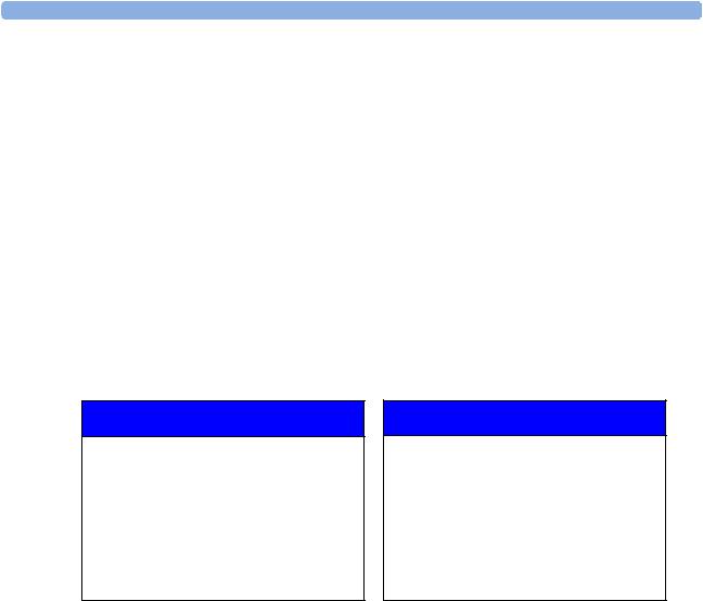
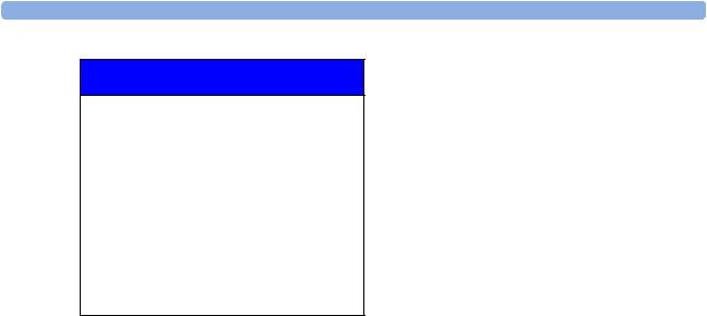
Creating New Profiles
Follow these steps to create a new Profile ICU B based on the Profile ICU A and add it to the list of Profiles stored in the monitor. As creating a Profile requires you to activate different settings, you should not do this while monitoring a patient. Each new name you assign to Profiles or Settings Blocks must be unique, otherwise you have two items with the same name and you will not be able to distinguish them.
Existing Profile: |
Profile to be created: |
Profiles
Profile |
: |
ICU A |
Patient Category |
: |
Adult |
Paced |
: |
No |
|
|
|
Display |
: |
6 Waves A |
Measmnt. Settings |
: |
Measmt. A |
Monitor Settings |
: |
Monitor A |
|
|
|
Profiles
Profile |
: |
ICU B |
Patient Category |
: |
Pedi |
Paced |
: |
No |
|
|
|
Display |
: |
6 Waves B |
Measmnt. Settings |
: |
Measmt. B |
Monitor Settings |
: |
Monitor B |
|
|
|
1Choose a Profile similar to the one you want to create from the list of Profiles available in the monitor. To preview the combination of settings blocks contained in any Profile, in the Profiles menu, select that Profile from the list. The Profiles menu (which is grayed-out) changes to indicate the contents of the selected Profile. To view the settings blocks of the active Profile, select Current.
2Select Load to activate this Profile.
3Create a new Profile that references the same settings as the active Profile:
a.In the Profiles menu, select Profile.
b.Select the pop-up key New.
c.Use the on-screen keyboard to type a meaningful name for the new Profile, in this case ICU B. If you do not name the Profile, the monitor will assign a default name. You can rename the Profile later.
d.Select Enter.
e.Select Load to activate the new Profile.
4Create new settings blocks for the new Profile.
a.In the Profiles menu, select Monitor Settings.
11

2 Configuring Profiles and Settings Blocks |
Creating New Profiles |
b.Select the pop-up key New.
c.Use the on-screen keyboard to type the name of the new settings block, in this case Monitor B. If you do not name the Settings Block, the monitor will assign a default name. You can rename the Settings Block later.
d.Select Enter. You have now created a new settings block containing the same monitor settings as the block Monitor A.
e.Repeat this procedure to create a new measurement settings block.
You have now prepared the structure of the Profile you are creating.
5Select the required Patient Category for the new Profile. In the Profiles menu, select either Adult, Pedi, or Neo, or select As Is to retain the patient category active at the time this Profile is activated. Note that if you configure Patient Category in the default Profile to As Is, the monitor starts after a coldstart with Patient Category set to Neo. A coldstart will be caused, for example, after changing the monitor’s database configuration, see "Monitor Database Configuration" on page 184.
6Select the required Paced mode for the new Profile. In the Profiles menu, select Yes for paced patients, No for non-paced patients, or As Is to retain the paced status active at the time this Profile is activated. Note that if you configure Paced in the default Profile to As Is, the monitor starts after a coldstart with Paced set to Yes. A coldstart will be caused, for example, after changing the monitor’s database configuration, see "Monitor Database Configuration" on page 184.
7Select a Screen for the new Profile.
a.In the Profiles menu, select Display
b.Select the Screen you require from the pop-up list of available Screens.
c.Select Load to confirm your choice.
d.If the monitor has more than one main display, repeat these steps for the additional displays.
NOTE If you are using an XDS Remote Display as second or third main display, the default Screen for this display must be configured in the XDS Application software. It cannot be stored as part of the Profile configuration of the IntelliVue monitor. For more detail, refer to the Installation and Configuration Guide for the XDS Application.
8Adjust monitor and measurement settings as required.
9Store the changed settings to the settings blocks. In the Profiles menu, select
Measmnt. Settings, and then select Store and then Confirm to apply your changes. Repeat this for Monitor Settings. There is no undo function.
10Store the finished Profile. In the Profiles menu, select Profile and then select Store and then Confirm to apply your changes. There is no undo function.
CAUTION When changing settings, you are strongly advised to create new settings blocks, rather than storing changes to the existing ones. Similarly, when changing a Profile, you are strongly advised to create a new Profile, rather than storing changes to an existing one. Once you store changes to a settings block or Profile, there is no way to undo these changes, unless you have saved a backup using the Support Tool. Settings blocks may be used in more than one Profile. If you edit a settings block it will change in the other Profiles in which it is used.
12
Deleting a Settings Block or Profile |
2 Configuring Profiles and Settings Blocks |
Deleting a Settings Block or Profile
You cannot delete a locked settings block, or one that is used in any Profile. You must remove it from the Profile or delete the Profile first.
1From the Profiles menu, select the block or Profile you want to delete.
2Select the Delete pop-up key.
Renaming a Settings Block or Profile
If you rename a settings block that is used in other Profiles, the name changes in the other Profiles too.
1From the Profiles menu, select the block or Profile you want to rename.
2Select Rename.
3Use the on-screen keyboard to type the new name, then select Enter to apply the change.
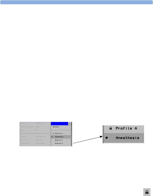
Changing the Monitor’s Default Profile
Every monitor has one default Profile. This is marked with a black diamond.The monitor loads the default Profile:
•when returning to monitoring mode after leaving demonstration Mode (but not after leaving configuration or service mode).
•after discharging a patient.
•after being switched off for more than 60 seconds (only if Automat. Default is set to Yes).
To change the default Profile:
1In the Profiles menu, select the Profile you want to set as default.
2From the pop-up keys select Set Default. The “default diamond” jumps to this Profile to indicate that it is now this monitor’s default Profile. This setting takes effect immediately, you do not have to switch the monitor off and on again.
Unlocking a Settings Block or Profile
Profiles and settings blocks can be locked to prevent them from being modified or deleted. This ensures that a minimum configuration is always available. A locked Profile or settings block is identified (in configuration mode only) by a lock symbol.
You cannot unlock Profiles or settings blocks in the monitor’s configuration mode. To lock or unlock Profiles or settings blocks you need to use the IntelliVue Support Tool.
13
2 Configuring Profiles and Settings Blocks |
Configuring a Second / Third Main Display |
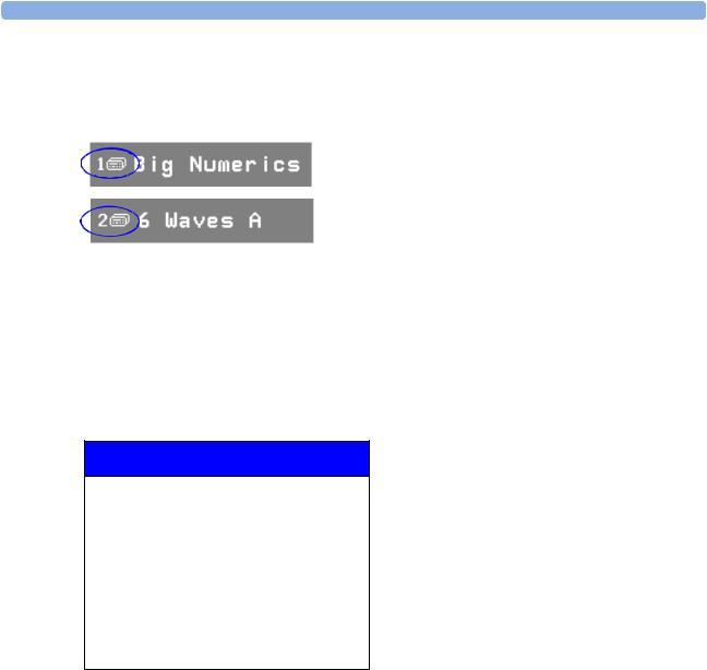
Configuring a Second / Third Main Display
To distinguish between individual main displays, the displays are numbered on the Screen. The number is shown next to the Screen Name field.
A second main display can be used with
•an MP90 with a Dual CPU, or
•an MP2/X2, MP5, MP60/70, MP80, or MP90 with a single CPU, when using an XDS Remote Display as the third display.
Display 1 is always the built-in display or the display connected to the first CPU of the Dual CPU MP90 monitor. Display 2 is the display connected to second CPU of the Dual CPU MP90 monitor or the XDS Remote Display.
Profiles
Profile |
: |
ICU B |
Patient Category |
: |
Adult |
Paced |
: |
Yes |
|
|
|
Display 1 |
: |
6 Waves B |
Display 2 |
: |
12 Lead ECG |
Measmnt. Settings |
: |
Measmt. B |
Monitor Settings |
: |
Monitor B |
|
|
|
A third main display can be used with
•a D80 Intelligent Display connected to a Dual CPU MP90 monitor, or
•an MP90 with a Dual CPU, when using an XDS Remote Display as the third display.
Display 1 is always the display connected to the first CPU of the MP90 monitor. Display 2 is the display connected to second CPU, and Display 3 is the display connected to either the D80 or the XDS Remote Display.
14
Configuring a Second / Third Main Display |
2 Configuring Profiles and Settings Blocks |
Profiles
Profile |
: |
ICU B |
Patient Category |
: |
Adult |
Paced |
: |
Yes |
|
|
|
Display 1 |
: |
6 Waves B |
Display 2 |
: |
12 Lead ECG |
Display 3 |
: |
Big Numerics |
Measmnt. Settings |
: |
Measmt. B |
Monitor Settings |
: |
Monitor B |
|
|
|
Loading a Screen on a Second / Third Display
To load a Screen onto the second or third main display,
•on the second/third display, enter the Change Screen menu and select a Screen from the list of available Screens, or
•on any display, enter the Profiles menu, select Display 2 (or Display 3) and select a Screen from the list of available Screens (not possible on the main display of MP2 and X2 monitors).
NOTE If you are using an IntelliVue monitor with the XDS Remote Display as either the second or third display, the selection of Screens available for the XDS Remote Display can be different from the Screen selection for the other displays.
Changing Elements on a Second / Third Display
To change elements on the second or third main display:
1Load the Screen that you want to modify onto the second/third display.
2Make the required changes to the Screen.
3Store the Screen. To do this, enter the monitor’s configuration mode, select Profiles -> Display 2 (or Display 3), then select the Store pop-up key.
NOTE Any change to a Screen will mark that Screen modified. In the Change Screen menu, the modified Screen is shown linked to the original Screen and marked with an asterisk (*).
If you load the same Screen onto more than one display, then modify them differently, and then store one of the Screens, the modified Screen on the other displays will still be available. The stored Screen will be available on all displays except on the XDS Remote Display.
Changes made to a Screen viewed on an XDS Remote Display will be stored on the PC connected to the XDS Remote Display and will not be part of the monitor configuration, see "Configuring Screens on an XDS Remote Display" on page 18.
15

2 Configuring Profiles and Settings Blocks |
Configuring a Second / Third Main Display |
16
3
Configuring Screens
During monitoring, you can change the content of most of the Screen elements, for example you can exchange a Resp wave for a Pressure wave. These changes can be permanently stored as part of the Screen settings in configuration mode.
You can also use the IntelliVue Support Tool to configure Screens offline on a personal computer and then upload them as part of a configuration file to one or more patient monitors. To use the IntelliVue Support Tool for Screen configuration, you must have a support tool and a support tool license key that entitles you to use the Screen configuration functionality. See "About the IntelliVue Support Tool" on page 6 and the Support Tool Instructions for Use.
Understanding Screen Settings
Screen settings are stored in the Screen. Changing a Screen setting modifies the Screen. This is indicated by an asterisk (*) in front of the Screen name. In the Change Screen menu, modified Screens are shown linked to their parent Screens.
Screen settings include:
•the basic layout of a Screen, i.e. the selection, size, and position of any Screen element visible on the Screen. The Screen layout cannot be modified in the monitor’s configuration mode.
•the content of each Screen element, i.e. the information displayed in each Screen element.
•the selection and sequence of SmartKeys available on a Screen.
•special settings that determine the behavior of certain Screen elements, such as Screen trends, realtime waves, embedded trend windows, or embedded Other Bed Overview windows.
17

3 Configuring Screens |
Modifying an Existing Screen |
Modifying an Existing Screen
To change an existing Screen:
1 Load the Screen and make the changes to the Screen.
2 In configuration mode, select Profiles -> Display (or Display 2, or Display 3).
3In the list of Screens, the modified Screen is shown linked to the original Screen and marked with an asterisk (*). Select the Store pop-up key to overwrite the existing Screen. Changes to the Screen affect all Profiles in which this Screen is used.
NOTE Changes made to a Screen viewed on an XDS Remote Display will be stored on the PC connected to the XDS Remote Display and will not be part of the monitor configuration, see "Configuring Screens on an XDS Remote Display" on page 18.
Creating New Screens
1Load a Screen similar to the one you want to create from the list of Screens available in the monitor.
2Create a new Screen based on the active Screen:
a. In the Profiles menu, select Display (or Display 2, or Display 3).
b.Select the pop-up key New.
c.Use the on-screen keyboard to type a meaningful name for the new Screen. If you do not name the Screen, the monitor will assign a default name. You can rename it later.
d.Select Enter.
3Change the content of the Screen as required.
4Store the finished Screen:
a. In the Profiles menu, select Display (or Display 2, or Display 3).
b.Select the pop-up key Store and then Confirm to apply your changes. There is no undo function.
NOTE Changes made to a Screen viewed on an XDS Remote Display will be stored on the PC connected to the XDS Remote Display and will not be part of the monitor configuration, see "Configuring Screens on an XDS Remote Display" on page 18.
Configuring Screens on an XDS Remote Display
For certain IntelliVue monitor models, the XDS Remote Display (IntelliVue XDS solution) can be used as second or third main display.
When you make changes to a Screen that is viewed on an XDS Remote Display, be aware of the following implications:
•The changes are stored on the XDS Remote Display and not on the monitor.
•The changed Screen is not part of the monitor configuration and can therefore not be cloned to another monitor using the IntelliVue Support Tool.
•The changed Screen can be modified with the Screen Editor of the IntelliVue Support Tool.
18

Changing the Content of Screen Elements |
3 Configuring Screens |
For more details regarding the configuration of the XDS Remote Display, refer to the Installation and Configuration Guide for the XDS Application.
Changing the Content of Screen Elements
Changing the Content of a Wave Element
To change the content of a wave element on a Screen,
1Select the wave you want to change.
2From the wave menu that appears, select Change Wave and then select the wave you want to be displayed.
Changing the Content of a Numeric Element
To change the content of a numeric element on a Screen,
1Select the numeric you want to change. You can only change numerics that are not directly associated with (aligned to) a wave.
2From the Setup menu that appears, select Change Numeric and then select the numeric you want to be displayed.
Changing the Content of a Screen Trend Element
To change the content of a screen trend element on a Screen,
1Select the screen trend you want to change.
2From the trend menu that appears, select Change Trend and then select the screen trend you want to be displayed.
Changing the Content of a High Resolution Trend Element
MP5-90 only
To change the content of a HiRes Trend element on a Screen,
1Select the HiRes Trend you want to change.
2From the menu that appears, select the HiRes trend you want to be displayed.
Depending on the H option (see "Understanding H and M Options" on page 27) and C option of your monitor, the following parameters are available for selection:
|
H10 / H40 |
H20 |
H30 |
Comments |
|
|
|
|
|
|
|
btbHR |
X |
X |
X |
These 4 parameters are included in the OxyCRG option |
|
Any SpO2 |
X |
X |
X |
(C08) |
|
MP5: tcpO2 not available. |
|||||
Resp |
X |
X |
X |
||
tcpO2 |
|
X |
|
|
19

3 Configuring Screens |
Changing the Content of Screen Elements |
|
H10 / H40 |
H20 |
H30 |
Comments |
|
|
|
|
|
Pulse |
X |
X |
X |
MP20 -90 monitors only |
Any Perf |
X |
X |
X |
|
tcpCO2 |
X |
X |
|
|
CO2 |
X |
X |
X |
|
ABP |
X |
X |
X |
|
PAP |
X |
|
X |
|
CVP |
X |
X |
X |
|
ICP |
X |
X |
X |
|
CPP |
X |
X |
X |
|
BIS |
X |
X |
X |
|
CCO |
X |
X |
X |
|
AWP |
X |
X |
X |
|
Any Agent |
|
|
X |
|
Delta SpO2 |
|
X |
|
|
inO2 |
X |
|
X |
|
Displaying Timers on the Main Screen
MP5-90 If you want to have a timer displayed on the Main Screen, you can substitute it for a numeric which is not only directly associated with a wave.
To display a timer on the Main Screen,
1Select the numeric you want to substitute.
2Select Change Numeric.
3Select Any Timer. The monitor automatically uses the timer label with the highest priority that is not displayed on the Screen yet. See "Configuring Timers" on page 139.
Be aware of the following restrictions:
•If limited space is available, some elements displayed in the Timers window may not be displayed. The minimum information displayed is the elapsed or remaining time.
•The maximum number of timers that can be displayed on the Main Screen depends on your monitor model:
–MP60-90: four timers
–MP40-50: three timers
–MP20-30: two timers
–MP5/MP5T: one timer
–MP2/X2: no timer
•Any timer label can only be used once per Screen.
Displaying a Clock on the Main Screen
MP5-90 If you want to have a clock displayed on the Main Screen, you can substitute it for a numeric which is not only directly associated with a wave.
To display a clock on the Main Screen,
20

Changing the Size and Position of Screen Elements |
3 Configuring Screens |
1Select the numeric you want to substitute.
2Select Change Numeric.
3Select Clock.
Be aware of the following restrictions:
•Only one clock can be displayed per Screen
•If limited space is available, the label “Clock” may not be displayed. The minimum information displayed is the time.
Displaying a ProtocolWatch Status Indicator on the Main Screen
MP5-90 If you want to have a ProtocolWatch status indicator displayed on the Main Screen, you can substitute it only for a numeric which is not directly associated with a wave.
To display a ProtocolWatch status indicator on the Main Screen,
1Select the numeric you want to substitute.
2Select Change Numeric.
3Select PW Status.
Only one ProtocolWatch status indicator can be displayed per Screen.
Changing the Size and Position of Screen Elements
You cannot change the size and position of Screen elements. This is a configuration service that is provided, at a charge, by Philips, for monitors with option C20.
Configuring SmartKeys
There are two ways to configure SmartKeys:
•Configuring a different list of SmartKeys for each Screen (not possible for MP2/X2)
•Configuring a global list of SmartKeys that applies for all Screens
Configuring a Different List of SmartKeys for Each Screen
MP5-90 The selection and order of SmartKeys that are specific to a Screen are stored as part of the Screen, i.e. as a only Screen setting. This can be configured on the monitor (in configuration mode) or by using the Support
Tool Screen Editor. The following describes how to configure SmartKeys on the monitor. For a detailed description on how to use the Support Tool Screen Editor, see the Support Tool Instructions for Use.
To change the selection of SmartKeys displayed,
1Select Main Screen, then select the left double arrow key to scroll back one page of SmartKeys.
2Select the SmartKey SmartKeys to open a menu that lists all SmartKeys currently configured for that Screen. From the pop-up key line, select Add to open a second menu that contains all available SmartKeys.
3From the second menu, select the desired SmartKey. This adds the new key to the bottom of the list of configured SmartKeys (on the left). The maximum number of SmartKeys per Screen is 30 for the MP60/70/80/90, and 24 for the MP40/50, MP20/30, and MP5.
21

3 Configuring Screens |
Configuring Special Screen Settings |
To delete a SmartKey from the list of configured SmartKeys,
♦select it in the list, then select the pop-up key Delete.
To move a SmartKey to a different position,
♦Use the Sort Up and Sort Down pop-up keys. The number of SmartKeys visible at a time depends on the monitor’s display resolution:
SVGA: 6
XGA: 7
SXGA: 9
WXGA: 9
WXGA+: 10
WSXGA: 11
Configuring a Global List of SmartKeys for All Screens
The global list of SmartKeys is stored as a unique monitor setting in the monitor configuration. See the section "Configuring User Interface Settings - Keys" on page 143 for details on how to configure the global SmartKey list.
Individual SmartKey configurations for each Screen override the global SmartKey configuration. The global SmartKey list will therefore only be visible when you load a Screen that has no SmartKeys configured to it.
If you want to use the global SmartKeys for all Screens on a monitor, you must delete all individual SmartKeys from all Screens in the configuration.
Configuring Special Screen Settings
Configuring the Wave Channel Speed
To change this setting, select the measurement wave on the Screen to open the related Wave menu.
Change Speed This setting determines the wave speed of the related wave channel.
If set to Global, the speed of the wave channel follows the monitor setting Global Speed (or RespiratorySpeed, or EEG Speed) as described under "Configuring User Interface Settings" on page 110.
If set to any of the fixed speeds (6.25, 12.5, 25, 50 mm/sec), the speed of that wave channel follows its own distinct setting and is not affected by any changes of the Global Speed. The wave channel speed is independent of the wave (label) depicted in the channel. If you change the wave, the new wave will retain the set channel speed.
Configuring Screen Trends
To change the following settings, select the screen trend on the Screen to open the related Trend menu.
Change TrendTime This setting determines in a screen trend. If set to Global, the trend time in the screen trend channel follows the monitor setting Screen Trend Time as described under "Configuring Screen Trend Settings" on page 91. If set to any of the fixed times (30min, 1h, 2h, 4h, 8h, 12h), the screen trend time follows its own distinct time setting and is not affected by any changes of the global Screen Trend Time.
22

Configuring Special Screen Settings |
3 Configuring Screens |
Change View The screen trend presentation can be configured to Tabular, Graphical, Horizon, or Histogram. The Tabular view can only be used with aperiodic measurements, such as NBP, C.O., C.I., PAWP. If you configure the view of an NBP trend, for example, to Tabular, and during monitoring the user changes the trend to a periodic measurement, such as ABP, the view automatically switches to Graphical.
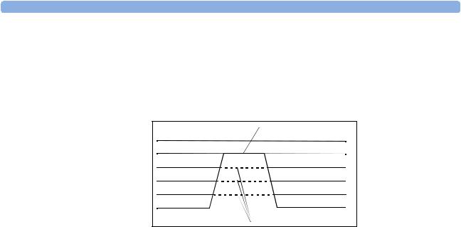
ShowHorizon Trend The horizon view is made up of 4 elements:
1a horizon, drawn in white, as a reference baseline to help you visualize changes in the patient’s condition.
2a graphical trend, displaying patient data for the set TrendTime.
3a trend indicator arrow, indicating how the patient trend has developed in the last ten minutes.
4a deviation bar, showing how the currently measured value deviates from the stored baseline.
If you set ShowHorizon Trend to Yes, all 4 elements of the horizon view are shown. If you set it to No, the graphical trend information (2) is not displayed in the trend channel.
Configuring an Embedded Trend Window
To change the following settings, select the embedded Trend window on the Screen to open the related pop-up key line. Note that the following settings are Screen settings and therefore do not affect the behavior of the normal (not embedded) Vital Signs and Graph Trend windows.
Select Interval This setting defines the trend interval that will be used in the embedded trend window when the corresponding Screen (with the embedded trend window) is opened.
Graph Trend / Vital Signs This setting defines the view (Graphical Trends or Vital Signs table) of the embedded trend window when the corresponding Screen is opened. The view can be changed at any time.
Select Group This setting defines the trend group that is displayed in the embedded trend window when the corresponding Screen is opened.
The following setting applies for embedded Graph Trend windows only. To change the setting, select the embedded Graph Trend window on the Screen, then select one of the segments on the left side of the window to open the segment menu.
No. of Segments This setting defines the number of trend segments displayed in the embedded Graph Trends window when the Screen is opened.
Configuring an Embedded CSA Window
MP40-90 To change the following settings, select the embedded CSA window on the Screen to open the related only pop-up key line. Note that the following settings are Screen settings and therefore do not affect the
behavior of the normal (not embedded) CSA window.
On/Off SEF defines whether the SEF trend line is displayed in the embedded CSA window when the corresponding Screen is loaded.
On/Off MDF defines whether the MDF trend line is displayed in the embedded CSA window when the corresponding Screen is loaded.
On/Off PPF defines whether the PPF trend line is displayed in the embedded CSA window when the corresponding Screen is loaded.
23
3 Configuring Screens |
Configuring Special Screen Settings |
Buffer defines which of the three preconfigured buffers is used when the Screen with the embedded CSA window is loaded.
On/Off Clipping Set Clipping to On to improve the 3-D presentation of the embedded CSA and make it more “readable”. When set to On, peaks in the spectral lines are artificially clipped at a certain height (see "CSA Window Configuration Implications" on page 98). If Clipping is Off, peaks can be displayed over the full window height which may result in a more cluttered presentation.
Clipping |
Hidden lines |
Frequency Scale defines the bandwidth displayed in the embedded CSA.
Configuring an Embedded Other Bed Window
MP5-90 For Screens with an embedded Other Bed window, you can configure which bed is displayed in the Other only Bed window each time the Screen is loaded.
To configure the embedded Other Bed window,
1select the Other Bed window on the Screen
2select the pop-up key My Care Group. This opens the Care Group menu where you can choose between the following settings:
–Bed <xx> (Bed ID)
If you select a specific Bed ID, the monitor displays the associated bed every time the Screen is loaded. If this bed is unavailable, the message “No data from bed” is shown in the embedded window.
–Any Bed
Select Any Bed if you want the monitor to display the first bed shown in the care group list. If this bed is removed from the care group, the new first bed in the care group is automatically displayed. The setting Any Bed might be unavailable if it has been disabled for this Screen using the Support Tool.
–Blank (Factory Default)
This is the factory default setting used on the “Other Bed” Screen that is part of the Support Tool Screen library. If an embedded Other Bed window is configured to Blank, the window is empty when the Screen is loaded.
At any time during monitoring, the user can select the Other Bed window and temporarily change the current setting.
24

4
Configuration Settings
Appendix
About Configuration Settings
The IntelliVue Patient Monitor is pre-configured with factory default settings when it is shipped. This section documents the factory default settings and lists the configuration implications that need to be considered when changing settings from their default.
The configuration implications are only provided in this guide. You must read this document before you modify monitor configurations.
The settings documented here are valid for IntelliVue Patient Monitors release F.0 with software F.0x.xx.
Documenting Monitor Configurations
If you change settings from their default, this document will no longer reflect your configuration.
A Philips representative or trained biomedical engineer can generate a detailed report of the changed monitor configuration using the IntelliVue Support Tool. Make sure you review the description of this functionality in the Support Tool Instructions for Use before you interpret the content of this report.
Understanding Configuration Implications
When you permanently change any element of the configuration, you must consider the effect of the new configuration on both patient and application behavior. For additional information on the context of the configuration settings, see your monitors Instructions for Use. Always ensure that the monitor users are aware of the configuration settings.
Using the Configuration Tables
The “breadcrumb trail” at the top of each table indicates which Settings Block the settings are grouped under. For example, “Measurement Setting: Main Setup -> Measurements -> ECG” means that the ECG settings in the table below the heading are part of the Measurement Settings Block. This is also the path you should follow to access the settings in the table: in this example, to configure ECG settings, in the Main Setup menu, select Measurements and then select ECG.
How to read the configuration tables
The following is a (modified) example of a configuration table, as you will find it in the sections of this manual.
25
4 Configuration Settings Appendix |
About Configuration Settings |
Factory Defaults
Item Name |
Oper. |
|
MP20 - MP90 |
|
MP5 - MP90 |
|
MP20 (M20/M21) |
MP5T |
|
|
MP2/X2 |
|||||
|
Mode |
|
(H10/20/40) |
|
(H30) |
|
|
MP5 (H10/20/40) |
MP5 (B10/B11/B14) |
|
||||||
|
|
|
|
|
|
|
|
|
|
|
||||||
|
|
|
|
|
|
|
|
|
|
MP2/X2 |
|
|
|
|
|
|
|
|
|
|
|
|
|
|
|
|
|
|
|
|
|
|
|
|
C |
M |
|
Profile |
Profile |
Profile |
Profile |
Profile |
Profile |
Profile |
Profile |
Profile |
Profile |
Profile |
Profile |
Profile |
|
|
|
|
Adult |
Pedi |
Neo |
Adult |
Pedi |
Neo |
Adult |
Pedi |
Neo |
Adult |
Pedi |
Neo |
Outdoor |
|
|
|
|
|
|
|
|
|
|
|
|
|
|
|
|
|
Alarms from |
x |
x |
|
Sys. |
|
|
|
|
|
|
|
|
|
|
|
|
|
|
|
|
|
|
|
|
|
|
|
|
|
|
|
|
|
Sys. High |
x |
x |
|
160 |
120 |
90 |
180 |
|
|
|
|
|
|
|
|
160 |
Sys. Low |
x |
x |
|
90 |
70 |
40 |
70 |
|
|
|
|
|
|
|
|
90 |
Alarms |
x |
x |
|
On |
|
|
|
|
|
|
|
|
|
|
|
|
|
|
|
|
|
|
|
|
|
|
|
|
|
|
|
|
|
Repetition Time |
x |
x |
|
15 min |
|
|
3 min |
|
|
10 min |
|
|
10 min |
|
|
15 min |
Mode |
x |
x |
|
Auto |
|
Ma- |
|
|
|
|
|
|
Manual |
|
|
Auto |
|
|
|
|
|
|
nual |
|
|
|
|
|
|
|
|
|
|
Done Tone |
x |
|
|
Off |
|
|
On |
|
|
Off |
|
|
|
|
|
|
NBP Time |
x |
|
|
not applicable, this setting is stored in the Monitor Settings Block: see "Configuring User Interface Settings" on |
||||||||||||
|
|
|
|
page 110. |
|
|
|
|
|
|
|
|
|
|
|
|
|
|
|
|
|
|
|
|
|
|
|
|
|
|
|
|
|
Item Name The leftmost column in each table lists the individual configuration items. The names and order of these items correspond to those of the menu items in the related setup menu in the monitor.
Oper. Mode These two columns indicate in which operating mode the setting is available/visible. If both columns are marked with an “x”, the setting is available in both modes. If only one column is marked, the setting is available in the corresponding mode only. Abbreviations used for the operating modes in this guide are: C for Configuration mode, M for Monitoring mode, S for Service mode.
Monitor Models (Options) This section lists the actual factory default settings for each configuration item. Some factory default settings may differ between different monitor models or H (application area) options. If this is the case, this section will be divided into subsections. In the above example, you see the following subsections:
•MP20 - MP90 with options H10, H20, or H40 (i.e. all except H30),
•MP5 - MP90 with option H30
•MP20 with model option M20 or M21, MP5 with options H10, H20, or H40, and MP2/X2
•MP5T and MP5 with options B10, B11, or B14
•MP2/X2 (Profile Outdoor only)
Some settings are only entered once per table row with the table entry extended to cover all columns. In our example, you can see this for the settings Alarms from and Alarms. These settings are the same across all monitor models, options, and profiles and are therefore only entered once in the table, in the leftmost column.
26
Loading...