


 Loading...
INSTRUCTIONS FOR USE
IntelliVue Patient Monitor
MP20/30, MP40/50, MP60/70/80/90
Release G.0 with Software Revision G.0x.xx
Patient Monitoring

Part Number M8000-9001K Printed in Germany 09/08 4512 610 29531
*M8000-9001K*

M8000-9001K
|
Table Of Contents |
|
|
1 Basic Operation |
1 |
|
|
|
Introducing the IntelliVue Family |
1 |
|
Devices for Acquiring Measurements |
9 |
|
Operating and Navigating |
19 |
|
Operating Modes |
27 |
|
Understanding Screens |
28 |
|
Connecting Additional Displays to the Monitor |
29 |
|
Using the XDS Remote Display |
30 |
|
Using the Visitor Screen |
30 |
|
Understanding Profiles |
30 |
|
Understanding Settings |
32 |
|
Changing Wave Speeds |
34 |
|
Freezing Waves |
34 |
|
Using Labels |
36 |
|
Entering Measurements Manually |
39 |
|
Changing Monitor Settings |
39 |
|
Checking Your Monitor Revision |
40 |
|
Getting Started |
40 |
|
Disconnecting from Power |
42 |
|
Networked Monitoring |
42 |
|
Using Remote Applications |
43 |
|
Using the X2 or MP5 with a Host Monitor |
44 |
|
|
2 What’s New? |
45 |
|
|
|
What’s New in Release G.0? |
45 |
|
What’s New in Release F.0? |
46 |
|
What’s New in Release E.0? |
48 |
|
What’s New in Release D.0? |
50 |
|
What’s New in Release C.0? |
50 |
|
What’s New in Release B.1? |
52 |
|
What’s New in Release B.0? |
53 |
|
What’s New in Release A.2? |
54 |
|
|
3 Alarms |
55 |
|
|
|
Visual Alarm Indicators |
56 |
|
Audible Alarm Indicators |
57 |
|
Acknowledging Alarms |
59 |
|
Pausing or Switching Off Alarms |
60 |
|
Alarm Limits |
61 |
|
Reviewing Alarms |
66 |
|
Latching Alarms |
68 |
|
Testing Alarms |
69 |
|
Alarm Behavior at On/Off |
69 |
|
i

Alarm Recordings |
69 |
||
|
4 Patient Alarms and INOPs |
71 |
|
|
|
|
|
Patient Alarm Messages |
71 |
||
Technical Alarm Messages (INOPs) |
77 |
||
|
5 Managing Patients |
101 |
|
|
|
|
|
Admitting a Patient |
101 |
||
Quick Admitting a Patient |
103 |
||
Editing Patient Information |
103 |
||
Discharging a Patient |
104 |
||
Transferring Patients |
105 |
||
Data Upload from an MMS |
108 |
||
Care Groups |
111 |
||
|
6 ECG, Arrhythmia, ST and QT Monitoring |
117 |
|
|
|
|
|
Skin Preparation for Electrode Placement |
117 |
||
Connecting ECG Cables |
117 |
||
Selecting the Primary and Secondary ECG Leads |
118 |
||
Checking Paced Status |
118 |
||
Understanding the ECG Display |
118 |
||
Monitoring Paced Patients |
119 |
||
Changing the Size of the ECG Wave |
121 |
||
Changing the Volume of the QRS Tone |
121 |
||
Changing the ECG Filter Settings |
122 |
||
Selecting Positions of Va and Vb Chest Leads (for 6-lead placement) |
122 |
||
Choosing EASI or Standard Lead Placement |
123 |
||
About ECG Leads |
123 |
||
ECG Lead Fallback |
124 |
||
ECG Lead Placements |
124 |
||
Capture 12-Lead |
128 |
||
EASI ECG Lead Placement |
129 |
||
ECG and Arrhythmia Alarm Overview |
130 |
||
Using ECG Alarms |
131 |
||
ECG Safety Information |
132 |
||
About Arrhythmia Monitoring |
133 |
||
Switching Arrhythmia Analysis On and Off |
134 |
||
Choosing an ECG Lead for Arrhythmia Monitoring |
134 |
||
Understanding the Arrhythmia Display |
135 |
||
Arrhythmia Relearning |
138 |
||
Arrhythmia Alarms |
139 |
||
About ST Monitoring |
145 |
||
Switching ST On and Off |
145 |
||
Understanding the ST Display |
146 |
||
Updating ST Baseline Snippets |
147 |
||
Recording ST Segments |
148 |
||
ii

About the ST Measurement Points |
148 |
||
ST Alarms |
150 |
||
Viewing ST Maps |
151 |
||
About QT/QTc Interval Monitoring |
155 |
||
QT Alarms |
158 |
||
Switching QT Monitoring On and Off |
159 |
||
|
7 Monitoring Pulse Rate |
161 |
|
|
|
|
|
Entering the Setup Pulse Menu |
161 |
||
System Pulse Source |
161 |
||
Switching Pulse On and Off |
162 |
||
Using Pulse Alarms |
162 |
||
|
8 Monitoring Respiration Rate (Resp) |
165 |
|
|
|
|
|
Lead Placement for Monitoring Resp |
165 |
||
Understanding the Resp Display |
166 |
||
Changing Resp Detection Modes |
166 |
||
Changing the Size of the Respiration Wave |
167 |
||
Changing the Speed of the Respiration Wave |
168 |
||
Using Resp Alarms |
168 |
||
Changing the Apnea Alarm Delay |
168 |
||
Resp Safety Information |
168 |
||
|
9 Monitoring SpO2 |
|
171 |
SpO2 Sensors |
171 |
||
Applying the Sensor |
171 |
||
Connecting SpO2 Cables |
172 |
||
Measuring SpO2 |
172 |
||
SpO2 Signal Quality Indicator (Fast SpO2 only) |
173 |
||
Assessing a Suspicious SpO2 Reading |
173 |
||
Changing the Averaging Time |
174 |
||
Understanding SpO2 Alarms |
174 |
||
Pleth Wave |
175 |
||
Perfusion Numeric |
175 |
||
Perfusion Change Indicator |
175 |
||
Setting SpO2/Pleth as Pulse Source |
176 |
||
Setting Up Tone Modulation |
176 |
||
Setting the QRS Volume |
176 |
||
Calculating SpO2 Difference |
176 |
||
10 Monitoring NBP |
177 |
||
|
|
|
|
Introducing the Oscillometric NBP Measurement |
177 |
||
Preparing to Measure NBP |
178 |
||
Starting and Stopping Measurements |
180 |
||
Enabling Automatic Mode and Setting Repetition Time |
181 |
||
Enabling Sequence Mode and Setting Up The Sequence |
181 |
||
iii

Choosing the NBP Alarm Source |
182 |
||
Switching Pulse from NBP On/Off |
182 |
||
Assisting Venous Puncture |
183 |
||
Calibrating NBP |
183 |
||
11 Monitoring Temperature |
185 |
||
|
|
|
|
Making a Temp Measurement |
185 |
||
Calculating Temp Difference |
186 |
||
12 Monitoring Invasive Pressure |
187 |
||
|
|
|
|
Setting up the Pressure Measurement |
187 |
||
Zeroing the Pressure Transducer |
189 |
||
Adjusting the Calibration Factor |
191 |
||
Displaying a Mean Pressure Value Only |
191 |
||
Changing the Pressure Wave Scale |
191 |
||
Optimizing the Waveform |
191 |
||
Using the Wave Cursor |
192 |
||
Non-Physiological Artifact Suppression |
192 |
||
Choosing the Pressure Alarm Source |
192 |
||
Calibrating Reusable Transducer CPJ840J6 |
194 |
||
Calculating Cerebral Perfusion |
195 |
||
Calculating Pulse Pressure Variation |
195 |
||
Measuring Pulmonary Artery Wedge Pressure |
196 |
||
Editing the Wedge |
197 |
||
Identifying the Pressure Analog Output Connector |
198 |
||
13 Monitoring Cardiac Output |
199 |
||
|
|
|
|
Hemodynamic Parameters |
200 |
||
Using the C.O. Procedure Window |
201 |
||
Accessing the Setup C.O. and Setup CCO Menus |
202 |
||
Entering the HemoCalc Window |
202 |
||
Measuring C. O. Using the PiCCO Method |
202 |
||
Measuring C.O. Using the Right Heart Thermodilution Method |
207 |
||
Documenting C.O. Measurements |
208 |
||
C.O. Injectate Guidelines |
209 |
||
C.O./CCO Curve Alert Messages |
210 |
||
C.O./CCO Prompt Messages |
211 |
||
C.O./CCO Warning Messages |
212 |
||
C.O./CCO Safety Information |
212 |
||
14 Monitoring Carbon Dioxide |
215 |
||
|
|
|
|
Measuring CO2 using M3014A or X2 |
216 |
||
Measuring Mainstream CO2 using M3016A |
219 |
||
Measuring Microstream CO2 using M3015A |
221 |
||
Setting up all CO2 Measurements |
223 |
||
iv

15 Monitoring Airway Flow, Volume and Pressure |
225 |
||
|
|
|
|
Attaching the Flow Sensor |
226 |
||
Zero Calibration |
228 |
||
Automatic Purging |
228 |
||
Manual Purging |
229 |
||
Gas Compensation |
229 |
||
Setting up Spirometry |
230 |
||
16 Monitoring tcGas |
233 |
||
|
|
|
|
Identifying tcGas Module Components |
233 |
||
Setting the tcGas Sensor Temperature |
234 |
||
Using the tcGas Site Timer |
234 |
||
Setting the tcGas Barometric Pressure |
235 |
||
Remembraning the tcGas Transducer |
235 |
||
Calibrating the tcGas Transducer |
235 |
||
Applying the tcGas Transducer |
238 |
||
Finishing tcGas Monitoring |
239 |
||
TcGas Corrections |
239 |
||
17 Monitoring Intravascular Oxygen Saturation |
241 |
||
|
|
|
|
Selecting a Measurement Label |
242 |
||
Preparing to Monitor with the M1021A Wide Module |
243 |
||
Preparing to Monitor with the M1011A Narrow Module |
246 |
||
Further Information for Both Modules |
248 |
||
18 Monitoring EEG |
249 |
||
|
|
|
|
EEG Monitoring Setup |
250 |
||
Using the EEG Impedance/Montage Window |
250 |
||
About Compressed Spectral Arrays (CSA) |
253 |
||
Changing EEG Settings |
254 |
||
EEG Reports |
255 |
||
EEG Safety Information |
256 |
||
EEG and Electrical Interference |
256 |
||
19 Monitoring BIS |
257 |
||
|
|
|
|
BIS Monitoring Setup |
258 |
||
BIS Continuous Impedance Check |
260 |
||
BIS Cyclic Impedance Check |
260 |
||
BIS Window |
261 |
||
Changing the BIS Smoothing Rate |
261 |
||
Switching BIS and Individual Numerics On and Off |
262 |
||
Changing the Scale of the EEG Wave |
262 |
||
Switching BIS Filters On or Off |
262 |
||
BIS Safety Information |
263 |
||
v

20 Assigning Two Devices to One Patient |
265 |
||
|
|
|
|
How Can You Combine Devices? |
265 |
||
Functions Available When the Telemetry Data Window is Displayed |
267 |
||
General Telemetry-related Functions |
268 |
||
Use Models With Telemetry |
270 |
||
21 Trends |
271 |
||
|
|
|
|
Viewing Trends |
271 |
||
Setting Up Trends |
274 |
||
Documenting Trends |
277 |
||
Trends Databases |
278 |
||
Screen Trends |
279 |
||
22 Calculations |
283 |
||
|
|
|
|
Viewing Calculations |
283 |
||
Reviewing Calculations |
285 |
||
Performing Calculations |
285 |
||
Entering Values for Calculations |
286 |
||
Documenting Calculations |
287 |
||
23 High Resolution Trend Waves |
289 |
||
|
|
|
|
Changing the Hi-Res Trend Waves Displayed |
289 |
||
Hi-Res Trend Wave Scales |
289 |
||
Hi-Res Trend Waves and OxyCRG |
289 |
||
Printing Hi-Res Trend Wave Reports |
290 |
||
Hi-Res Trend Wave Recordings |
290 |
||
24 Event Surveillance |
291 |
||
|
|
|
|
Levels of Event Surveillance |
291 |
||
Event Groups |
292 |
||
Event Episodes |
293 |
||
Events Pop-Up Keys |
293 |
||
Event Triggers |
294 |
||
The Events Database |
298 |
||
Viewing Events |
298 |
||
Annotating Events |
302 |
||
Documenting Events |
302 |
||
25 ProtocolWatch |
309 |
||
|
|
|
|
SSC Sepsis Protocol |
309 |
||
26 Recording |
321 |
||
|
|
|
|
Starting and Stopping Recordings |
322 |
||
Overview of Recording Types |
323 |
||
All ECG Waves Recordings |
324 |
||
Creating and Changing Recordings Templates |
324 |
||
vi

Changing ECG Wave Gain |
325 |
||
Recording Priorities |
326 |
||
Sample Recording Strip |
326 |
||
Reloading Paper |
328 |
||
Recorder Status Messages |
329 |
||
27 Printing Patient Reports |
331 |
||
|
|
|
|
Starting Report Printouts |
331 |
||
Stopping Reports Printouts |
332 |
||
Setting Up Reports |
333 |
||
Setting Up Individual Print Jobs |
334 |
||
Checking Printer Settings |
335 |
||
Printing a Test Report |
335 |
||
Switching Printers On Or Off for Reports |
336 |
||
Dashed Lines on Reports |
336 |
||
Unavailable Printer: Re-routing Reports |
336 |
||
Checking Report Status and Printing Manually |
336 |
||
Printer Status Messages |
337 |
||
Sample Report Printouts |
338 |
||
28 Using the Drug Calculator |
343 |
||
|
|
|
|
Accessing the Drug Calculator |
343 |
||
Performing Drug Calculations |
344 |
||
Charting Infusion Progress |
346 |
||
Using the Titration Table |
346 |
||
Documenting Drug Calculations |
346 |
||
29 IntelliBridge EC10 Module |
347 |
||
|
|
|
|
Connecting an External Device |
348 |
||
Changing Waves and Numerics Displayed |
348 |
||
Viewing the IntelliBridge Device Data Window |
348 |
||
Using Screens with External Device Data |
349 |
||
Alarms/INOPs from External Devices |
349 |
||
Language Conflict with External Device Drivers |
350 |
||
30 VueLink Modules |
351 |
||
|
|
|
|
Connecting an External Device |
352 |
||
Changing VueLink Waves and Numerics Displayed |
352 |
||
Viewing the VueLink Device Data Window |
352 |
||
Using VueLink Screens |
353 |
||
Switching VueLink On and Off |
353 |
||
Alarms/INOPs From External Devices |
353 |
||
Language Conflict with External Device Drivers |
353 |
||
31 Using Timers |
355 |
||
|
|
|
|
Viewing Timers |
355 |
||
vii

Timer Setup Pop-up Keys |
355 |
||
Setting Up Timers |
356 |
||
Displaying a Timer On The Main Screen |
357 |
||
Displaying A Clock On The Main Screen |
358 |
||
32 Respiratory Loops |
359 |
||
|
|
|
|
Viewing Loops |
359 |
||
Capturing and Deleting Loops |
360 |
||
Showing/Hiding Loops |
360 |
||
Changing Loops Display Size |
361 |
||
Using the Loops Cursor |
361 |
||
Changing Loops Type |
361 |
||
Setting Up Source Device |
361 |
||
Documenting Loops |
362 |
||
33 Laboratory Data |
363 |
||
|
|
|
|
Viewing Received Data |
363 |
||
34 Care and Cleaning |
365 |
||
|
|
|
|
General Points |
365 |
||
Cleaning the Monitor |
366 |
||
Disinfecting the Monitor |
366 |
||
Sterilizing the Monitor |
366 |
||
Cleaning, Sterilizing and Disinfecting Monitoring Accessories |
367 |
||
Cleaning the SO2 Optical Module |
367 |
||
Cleaning the Recorder Printhead (M1116B only) |
367 |
||
Cleaning Batteries and the Battery Compartment |
368 |
||
35 Using Batteries |
369 |
||
|
|
|
|
Battery Power Indicators |
370 |
||
Checking Battery Charge |
373 |
||
Replacing a Battery |
374 |
||
Optimizing Battery Performance |
374 |
||
Battery Safety Information |
376 |
||
36 Maintenance and Troubleshooting |
377 |
||
|
|
|
|
Inspecting the Equipment and Accessories |
377 |
||
Inspecting the Cables and Cords |
377 |
||
Maintenance Task and Test Schedule |
378 |
||
Troubleshooting |
379 |
||
Disposing of the Monitor |
379 |
||
Disposing of Empty Calibration Gas Cylinders |
379 |
||
37 Accessories |
381 |
||
|
|
|
|
ECG/Resp Accessories |
381 |
||
NBP Accessories |
385 |
||
viii
Invasive Pressure Accessories |
386 |
||
SpO2 Accessories |
387 |
||
Temperature Accessories |
393 |
||
Cardiac Output (C.O.) Accessories |
393 |
||
Mainstream CO2 Accessories |
394 |
||
Sidestream CO2 Accessories |
394 |
||
Mainstream CO2 Accessories (for M3016A) |
395 |
||
Microstream CO2 Accessories |
395 |
||
Spirometry Accessories |
396 |
||
tcGas Accessories |
396 |
||
EEG Accessories |
397 |
||
BIS Accessories |
397 |
||
SO2 Accessories for M1021A |
398 |
||
SO2 Accessories for M1011A |
398 |
||
Recorder Accessories |
399 |
||
Battery Accessories |
399 |
||
38 Installation and Specifications |
401 |
||
|
|
|
|
Intended Use |
401 |
||
Manufacturer’s Information |
402 |
||
Symbols |
403 |
||
Installation Safety Information |
405 |
||
Altitude Setting |
413 |
||
Monitor Safety Specifications |
413 |
||
EMC And Radio Regulatory Compliance |
413 |
||
Monitor Performance Specifications |
419 |
||
M4605A Battery Specifications |
428 |
||
Measurement Specifications |
429 |
||
Safety and Performance Tests |
448 |
||
39 Default Settings Appendix |
453 |
||
|
|
|
|
Country-Specific Default Settings |
453 |
||
Alarm and Measurement Default Settings |
459 |
||
Alarm Default Settings |
459 |
||
ECG, Arrhythmia, ST and QT Default Settings |
460 |
||
Pulse Default Settings |
463 |
||
Respiration Default Settings |
463 |
||
SpO2 Default Settings |
464 |
||
NBP Default Settings |
465 |
||
Temperature Default Settings |
465 |
||
Invasive Pressure Default Settings |
465 |
||
Cardiac Output Default Settings |
468 |
||
CO2 Default Settings |
468 |
||
Spirometry Default Settings |
469 |
||
tcGas Default Settings |
469 |
||
SO2 Default Settings |
470 |
||
ix

SvO2 Default Settings |
470 |
ScvO2 Default Settings |
471 |
EEG Default Settings |
471 |
BIS Default Settings |
471 |
VueLink Default Settings |
472 |
x

1
Basic Operation
These Instructions for Use are for clinical professionals using the IntelliVue MP20/MP30 (M8001A/ M8002A), MP40/50 (M8003A/M8004A) and MP60/70/80/90 (M8005A/M8007A/M8008A/ M8010A) patient monitors together with the Multi-Measurement Modules X1 (M3001A) and X2 (M3002A) and the measurement modules. Unless otherwise specified, the information here is valid for all the above IntelliVue products. “Introducing the IntelliVue Family” below gives an overview of the patient monitors, while the measurement modules are covered in the section “Devices for Acquiring Measurements” (see page 13).
The basic operation section gives you an overview of the monitor and its functions. It tells you how to perform tasks that are common to all measurements (such as entering data, switching a measurement on and off, setting up and adjusting wave speeds, working with profiles). The alarms section gives an overview of alarms. The remaining sections tell you how to perform individual measurements, and how to care for and maintain the equipment.
Familiarize yourself with all instructions including warnings and cautions before starting to monitor patients. Read and keep the Instructions for Use that come with any accessories, as these contain important information about care and cleaning that is not repeated here.
This guide describes all features and options. Your monitor may not have all of them; they are not all available in all geographies. Your monitor is highly configurable. What you see on the screen, how the menus appear and so forth, depends on the way it has been tailored for your hospital and may not be exactly as shown here.
In this guide:
•A warning alerts you to a potential serious outcome, adverse event or safety hazard. Failure to observe a warning may result in death or serious injury to the user or patient.
•A caution alerts you to where special care is necessary for the safe and effective use of the product. Failure to observe a caution may result in minor or moderate personal injury or damage to the product or other property, and possibly in a remote risk of more serious injury.
•Monitor refers to the entire patient monitor. Display refers to the physical display unit. Screen refers to everything you see on the monitor’s display, such as measurements, alarms, patient data and so forth.
Introducing the IntelliVue Family
The Philips IntelliVue family of patient monitors offers a monitoring solution optimized for the surgical, cardiac, medical and neonatal care environments. Combining patient surveillance and data management, it allows multi-measurement monitoring by linking separate modules with “plug-and- play” convenience.
1
1 Basic Operation |
Introducing the IntelliVue Family |
Your monitor stores data in trend, event, and calculation databases. You can see tabular trends (vital signs) and document them on a local or remote printer. You can view measurement trend graphs, with up to three measurements combined in each graph, to help you identify changes in the patient’s physiological condition. You can view fast-changing measurement trends with beat to beat resolution and see up to four high resolution trend segments. Event surveillance enhances documentation and review of physiologically significant events by automatically detecting and storing up to 50 userdefined clinical events over a 24 hour period.
The IntelliVue X2 or MP5 can be connected to an IntelliVue MP20 to MP90 patient monitor, where it acts as a multi-measurement module, acquiring measurements for the host monitor. When connected to a host monitor, the host controls the connected device. You can recognize when an X2 or MP5 is connected to a host monitor by the following indication on the screen:
Companion Mode |
No Alarm Display |
The X2 and MP5 can operate as fully independent, battery powered patient monitors. When the X2 or MP5 is disconnected from the the original host monitor, it continues to monitor the patient as a standalone monitor running on battery power, eliminating the need for a separate transport monitor. On connection to a new host monitor, the X2 or MP5 resumes its role as multi-measurement module, ensuring fully continuous monitoring.
There is a choice of monitor configurations, as explained below. All models can also use computer devices such as a mouse, a trackball and a keyboard.
IntelliVue MP20/MP30
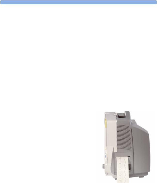
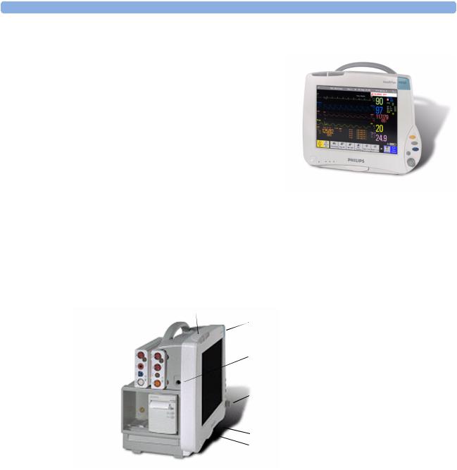
The IntelliVue MP20/MP30 (M8001A/M8002A) patient monitor has a 10-inch TFT LCD flat panel SVGA display. The standard input devices for the MP30 are the Touchscreen and integrated navigation point; the MP20 is supplied with an integrated navigation point only. Up to six waves can be shown on MP20/MP30 Screens (USA - up to four waves). 12 ECG traces can be shown on the 12-Lead ECG Screen.
The MP20/MP30 can be connected to one of the Multi-Measurement Modules (MMS) and any one of the MMS extensions. There is an optional built-in recorder. The Flexible Module Rack (M8048A) and all plug-in modules cannot be used with the MP20/ MP30. With an optional Interface board Bispectral Index (BIS) monitoring is possible.
MP20Junior and MP20L are options of MP20 (M8001A) and are included in the descriptions of MP20 in these Instructions for Use.
2

Introducing the IntelliVue Family
MP20/MP30 Major Parts and Keys
MP20/MP30 left side
1 2
3
 4
4
 5
5
 6
6
 7
7
MP20/MP30 front panel
1 |
2 |
3 |
4 |
5 |
6 |
7 |
1 Basic Operation
1Color-coded alarm lamps
2Alarms off lamp
3Model indicator
4ECG out
5Navigation Point
6Part number and serial number
7Mounting quick-release lever (when this is pressed the monitor is not fixed on the mounting)
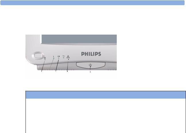
1On/Standby switch
2On/Standby LED
3Error LED
4Battery status LED
5AC power operation LED
6“read the documentation” symbol
7Mounting quick-release lever (when this is pressed the monitor is not fixed on the mounting)
MP20/MP30 LED Colors and their Meanings
On/Standby LED |
Green when monitor is switched on |
|
|
Error LED |
Red if there is a problem with the monitor |
|
|
Battery LED |
Green, yellow, and red. |
|
See the section on Using the Batteries for details |
AC Power LED |
Green while the monitor is connected to AC power (mains) |
|
|
3
1 Basic Operation |
Introducing the IntelliVue Family |
IntelliVue MP40/MP50
The IntelliVue MP40/MP50 (M8003A/M8004A) patient monitor has a 12-inch TFT LCD flat panel SVGA display. The standard input devices for the MP50 are the Touchscreen and integrated navigation point; the MP40 is supplied with an integrated navigation point only. Up to six waves can be shown on MP40/MP50 Screens, 12 ECG traces can be shown on the 12-Lead ECG Screen.
The MP40/MP50 can be connected to one of the MultiMeasurement Modules (MMS) and any one of the MMS extensions. The IntelliVue family plug-in measurement modules can be connected to its four
integrated plug-in module slots with plug-and-play convenience (the only exception is the SvO2 module, M1021A, which cannot be used with the MP40/MP50). The Flexible Module Rack (M8048A) cannot be used with the MP40/MP50.
MP40/MP50 Major Parts and Keys
MP40/MP50 left side
1
1 |
2 |
2 |
|
3 |
|
|
3 |
|
|
|
|
|
|
4 |
|
4 |
5 |
|
|
6 |
5 |
7 |
|
Color-coded alarm lamps
Alarms off lamp
Model indicator
ECG out
Navigation Point
Part number and serial number
Mounting quick-release lever (when this is pressed the monitor is not fixed on the mounting)
8 Plug-in module slots
8 |
6 |
|
7 |
||
|
4
Introducing the IntelliVue Family |
1 Basic Operation |
MP40/MP50 front panel
|
|
1 |
On/Standby switch |
|
|
2 |
On/Standby LED |
|
|
3 |
Error LED |
|
|
4 |
Battery status LED |
|
|
5 |
AC power operation LED |
|
|
6 |
“read the documentation” symbol |
|
|
7 |
Mounting quick-release lever |
1 |
2 3 4 5 6 |
7 |
(when this is pressed the monitor |
is not fixed on the mounting) |
MP40/MP50 LED Colors and their Meanings
On/Standby LED |
Green when monitor is switched on |
|
|
Error LED |
Red if there is a problem with the monitor |
|
|
Battery LED |
Green, yellow, and red. |
|
See the section on Using the Batteries for details |
AC Power LED |
Green while the monitor is connected to AC power (mains) |
|
|
IntelliVue MP60/MP70
The IntelliVue MP60/MP70 (M8005A/M8007A) patient monitors integrate the display unit, with a 15” color LCD display, and the data processing unit into one. Up to eight waves can be shown on the screens, as well as the 12-Lead ECG Screen. The MP60 uses the SpeedPoint as its primary input device while the MP70 uses touch screen operation but may have an optional SpeedPoint.
The monitors can be connected to a Multi-Measurement Modules (MMS) and any one of the MMS extensions, and to the Flexible Module Rack (M8048A). The IntelliVue family plug-in measurement modules can be connected to its FMS module slots with plug-and-play convenience.
The MP60/MP70 has two integrated slots for plug-in modules. You can combine one each of the following modules in these slots: Pressure, Temperature, C.O., BIS, SpO2, VueLink and IntelliBridge. Two of the same type of module cannot be used. You can also use the two-slot recorder module in the integrated slots.
5

1 Basic Operation |
Introducing the IntelliVue Family |
MP60/MP70 Major Parts and Keys
|
|
|
|
|
|
1 |
Color coded alarm lamps |
1 |
|
|
2 |
3 |
4 |
2 |
Alarms Off lamp |
|
|
|
|
|
|
3 |
Display |
|
|
|
|
|
|
4 |
Model indicator |
|
|
|
|
|
|
5 |
SpeedPoint (optional for MP70) |
|
|
|
|
|
|
6 |
Part number and serial number |
|
|
|
|
|
|
7 |
Mounting quick-release lever |
|
|
|
|
|
5 |
|
(when this is pressed the monitor |
|
|
|
|
|
|
|
is not fixed on the mounting) |
|
|
|
|
|
|
8 |
AC power LED |
|
|
|
|
|
|
9 |
Error LED |
|
|
|
|
|
|
10 |
Power on/standby switch |
11 |
10 |
9 |
8 |
7 |
6 |
11 |
Power on LED |
|
|
|
|
|
|
IntelliVue MP80/MP90
Note: The MP80 monitor (M8008A) is not available in the USA.
The IntelliVue MP80/MP90 (M8008A/M8010A) patient monitors have the display and the processing unit as separate components. They offer both touchscreen and the Remote SpeedPoint as standard input devices. The MP80 can display up to 8 waves simultaneously and the MP90 up to 12 waves.
The monitors can be connected to a Multi-Measurement Module (MMS) and any one of the MMS extensions, and to the Flexible Module Rack (M8048A). The IntelliVue family plug-in measurement modules can be connected to its FMS module slots. The MP90 can be connected to two Flexible Module Racks (FMS). The MP90 has the capability for two displays and can have a third main display with the D80 Intelligent Display.
6

Introducing the IntelliVue Family |
1 Basic Operation |
MP80/MP90 Major Parts and Keys
6
5
4
3
2
1
1Display Unit
2Processing Unit
3Power On switch
4Power On LED
5Error LED
6AC Power LED
D80 Intelligent Display
The D80 Intelligent Display can be used as a third main display with the MP90 monitor. You then have three displays able to be configured individually and to be operated independently.
Remote Alarm Device
The Remote Alarm Device provides audio and visual indicators of alarms, in addition to those shown on the display.
7

1 Basic Operation |
Introducing the IntelliVue Family |
1 |
2 |
1
2
 3
3
3
4
5
4 5
Two color coded alarm lamps (right-hand lamp flashes red or yellow for patient alarms, left-hand lamp flashes light blue for INOPs)
Alarms off lamp - when illuminated it indicates that all alarms are deactivated.
Speaker - for alarm tones, QRS tones and so forth
Monitor power on /standby switch. Press to switch monitor on remotely. Press and hold for one second to turn monitor off.
Power on LED - green when monitor is on
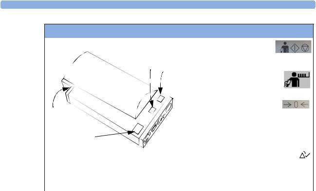
Docking Station
MP20/30/ The docking station provides quick mounting and connections in a one-step operation. By placing the 40/50 only monitor on the docking station and closing the lever you can make the connection to power and to a wired network, if present. Keep the monitor in an upright position when placing it onto the docking
station.
WARNING If the docking station is in a tilted position, use the carrying handle to push the monitor towards the back of the docking station while closing the locking lever.
When using the monitor for transport directly after use on the docking station, insert the batteries before placing the monitor on the docking station.
 4
4
3
2 |
|
1 |
5 |
8
Devices for Acquiring Measurements |
1 Basic Operation |
1Open position
2Power On LED
3Data Connector
4Power Connector
5Locked Position
Devices for Acquiring Measurements
All the patient monitors acquire patient measurements using the devices described in this section. You can also extend the measurement capabilities of your monitor with such devices. Of these measurement devices, only the X2 has its own power on/standby switch, and can be powered from an external power supply or a rechargeable battery in addition to taking power from a host monitor (refer to the IntelliVue X2 Instructions for Use for details). All the rest take their power exclusively from the monitor, and switch on automatically when you turn on the monitor. A green power-on LED indicates when they are drawing power from the monitor. A permanently illuminated, or flashing, red LED indicates a problem with the unit that requires the attention of qualified service personnel.
All symbols used on the front panels are explained in the Installation and Specifications chapter, beginning on page 403.
WARNING When connecting devices for acquiring measurements, always position cables and tubing carefully to avoid entanglement or potential strangulation.
Flexible Module Rack (M8048A)
MP60/70/80 /90 only
The flexible module rack (FMS) lets you use up to eight plug-in physiological measurement modules.
With the MP60/70/80 you can connect only one FMS. With the MP90 (M8010A) you can connect two FMSs to use up to 10 measurement modules. For individual modules, the maximum that can be used simultaneously in an FMS is: five pressure modules, four temperature modules, four VueLink or IntelliBridge modules (any combination).
Connect the FMS to the monitor via the measurement link cable (MSL). Use the MSL connector on the left-hand side to connect an additional MMS. Use the connector on the right to connect to the monitor.
1 |
2 |
3 |
1 |
X1 Multi-Measurement |
|
|
|
|
Module |
|
|
|
|
|
|
|
|
|
|
|
|
|
2 |
Multi-Measurement |
|
|
|
|
Module mount |
|
|
|
3 |
Flexible Module Rack |
|
|
|
4 |
Power on LED |
|
|
|
5 |
Interruption indicator |
|
|
4 |
5 |
|
9

1 Basic Operation |
Devices for Acquiring Measurements |
Measurement Modules
You can use up to eight measurement modules with the Flexible Module Rack (M8048A), two additional modules in the integrated module slots in the MP60/MP70, and up to four in the integrated slots in the MP40/MP50. Available modules are:
•Invasive blood pressure (M1006B)
•Temperature (M1029A)
•Oxygen saturation of arterial blood (SpO2) (M1020B)
•Cardiac output (M1012A), and Continuous cardiac output with M1012A Option #C10
•Transcutaneous gas (M1018A)
•Mixed venous oxygen saturation - SvO2 (M1021A)
•Intravascular Oxygen Saturation - ScvO2 or SvO2 (M1011A)
•Recorder (M1116B)
•VueLink device interface (M1032A)
•IntelliBridge EC10
•EEG (M1027A)
•Bispectral Index - BIS (M1034A)
•Spirometry (M1014A)
You can plug and unplug modules during monitoring. Insert the module until the lever on the module clicks into place. Remove a module by pressing the lever upwards and pulling the module out. Reconnecting a module to the same monitor restores its label and measurement settings, such as alarms limits. If you connect it to a different monitor, the module remembers only its label.
The connector socket on the front of each module is the same color as the corresponding connector plug on the transducer or patient cable.
Press the Setup key on the module’s front to display the measurement’s setup menu on the monitor screen. When the setup menu is open, a light appears above the key. Some modules have a second key. On the pressure module, for example, it initiates a zeroing procedure.
Example Module (Pressure)
1Module name
2Setup key LED
3Setup key to enter setup menu of measurement modules or external device data window
4Connector socket for patient cable/ transducer
5Second module-specific key, for example Zero
PRESS
1
2 Press
Press
3 |
|
|
|
|
|
5 |
|
|
|
|
|
|
|||
|
|
|
|
|
|||
4 |
|
|
|
|
|
|
|
|
|
|
|
|
|
|
|
|
|
|
|
|
|
|
|
|
|
|
|
|
|
|
|
|
|
|
|
|
|
|
|
|
|
|
|
|
|
|
|
|
|
|
|
|
|
|
|
|
|
|
|
|
|
|
|
|
|
|
|
|
|
|
|
10
Devices for Acquiring Measurements |
1 Basic Operation |
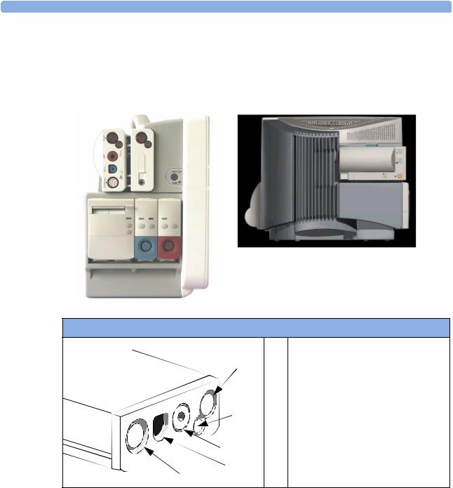
X1 Multi-Measurement Module (M3001A)
The X1 Multi-Measurement Module (MMS) can simultaneously monitor 3-, 5-, 6- or 10-lead ECG (including arrhythmia and ST monitoring), respiration, SpO2, NBP and either invasive pressure or temperature. Depending on the monitor model, you can connect it to the monitor via a cable or mount it either on the left side of the FMS or on the back of the monitor, as shown here.
M3001A Connectors and Symbols
|
1 |
White ECG/Resp connector |
|
|
|
5 |
2 |
Blue SpO2 connector |
|
3 |
Red NBP connector |
|
|
|
|
4 & Combined pressure (red) and temperature |
|
|
5 |
(brown) connector - connect either invasive |
4 |
|
pressure transducer or temperature probe. |
|
|
You might have a version of the MMS that |
|
|
does not have this connector. |
3 |
|
|
 2
2
 1
1
11
1 Basic Operation |
Devices for Acquiring Measurements |
M3001A Connectors and Symbols
|
|
|
6 |
|
|
|
|
|
NBP Start/Stop key -starts |
6 |
|
|
or stops NBP measurements |
|
7 |
|
|
||
7 |
|
|||
|
|
|
||
|
|
|
|
NBP STAT key - starts NBP |
|
|
|
|
|
|
|
|
|
|
|
|
|
|
STAT series of measurements |
9 |
|
|
|
|
|
|
|
OR |
|
|
|
|
|
Zero key - initiates a zero procedure for the |
|
|
|
|
connected pressure transducer when |
8 |
|
|
|
pressed and held for a second |
|
|
|
|
|
|
|
|
8 |
|
|
|
|
|
Silence: acknowledges all active |
|
|
|
|
alarms by switching off audible |
|
|
|
|
alarm indicators and lamps |
|
|
|
|
|
|
|
|
9 |
MSL cable connector to the monitor |
|
|
|
|
|
12

Devices for Acquiring Measurements |
1 Basic Operation |
X2 Multi-Measurement Module (M3002A)
The X2 Multi-Measurement Module (MMS) can simultaneously monitor 3-, 5-, 6- or 10-lead ECG (including arrhythmia and ST monitoring), respiration, SpO2, NBP and either invasive pressure and temperature, or CO2. It has a color touchscreen display.
The X2 has the added capability to operate as a stand-alone monitor, and can be powered by a rechargeable battery. This makes it particularly suited to transport situations. When the X2 is disconnected from the original host monitor, it continues to monitor the patient as a stand-alone monitor running on battery power, eliminating the need for a separate transport monitor. When the X2 is connected to a new host monitor, it resumes its role as MMS, ensuring fully continuous monitoring. For details of using the X2 as a stand-alone monitor, refer to the IntelliVue X2 Instructions for Use.
When connected to a host monitor (Companion Mode is indicated), the X2 takes power from the host, including that required for battery charging. The X2 can also be powered by AC mains when not connected to a host monitor using the optionally available external power supply (M8023A). See the
IntelliVue X2 Instructions for Use for details.
X2 Overview
|
|
1 |
|||
4 |
5 |
|
|
2 |
|
|
|
|
|||
|
|
6 |
|
3 |
|
|
|
|
|
||
|
|
|
|
|
4 |
|
|
|
|
|
7 |
|
|
|
|
|
5 |
|
|
|
|
|
6 |
|
|
|
|
|
|
3 |
|
|
|
7 |
|
|
|
|
|
|
|
2 |
|
|
|
8 |
|
|
|
|
8 |
||
1 |
|
|
|
||
|
|
|
|
|
|
On/Standby Switch
Power and battery indicators (see “X2 Controls and Indicators” on page 14)
3.5-inch TFT LCD touchscreen QVGA display
Alarm lamps (see “X2 Controls and Indicators” on page 14)
Battery eject button
Hard keys (see “X2 Controls and Indicators” on page 14)
Measurement connectors (see “X2 Patient Connectors, Right Side” on page 14)
Battery compartment
13

1 Basic Operation |
Devices for Acquiring Measurements |
X2 Controls and Indicators
6 7
5
4
3
2
1 On/Standby switch
82 On/Standby LED. Green when monitor is on. Red indicates an error.
3 Battery status LED. Yellow when
9charging. Flashing red when battery is empty.
4 External power LED. Green when
10monitor is powered from an external power source.
115 Alarms off indicator. When alarms are suspended, the lamp is red, and the
alarms off symbol is shown.
6Active INOP alarm lamp in light blue. Blinks until active INOP is acknowledged.
7Active alarm lamp. Red or yellow, depending on alarm level. Blinks until active alarm is acknowledged.
8Silence key
9Alarms key: turns alarms On/Off, or
pauses them
110 Smartkeys key: brings up Smartkeys on the screen
11Main Screen key: closes all open menus/windows and returns to the main screen.
X2 Patient Connectors, Right Side
Showing symbols version (international) and text version (English only)
1 |
|
|
|
|
|
|
|
|
|
|
|
|
|
|
|
|
|
|
1 |
|
|
|
|
|
|
|
|
|
|
|
|
|
|
|
|
|
|
|
|||
|
|
|
|
|
|
|
|
|
|
|
|
|
|
|
|
|
|
|||
|
|
|
|
|
|
|
|
|
|
|
|
2 |
||||||||
|
|
|
|
|
|
|
|
|
|
|
|
|||||||||
|
|
|
|
|
|
|
|
|
|
|
|
|||||||||
|
|
|
|
|
|
|
|
|
|
|
|
|||||||||
|
|
|
|
|
|
|
|
|
|
|
|
|||||||||
|
|
|
|
|
|
|
|
|
|
|
|
|
||||||||
|
|
|
|
|
|
|
|
|
|
|
|
|
|
|
|
|
|
|
|
|
2 |
|
|
|
7 |
|
|
|
|
|
|
|
|
|
|
|
|||||
|
|
|
|
|
|
|
|
|
|
|
|
|
|
|
||||||
3 |
||||||||||||||||||||
|
||||||||||||||||||||
3 
4
5
4
5 |
6 |
|
|
6 |
|
1Pressure (option)
2Temperature (option)
3Noninvasive blood pressure
4SpO2
5ECG sync pulse output
6ECG/Respiration
7CO2 (option in place of Pressure and Temperature)
14

Devices for Acquiring Measurements |
1 Basic Operation |
X2 Left Side
1 Loudspeaker
2 MSL Connector. Connects to the external power supply or a host monitor via the MSL cable for AC mains operation, battery charging, and communication with a network.
1
2
Depending on the monitor model, you can connect the X2 to the monitor via a cable or mount it either on the left side of the FMS or on the back of the monitor, as shown here.
MMS Extensions
The MMS extensions connect to the MMS and use the MMS settings and power. Trend data and measurement settings from the measurements in the extensions are stored in the MMS.
WARNING • The MMS extensions can only function when they are connected to an MMS. If the MMS is removed during monitoring, the measurements from both the MMS and the extension are lost.
•Measurements from a MMS extension connected to an X2 are not available when the X2 is running on battery power. They are only available when the X2 is powered from AC mains, either when connected to a host monitor or the external power supply (M8023A).
To separate an extension from the MMS, press the release lever down, and push the MMS forward.
15

1 Basic Operation |
|
Devices for Acquiring Measurements |
|
|
|
|
|
|
M3014A, M3015A and M3016A Capnography MMS Extensions
The optional M3014A Capnography extension adds mainstream capnography or sidestream capnography, and optionally one pressure plus either a pressure or a temperature, Cardiac Output and Continuous Cardiac Output to the MMS. The optional M3015A Microstream CO2 extension adds microstream capnography and optionally either pressure or temperature to the MMS. The optional M3016A Mainstream CO2 extension adds mainstream capnography and optionally either pressure or temperature to the MMS.
When a capnography extension is connected to an X2 MMS with CO2, the CO2 from the extension will be automatically deactivated. The cardiac output measurement is deactivated when the extension is used with an X2 MMS unless the X2 is connected to a host monitor.
16

Devices for Acquiring Measurements |
1 Basic Operation |
M3014A |
M3015A |
1 |
1 |
2
4
3 |
2 |
7 |
6 |
5 |
M3016A
1
3 
|
|
2 |
|
1 |
Pressure connectors (red) |
5 |
Inlet |
2 |
Temperature connector (brown) |
6 |
Microstream connector CO2 |
3 |
Mainstream/sidestream connector CO2 |
7 |
Gas sample outlet |
|
(optional) |
|
|
4 |
Cardiac Output connector |
|
|
17

1 Basic Operation |
Devices for Acquiring Measurements |
M3012A Hemodynamic MMS Extension
2
3
1 |
4 |
|
1Cardiac Output (orange; optional)
2Connection to MMS
3Pressure connectors (red)
4Temperature connectors (brown)
The M3012A Hemodynamic extension can be connected to the M3001A Multi-Measurement Module to provide the following additional measurements: Temperature, Pressure, an additional Pressure or Temperature, and C.O. and CCO measurements.
The cardiac output measurement is deactivated when the extension is used with an X2 MMS unless the X2 is connected to a host monitor.
18
Loading...