How it Works
Log In / Sign Up
0
My Files
0
My Downloads
184560
History
Account Settings
Log Out
Buy Points
How it Works
FAQ
Contact Us
Questions and Suggestions
Users
show menu
Philips
Loading...
E
EL-3547
EL-3553
EL-3555
EL-3585
EL-3586
EL2
el3542a
el6411
Electromagnetic Lamp
ELEGANCE 44
Elektrorasierer
Elevation Televisor Smart LED ultrafino
EM1.1A
EM1.1A AA
EM1.1U AA
EM1.2U
EM1A
EM1A AA
EM1L
EM2E
EM2E A3
EM2E AA
EM3E
EM43
EM5.1E
EM5.1E AA
EM5.3E AA
EM5E
EM5E AA
EM7
EM8E
Emerson CoughAssist CA
Emerson CoughAssist E70
Emerson LC391EM3
EMERSON LF501EM4
EMUSA013MENBICO
EN 32HFL3331-93
EN BDP3200
enceinte portable sans fil
Enceinte sans fil SoundRing
Enceinte stéréo sans fil
Energy Advantage
Energy Saver Compact Fluorescent Lamp
Enterprise Transcribe 4.5
EP 1220/00
2
EP 1224/00
EP 3243/70
EP 3246/70
3
EP 3519/00
EP 5315/10
EP1.1UAA
EP1000
EP1200
EP1200-00
2
EP1224
EP2020
EP2021
EP2030
EP2035
EP2220-10
2
EP2220-19
EP2220-40
EP2221-40
2
EP2224-10
2
EP2230-10
EP223014
EP2231
EP2231-40
EP2235-40
EP2236-40
EP3221-40
EP322144
EP3241
EP3241-50
EP324154
EP3243
2
EP3243-50
EP3246
2
EP3249-70
EP3363
EP3363-00
EP3559
EP4050
EP4321-50
EP4341-50
EP4349
EP5030/10
EP5064-10
EP5310
EP5360-10
EP5444
EP5447
EP5934
2
EP5960
EP5961
ES1B
ES1E AA
EverFlo
EXP-210
EXP-320
Loading...
Loading...
Nothing found
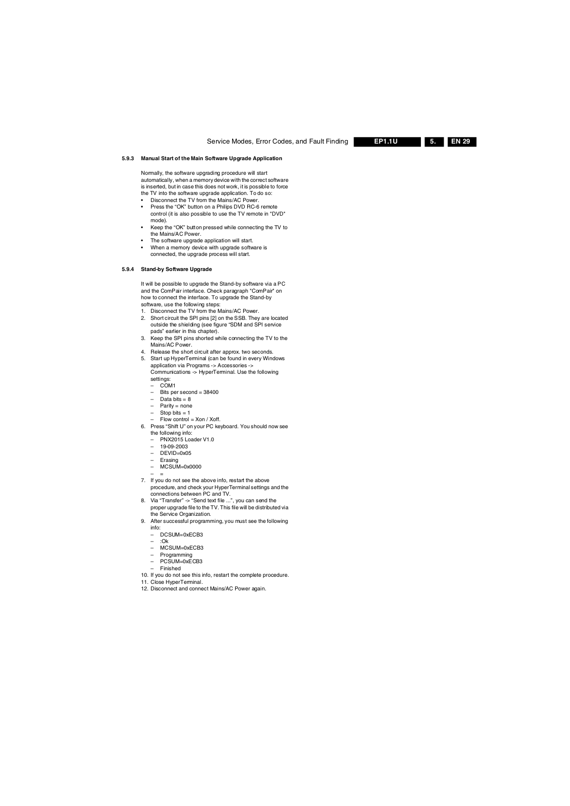
EP1.1UAA
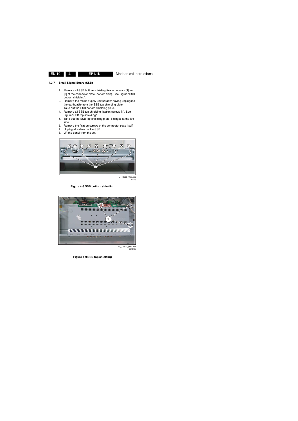
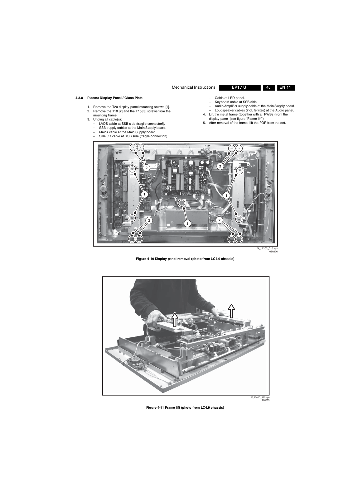
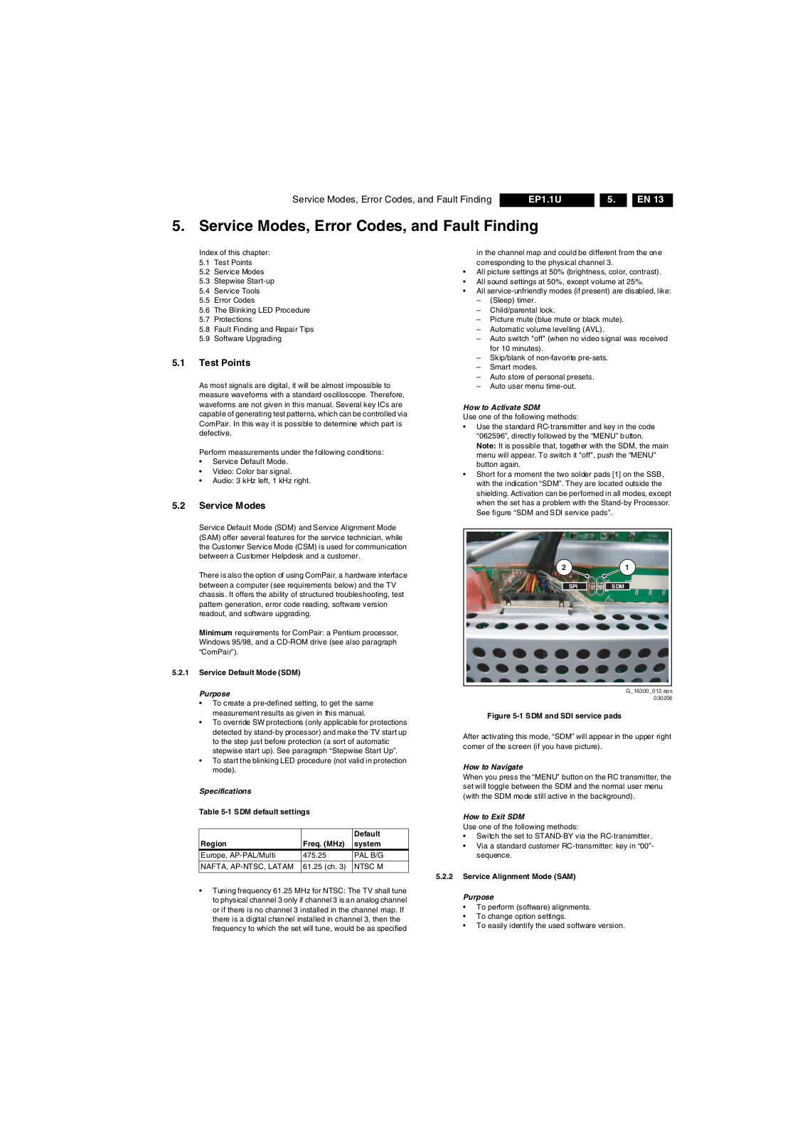
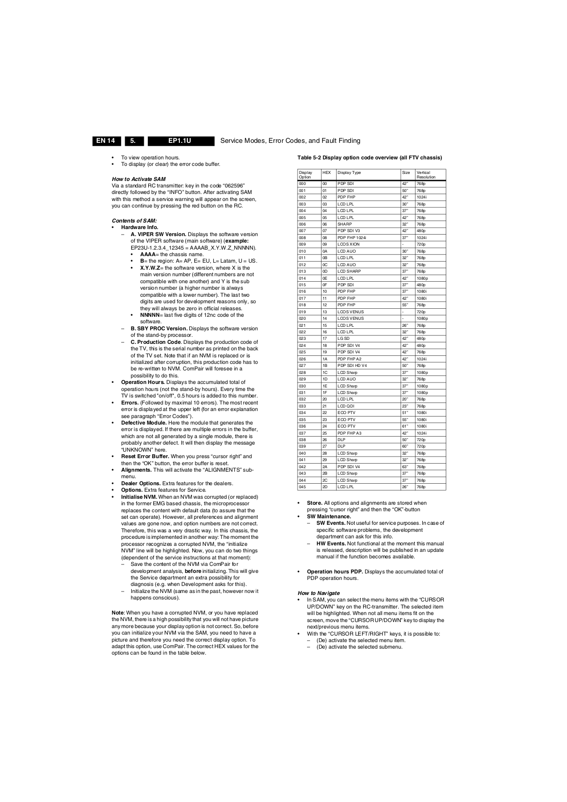
Service Manual
101 pgs
13.42 Mb
0
Table of contents
Loading...
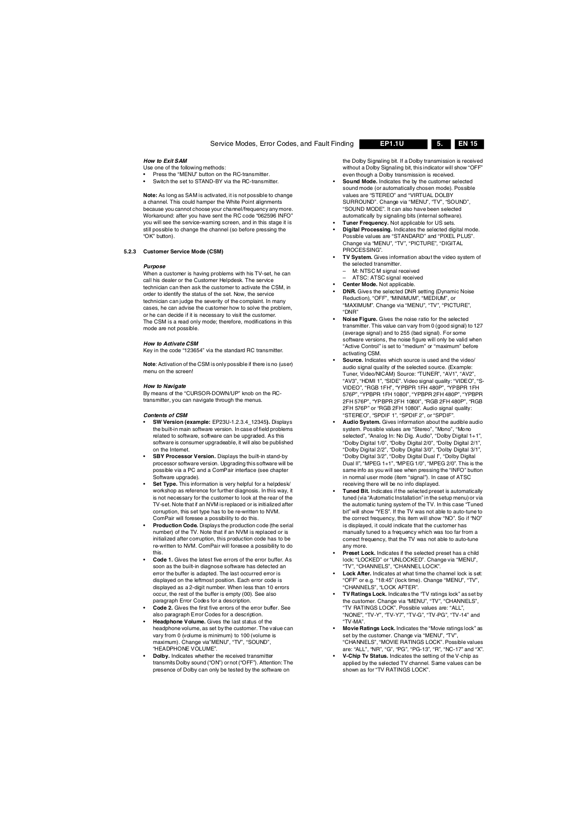
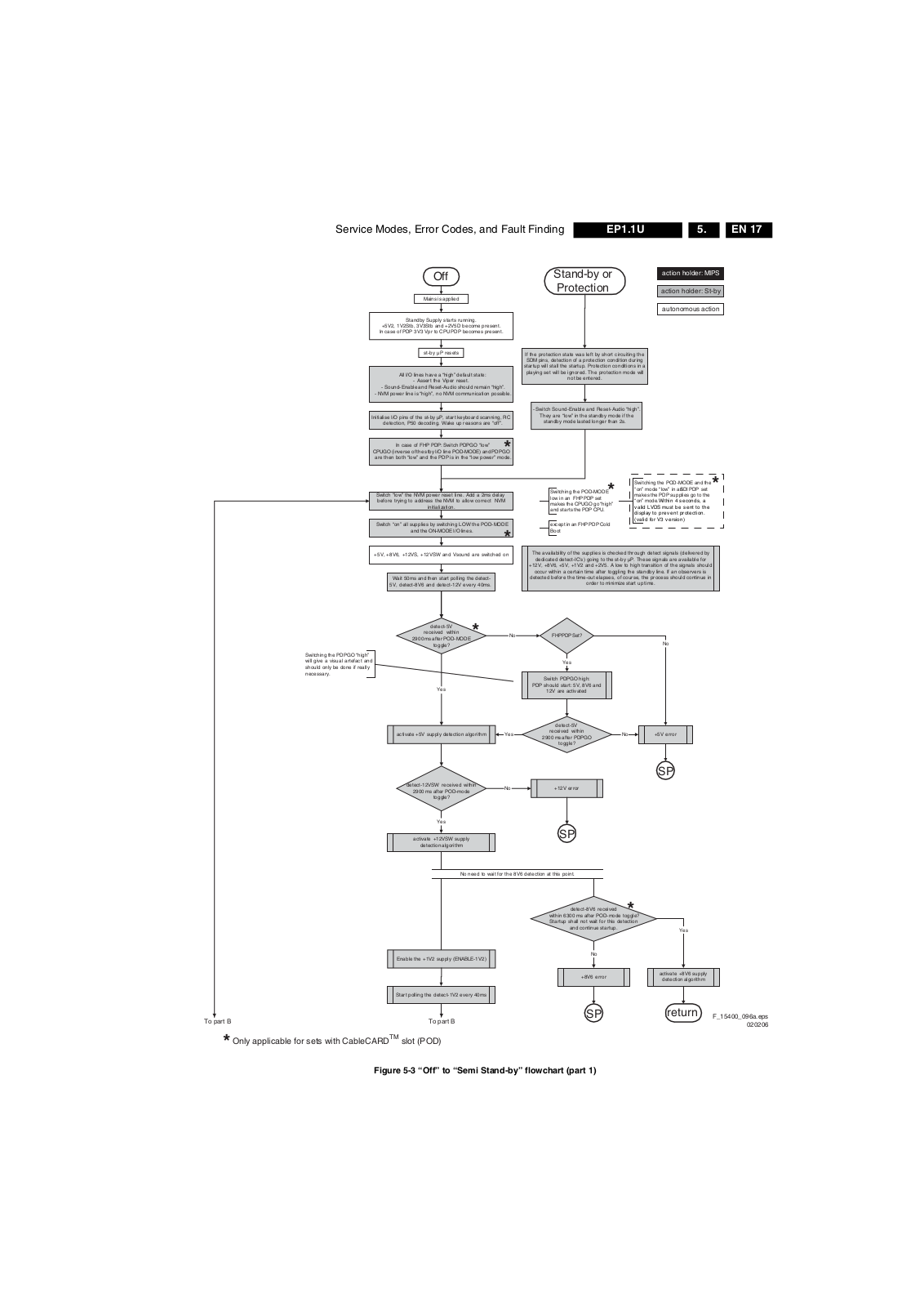
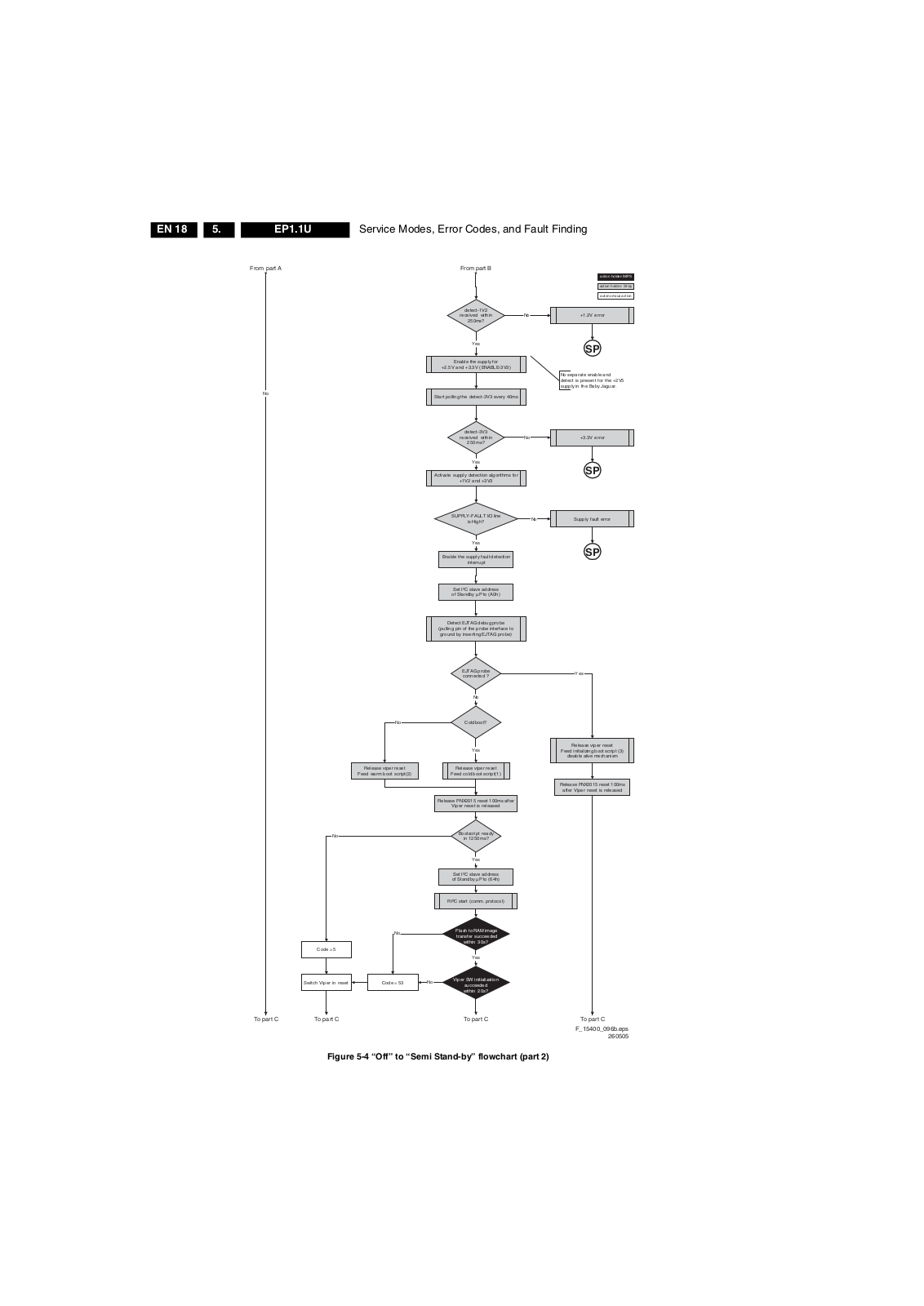
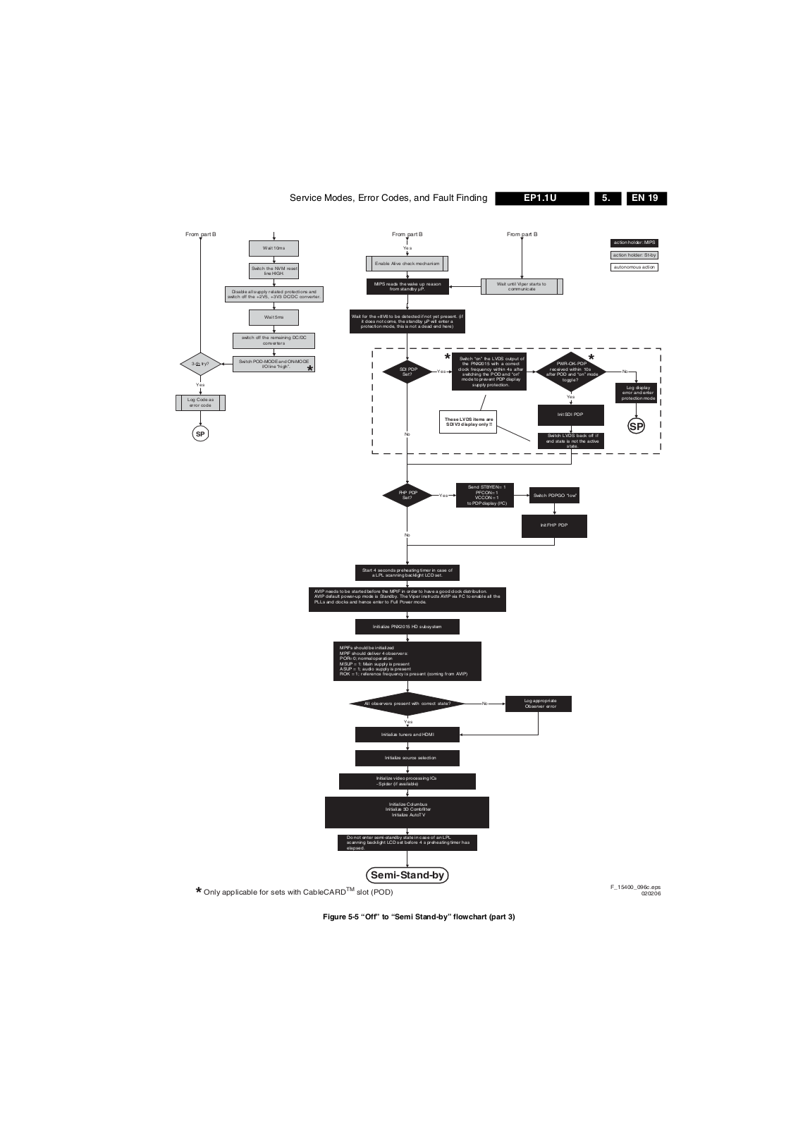
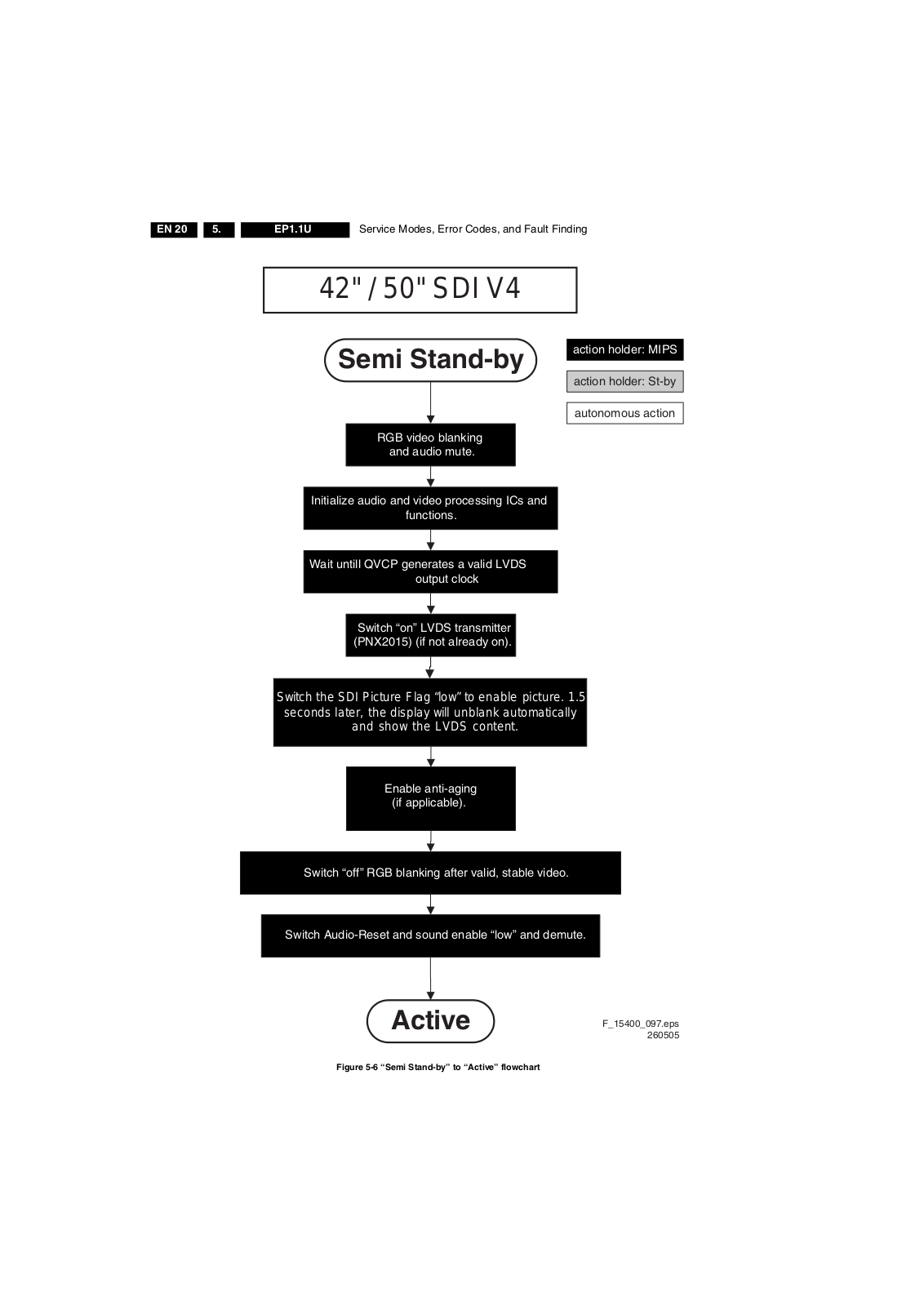
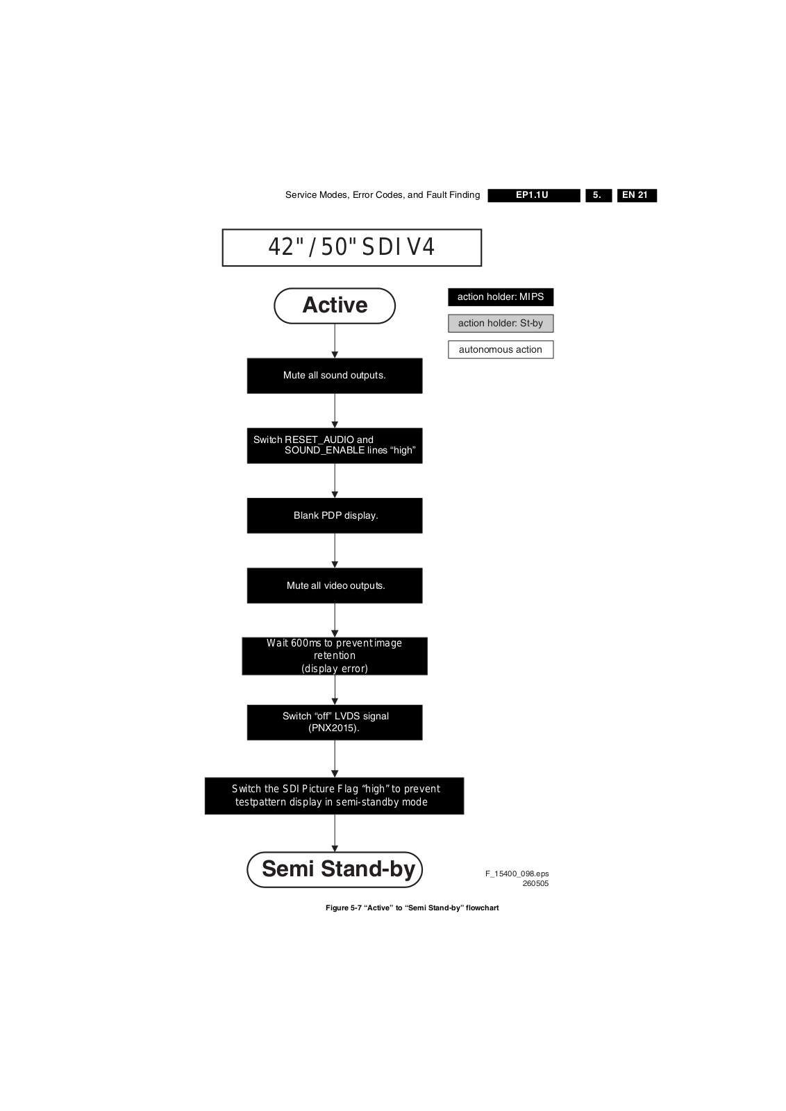
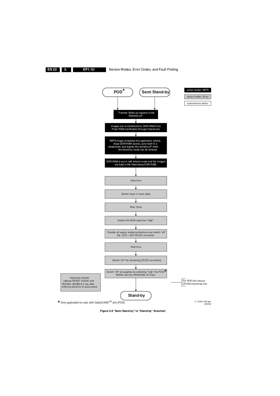
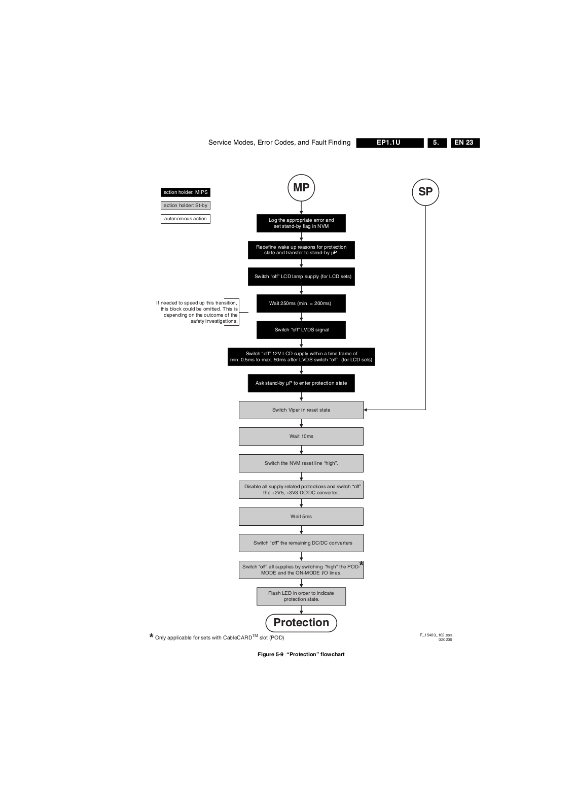
Philips EP1.1UAA Service Manual
...
Philips Service Manual
Download
0
(
0
)
Loading...
+
71
hidden pages
Unhide
You need points to download manuals.
1 point = 1 manual.
You can buy points or you can get point for every manual you upload.
Buy points
Upload your manuals


 Loading... Loading...