


Colour Television |
Chassis |
EM1A
AA
CL 06532111_000.eps
171000
Contents |
|
Page |
|
|
1. Technical specifications, connection facilities & |
|
|
||
|
chassis overview |
|
2 |
|
2. |
Safetyand maintenance instructions, |
4 |
|
|
|
warnings and notes. |
|
|
|
3. |
Directions for use |
|
6 |
|
4. |
Mechanical instructions |
|
11 |
|
5. |
Faultfinding and repair tips |
|
15 |
|
6. Block-, wiring diagrams and testpoint overviews |
|
|
||
|
Blockdiagram video processing |
|
27 |
|
|
Blockdiagram audio & control |
|
28 |
|
|
Blockdiagram Large Signal Panel: supply |
29 |
|
|
|
Powerlines overview |
|
30 |
|
|
Wiring diagram |
|
31 |
|
|
I2C overview |
|
32 |
|
|
Testpoint overview LSP |
|
33 |
|
|
Testpoint overview SSB / DW / CRT panel |
34 |
|
|
7. Electrical diagram’s en PWB’s |
|
Diagram PWB |
||
|
Main supply |
(Diagram A1) |
35 |
43-48 |
|
Standby supply |
(Diagram A2) 36 |
43-48 |
|
|
Line deflection |
(Diagram A3) |
37 |
43-48 |
|
Frame deflection |
(Diagram A4) |
38 |
43-48 |
|
Audio amplifier |
(Diagram A5) |
39 |
43-48 |
|
Headphone amplifier |
(Diagram A6) 40 |
43-48 |
|
|
Tuner, I/O, SIMM-connector |
(Diagram A7) |
41 |
43-48 |
|
Front control |
(Diagram A8) |
42 |
43-48 |
|
SSB: SIMM-connector |
(Diagram B1) |
49 |
55-60 |
|
IF, I/O, videoprocessing |
(Diagram B2) |
50 |
55-60 |
|
Feature box |
(Diagram B3) |
51 |
55-60 |
|
HOP |
(Diagram B4) |
52 |
55-60 |
|
Audio demodulator |
(Diagram B6) 53 |
55-60 |
|
|
Painter |
(Diagram B7) |
54 |
55-60 |
|
Multi PIP controller |
(Diagram C1) |
61 |
65/66 |
|
Tuner |
(Diagram C2) |
62 |
65/66 |
|
I/O processing |
(Diagram C3) 63 |
65/66 |
|
©Copyright 2000 Philips Consumer Electronics B.V. Eindhoven, The Netherlands. All rights reserved. No part of this publication may be reproduced, stored in a retrieval system or transmitted, in any form or by any means, electronic, mechanical, photocopying, or otherwise without the prior permission of Philips.
Published by CO 0070 Service PaCE |
Printed in the Netherlands |
Contents |
|
Page |
|
|
|
|
|
|
|||
|
IF video sync |
(Diagram C4) |
64 |
65/66 |
|
|
Side I/O panel |
(Diagram D) |
67 |
67 |
|
|
Top control panel |
(Diagram E) |
69 |
69 |
|
|
CRT panel |
(Diagram F) |
70 |
71 |
|
|
DC-shift panel |
(Diagram G) |
71 |
71 |
|
|
Horizontal DAF panel |
(Diagram I1) |
72 |
74 |
|
|
Vertical DAF panel |
(Diagram I2) |
73 |
74 |
|
|
Mains switch panel |
(Diagram J) |
75 |
75 |
|
|
Mains harmonic panel |
(Diagram Y) |
76 |
76 |
|
8. |
Alignments |
|
77 |
|
|
9. |
Circuit description and |
|
82 |
|
|
|
list of abbreviations |
|
96 |
|
|
10. |
Spareparts list |
|
98 |
|
|
Subject to modification |
3122 785 10850 |
GB 2 |
|
1. |
|
EM1A |
Technical specifications, connection facilities & chassis overview |
1. Technical specifications, connection facilities & chassis overview
1.1 Technical specifications |
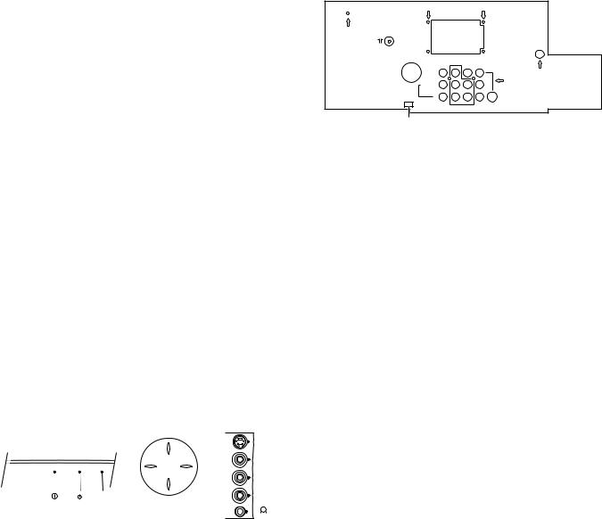
1.2.2 Rear connections |
1.1.1 |
Reception |
|
|
|
|
|
|
Tuning system |
: |
PLL |
75Ω |
|
|
|
Colour systems (off-air) |
: |
NTSC M (3.58 & |
|
|
|
|
|
|
|
|||
|
|
|
4.43 MHz), |
MONITOR |
AV1 |
AV2 |
|
|
: |
PAL B/G/D/K/I/M/N, |
|||
|
|
OUT |
IN |
IN |
||
|
|
: SECAM B/G/D/K/L |
VIDEO |
|
|
|
|
|
|
Y |
|
||
|
Sound systems |
: FM/FM, |
L/MONO |
|
S-VIDEO |
|
|
AUDIO |
Pb |
||||
|
|
: 2SC B/G, |
R |
|
|
|
|
|
|
Pc |
|
||
|
|
: |
NICAM B/G/D/K/I/L |
COMPONENT VIDEO INPUT |
||
|
|
|
|
CL 06532130_001.eps |
||
|
A/V connections |
: |
PAL B/G, |
SERVICE |
|
|
|
CONNECTOR |
|
021000 |
|||
|
|
: SECAM, |
|
|
|
|
|
|
: NTSC M (3.58 & |
Figure 1-2 |
|||
|
|
|
4.43 MHz). |
|
|
|
Channel selections |
: |
100 channels, |
Monitor out |
|
|
||
|
: |
UVSH-channels |
|
|
|||
|
1 |
- Video |
1 Vpp / 75 Ω |
|
|||
Frequency range |
: |
44.25 - 855.25 MHz |
|||||
2 |
- Audio |
L (0.5 Vrms / 10 kΩ) |
|
||||
Aerial input |
: |
75 Ω, Coax |
|||||
3 |
- Audio |
R (0.5 Vrms / 10 kΩ) |
|
||||
|
|
|
|||||
1.1.2 Miscellaneous |
|
|
AV1 in |
|
|
||
|
|
|
|
|
|||
Set stroke numbers |
: |
/56, /57, /69, /79, |
1 |
- Y |
0.7 Vpp / 75 Ω |
|
|
2 |
- Pb |
0.7 Vpp / 75 Ω |
|
||||
|
|
/93 |
3 |
- Pr |
0.7 Vpp / 75 Ω |
|
|
Mains voltage |
: |
160 - 276 V |
|
|
|
|
|
|
|
(± 10 %), |
AV1 in |
|
|
||
|
: |
50 / 60 Hz (± 5 %) |
|
|
|||
|
4 |
- Video |
1 Vpp / 75 Ω |
|
|||
Ambient temperature |
: |
+ 5 to + 45 deg. C. |
|||||
5 |
- Audio |
L (0.5 Vrms / 10 kΩ) |
|
||||
Standby Power consumption |
: < 1 W. |
||||||
6 |
- Audio |
R (0.5 Vrms / 10 kΩ) |
|
||||
|
|
|
|||||
1.2 Connection facilities |
|
|
|
|
|
|
|
|
|
|
|
|
|
AV2 in |
1 Vpp / 75 Ω |
|
|||||||||||||
|
|
|
|
|
|
|
|
|
|
|
|
|
|
|
|
|
|
|
|
|
|
|
|
|
1 |
- Video |
|||
1.2.1 Control buttons & Side I/O connections |
2 |
- Audio |
L (0.5 Vrms / 10 kΩ) |
|
|||||||||||||||||||||||||
3 |
- Audio |
R (0.5 Vrms / 10 kΩ) |
|
||||||||||||||||||||||||||
|
|
|
|
|
|
|
|
|
|
|
|
|
|
|
|
|
|
|
|
|
|
|
|
|
|||||
|
|
FRONT CONTROL |
|
TOP CONTROL |
|
SIDE I/O |
AV2 in (SVHS) |
|
|
||||||||||||||||||||
|
|
|
|
|
|
|
|
|
|
|
P+ |
|
|
|
|
|
|
|
|
|
|
|
|
|
1 |
- |
gnd |
|
|
|
|
|
|
|
|
|
|
|
|
|
|
|
|
|
|
|
|
|
|
|
|
|
|
||||||
|
|
|
|
|
|
|
|
|
|
|
|
|
|
|
|
|
|
|
|
S-Video |
2 |
- |
gnd |
|
|||||
|
|
|
|
|
|
|
|
|
|
|
|
|
|
|
|
|
|||||||||||||
|
|
|
|
|
|
|
|
|
|
|
|
|
|
|
|
|
|
|
|
|
|
|
|
|
|||||
|
|
|
|
|
|
|
|
|
|
|
V- |
V+ |
|
|
|
|
|
|
|
Video |
3 |
- Y |
1 Vpp / 75 Ω |
|
|||||
|
|
|
|
|
|
|
|
|
|
|
|
|
|
|
|||||||||||||||
|
|
|
|
|
|
|
|
|
|
|
|
|
|
|
|
|
|
|
|
|
|
|
4 |
- C |
0.3 Vpp / 75 Ω |
|
|||
|
|
|
|
|
|
|
|
|
|
|
|
|
|
|
|
|
|
|
|
L |
|||||||||
|
|
|
|
|
|
|
|
|
|
|
|
|
|
|
|
|
|
|
|
Audio |
|
|
|
|
|||||
|
|
|
|
|
|
|
|
|
IR |
|
P- |
|
|
|
|
|
|
|
|
R |
|
|
|
|
|||||
|
|
|
|
|
|
|
|
|
|
|
|
|
|
||||||||||||||||
|
|
|
|
|
|
|
|
|
|
|
|
|
|
|
|
||||||||||||||
|
|
|
|
|
|
|
|
|
|
|
|
|
|
||||||||||||||||
|
|
|
|
|
RED |
|
|
|
|
|
|
|
|
|
|
|
|
|
|
|
|
|
|
||||||
|
|
|
|
|
|
|
|
|
|
|
|
|
|
|
|
|
|
|
|
|
|
|
|
||||||
|
|
|
|
|
|
|
|
|
|
|
|
|
|
|
|
|
|
|
|
|
|
|
|
|
|
|
|
|
|
|
|
|
|
|
|
|
|
|
|
|
|
|
|
|
|
|
|
|
|
|
|
|
|
|
|
|
|
|
|
|
|
|
|
|
|
|
|
|
|
|
|
CL 06532130_002.eps |
|
|
|
|
|||||||||||||
|
|
|
|
|
|
|
|
|
|
|
|
031000 |
|
|
|
|
|||||||||||||
|
|
|
|
|
|
|
|
|
|
|
Figure 1-1 |
|
|
|
|
|
|
|
|
|
|
|
|
|
|
|
|
|
|
|
|
SVHS |
|
|
|
|
|
|
|
|
|
|
|
|
|
|
|
|
|
|
|
||||||||
1 |
- |
|
|
|
|
|
|
gnd |
|
|
|
|
|
|
|
|
|
|
|
|
|
|
|
|
|
||||
2 |
- |
|
|
|
|
|
|
gnd |
|
|
|
|
|
|
|
|
|
|
|
|
|
|
|
|
|
||||
3 |
- Y |
1 Vpp / 75 Ω |
|
|
|
|
|
|
|
|
|
|
|
|
|
|
|
|
|
||||||||||
4 |
- C |
0.3 Vpp / 75 Ω |
|
|
|
|
|
|
|
|
|
|
|
|
|
|
|
|
|
||||||||||
|
|
Audio / video |
|
|
|
|
|
|
|
|
|
|
|
|
|
|
|
|
|
|
|
||||||||
1 |
- Video |
1 Vpp / 75 Ω |
|
|
|
|
|
|
|
|
|
|
|
|
|
|
|
||||||||||||
2 |
- Audio |
L (0.2 Vrms / 10 kΩ) |
|
|
|
|
|
|
|
|
|
|
|
|
|
|
|
||||||||||||
3 |
- Audio |
R (0.2 Vrms / 10 kΩ) |
|
|
|
|
|
|
|
|
|
|
|
|
|
|
|
||||||||||||
4 |
- Headphone |
32 - 2000 Ω / 10 mW |
|
|
|
|
|
|
|
|
|
|
|
|
|
|
|
||||||||||||
Technical specifications, connection facilities & chassis overview |
EM1A |
|
1. |
|
GB 3 |
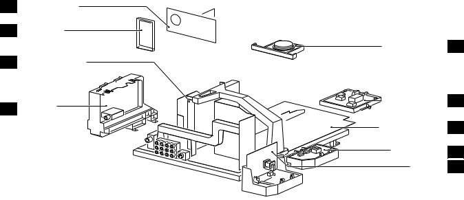
1.3Chassis overview
F
D
B
C
CRT/SCAVEM PANEL |
|
SIDE I/O PANEL |
|
TOP CONTROL PANEL |
E |
SMALL SIGNAL BOARD |
|
MAINS SWITCH PANEL |
J |
PIP/DOUBLE |
|
WINDOW PANEL |
|
LARGE SIGNAL PANEL |
A |
MAINS HARMONIC |
Y |
PANEL |
|
DAF PANEL |
I |
CL 06532130_003.eps
181000
Figure 1-3

GB 4 |
|
2. |
|
EM1A |
Safety & maintenance instructions, warnings and notes |
2. Safety & maintenance instructions, warnings and notes
2.1Safety instructions for repairs
Safety regulations require that during a repair:
•Safety components, indicated by the symbol ∆, should be replaced by components identical to the original ones;
•When replacing the CRT, safety goggles must be worn.
Safety regulations require that after a repair, the set must be returned in its original condition. In particular attention should be paid to the following points:
•General repair instruction: as a strict precaution, we advise you to resolder the solder joints, through which the horizontal deflection current is flowing, in particular:
–All pins of the line output transformer (LOT);
–Fly-back capacitor(s);
–S-correction capacitor(s);
–Line output transistor;
–Pins of the connector with wires to the deflection coil;
–Other components through which the deflection current flows.
Note: This resoldering is advised to prevent bad connections due to metal fatigue in solder joints and is therefore only necessary for television sets older than 2 years.
•The wire trees and EHT cable should be routed correctly and fixed with the mounted cable clamps.
•The insulation of the mains lead should be checked for external damage.
•The mains lead strain relief should be checked for its function in order to avoid touching the CRT, hot components or heat sinks.
•The electrical DC resistance between the mains plug and the secondary side should be checked (only for sets which have a mains isolated power supply). This check can be done as follows:
–Unplug the mains cord and connect a wire between the two pins of the mains plug;
–Set the mains switch to the 'ON' position (keep the mains cord unplugged!);
–Measure the resistance value between the pins of the mains plug and the metal shielding of the tuner or
the aerial connection on the set. The reading should be between 4.5 MΩ and 12 MΩ.
–Switch off the TV and remove the wire between the two pins of the mains plug.
•The cabinet should be checked for defects to avoid touching of any inner parts by the customer.
2.2Maintenance instructions
It is recommended to have a maintenance inspection carried out by a qualified service employee. The interval depends on the usage conditions:
•When the set is used under normal circumstances, for example in a living room, the recommended interval is 3 to 5 years.
•When the set is used in circumstances with higher dust, grease or moisture levels, for example in a kitchen, the recommended interval is 1 year.
•The maintenance inspection contains the following actions:
–Execute the above-mentioned 'general repair instruction'.
–Clean the power supply and deflection circuitry on the chassis.
–Clean the picture tube panel and the neck of the picture tube.
2.3Warnings
•In order to prevent damage to IC's and transistors, all high-voltage flashovers must be avoided. In order to prevent damage to the picture tube, the method shown in Fig. 2-1 should be used to discharge the picture tube. Use a high-voltage probe and a multimeter (position VDC). Discharge until the meter reading is 0 V (after approx. 30 s).
V
CL 26532098/042 140792
Figure 2-1
•All IC's and many other semiconductors are susceptible to electrostatic discharges (ESD). Careless handling during repair can reduce life drastically. When repairing, make sure that you are connected with the same potential as the mass of the set by a wristband with resistance. Keep components and tools also at this same potential. Available ESD protection equipment:
–Complete kit ESD3 (small table mat, wristband, connection box, extension cable and earth cable) 4822 310 10671.
–Wristband tester 4822 344 13999.
•Together with the deflection unit and any multipole unit, the used flat square picture tubes form an integrated unit. The deflection and the multipole units are set optimally at the factory. Adjustment of this unit during repair is therefore not recommended.
•Be careful during measurements in the high-voltage section and on the picture tube.
•Never replace modules or other components while the unit is switched ON.
•When making settings, use plastic rather than metal tools. This will prevent any short circuits and the danger of a circuit becoming unstable.

Safety & maintenance instructions, warnings and notes |
EM1A |
|
2. |
|
GB 5 |
2.4Notes
•The direct voltages and oscillograms should be measured with regard to the tuner earth ( ), or hot earth ( ) as this is called.
•The direct voltages and oscillograms shown in the diagrams are indicative and should be measured in the Service Default Mode (see chapter 5) with a colour bar signal and stereo sound (L: 3 kHz, R: 1 kHz unless stated otherwise) and picture carrier at 475.25 MHz.
•Where necessary, the oscillograms and direct voltages are measured with ( ) and without ( ) aerial signal.
Voltages in the power supply section are measured both for normal operation ( ) and in Standby ( ). These
values are indicated by means of the appropriate symbols.
•The picture tube PWB has printed spark gaps. Each spark gap is connected between an electrode of the picture tube and the Aquadag coating.
•The semiconductors indicated in the circuit diagram and in the parts lists are completely interchangeable per position with the semiconductors in the unit, irrespective of the type indication on these semiconductors.
•DOLBY, the double D symbol and PRO LOGIC are trademarks of Dolby Laboratories Licensing Corporation. Manufactured under license from Dolby Laboratories Licensing Corporation.
Installation
DB
|
|
P I P |
S |
A/CH |
æ |
ß |
ê |
|
|
|
PIP CH |
q |
© |
UP |
DN |
|
1 |
2 |
3 |
|
|
4 |
5 |
6 |
|
return |
7 |
8 |
9 |
|
SMART |
0 |
SMART |
|
|
|
M |
a |
|
|
|
MENU |
|
SURF |
select menu |
|
|
|
|
item |
switch menu off
iV  ¬
¬  CH
CH
PICTURE
SOUND
FEATURES
INSTALL
INSTALL
LANGUAGE
AUTO STORE
MANUAL STORE
SORT
CHANNEL EDIT
NAME
INSTALL
LANGUAGE
AUTO STORE
MANUAL STORE
SORT
CHANNEL EDIT
NAME
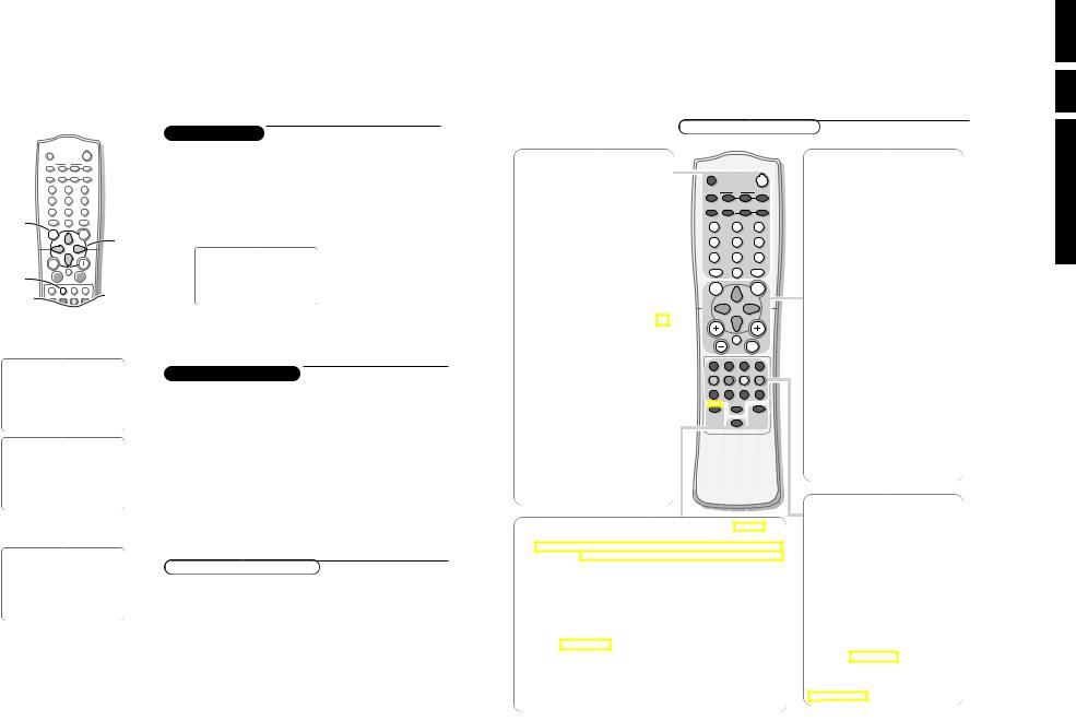
To use the menus
& Press the MENU key to display/cancel the main menu.
éUse the cursor in the up/down directions to select a menu item.
Note: Sometimes not all the menu items are visible on the screen; press the cursor down until all the items are displayed.
“Use the cursor in the left/right directions to access the sub-menu and to adjust the settings.
‘ Press the menu key to return.
( Press the i key to switch the menu off.
PICTURE
SOUND
FEATURES
INSTALL
Note: If no action is executed, the menu automatically disappears after about 12 seconds.
Store TV channels
Select the menu language
First, select your language.
& Press the MENU key.
é Select INSTALL with the cursor down.
“ Press the cursor right to select LANGUAGE.
‘ Press the cursor right again.
( Select your language with the cursor up/down.
§Press the MENU key to return to the main menu.
From now onwards, all on-screen displays will appear in the language that you have chosen.
You can now search for and store the TV channels in two different ways: using Auto store or Manual store (tuning in channel by channel).
Automatic tuning of channels
& Select AUTO STORE in the INSTALL menu.
éPress the cursor right to start the searching.
All TV channels are searched for and stored automatically.
“When the tuning is completed, press the MENU key to return to the INSTALL menu or press the i key to switch the menu off.
Note: Channel numbers will always be written in Latin characters, even when a language has been selected which uses other characters.
Preparation
Your remote control
DOLBY V ◊ |
Dolby Virtual (with Dolby Surround signals)
Dolby Virtual (Virtual Dolby Surround) enables you to experience the effect
of Dolby Pro Logic Surround, reproducing a rear sound effect.
Incredible Surround
In Stereo sound mode, when Incredible Surround is selected, it seems as though the loudspeakers are spread further apart from one another.
In Mono sound mode, this feature, when switched on, enables you to hear a spatial effect of sound.
Active Control On/Off h
Measures and corrects all incoming signals in order to provide the best picture
quality settings. Press to select the Active Control values On or Off.
ON: Sharpness and Noise Reduction are controlled automatically.The Picture settings are being adapted continuously and automatically. The menu items cannot be selected.
PROGRAM LIST î
Allows you to navigate through a list of installed programmes for a quick overview of the channels and activate the channel you have selected.
MENU Displays main menu.
Also exits the menu from the screen or returns to a higher menu level.
SURF
Allows you to select up to a maximum of 10 favourite channels or sources and view quickly the selected channels or sources.
To add a new channel or source:
•Select the channel number or source you want to add to the surf list.
•Press the SURF key.
The request ADD? appears next to the selected channel number or source.
•Press the cursor right to add.
To delete a channel or source:
•Select the channel number or source you want to remove from the surf list.
•Press the SURF key.
The request DELETE? appears next to the selected channel number or source.
•Press the cursor right to delete.
Press the SURF key repeatedly to scroll through the selected channels or sources.
Cursor
Up/Down: allows you to select the next or previous item on the menu and to select another picture format
Left/Right: allows you to access the sub-menus and adjust the settings.
V Volume +/-
Increases or decreases volume.
¬Mute
Mutes the sound.To restore the sound, press the button again.
CH +/- Selects channels in ascending or descending order.
AV Allows you to select the AV channels.
i On Screen Display
•Displays the channel number, sound transmission mode, the clock and the status of the sleeptimer.
•Also allows you to exit menu from screen.
X
Allows you to switch from Stereo to Mono sound during stereo transmission or to choose between Language Y or Language Z during dual sound transmission.
C Timer
Allows you to set the clock to switch to another channel at a specified time while you are watching another channel or when the set is on standby mode.
Colour keys,bhUf Teletext
(if provided) See p. 13
Allows you to access teletext information.
g
 for future use
use for Directions .3
.3 6 GB
EM1A
use for Directions
4 Installation

INSTALL LANGUAGE AUTO STORE MANUAL STORE SORT CHANNEL EDIT NAME
MANUAL STORE COLOUR SYSTEM SOUND SYSTEM SEARCH CHANNEL
STORE/STORED
FINE TUNE
PLL
Manual tuning of channels
Manual tuning allows you to store channel by channel.
You must go through every step of the manual store menu.
& Select MANUAL STORE in the INSTALL menu.
é Press the cursor right to enter the menu.
“Select COLOUR SYSTEM and press the cursor right.
If AUTO is selected, the respective colour system will be automatically selected according to the transmission system.
If the reception is poor, select another colour system with the cursor up/down.
‘ Press the MENU key or the cursor left.
(Select SOUND SYSTEM and press the cursor right.
If AUTO is selected, the respective sound system will be automatically selected according to the transmission system.
Note: If the reception is poor, select another sound system with the cursor up/down.
§ Press the MENU key or the cursor left.
èSelect SEARCH and press the cursor left or right to start the searching. Searching stops once a transmitting channel is found.
Note: If the reception is poor, select another colour and/or sound system.
! Select CHANNEL.
çKey in the desired channel number with the digit keys or with the cursor left/right.
0Press the cursor down.
In case of poor reception, you can improve the reception by adjusting the
frequency.
1 Select FINE TUNE and press the cursor left/right to adjust.
2In rare cases certain TV channels may reproduce distorted or unstable pictures.
Select PLL (Phase Locked Loop) to switch to the setting 2 with the cursor left/right to restore the picture for the respective transmission.
3 Press the cursor down to select STORE.
4Press the cursor right.
The message STORED appears and the search menu item is highlighted again.
5Now repeat steps èto 4to continue searching for another transmitting channel.
6Press the MENU key to return to the INSTALL menu or press the i key to switch menu off.
Installation 5
INSTALL
LANGUAGE
AUTO STORE
MANUAL STORE
SORT
CHANNEL EDIT
NAME
SORT FROM TO
EXCHANGE/EXCHANGED
INSTALL LANGUAGE AUTO STORE MANUAL STORE SORT
CHANNEL EDIT ƒ NAME
INSTALL
LANGUAGE
AUTO STORE
MANUAL STORE
SORT
CHANNEL EDIT
NAME
3
4
5
6
7 SKIPPED
CNN
6 Installation
Sorting of channels
According to your preference you can change the order of the stored TV channels.
& Select SORT in the INSTALL menu.
é Press the cursor right to enter the menu.
“Key in the channel number in the FROM column you want to swap from. Use the digit keys or the cursor left/right.
‘ Press the cursor down and select TO.
( Key in the channel number in the TO column you want to swap to.
§ Press the cursor down and select EXCHANGE.
èPress the cursor right.
The message EXCHANGED appears and the selected channels are exchanged.
! Repeat steps “to èuntil all TV channel are allocated as you like.
çPress the MENU key to return to the INSTALL menu or press the i key to switch menu off.
Editing of channels
to edit or skip channels from the channel list which or channels which you do not watch often.
skipped, you cannot select it with the CH - or + key. channel with the digit keys.
in the INSTALL menu.
enter the channel list.
want to skip with the cursor up/down.
skip the selected channel. is displayed.
to select another channel and repeat step ‘.
the MENU key to return to the install menu or the off.
to the list, repeat steps &to ‘ and press the off.
Naming of channels
to a TV channel.This feature allows you to an existing name of a channel, including
selected another language in the language menu, only set is offered to enter names to the TV channels
you want to assign a name or modify the
menu.
enter the menu.
with the cursor up/down.
with the cursor right and key in the next to a maximum of 5 characters.
the named channel.
use for Directions
EM1A
7 GB .3
Connect Peripheral Equipment
CABLE
75
Monitor |
AV 1 |
AV 2 |
in |
||
|
|
S-VIDEO |
3 |
VIDEO INPUT |
|
OUT
j x
There is a wide range of audio and video equipment that can be connected to your TV.The following connection diagrams show you how to connect them.
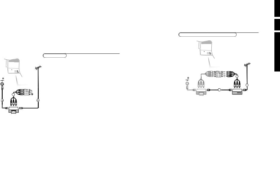
Video recorder
& Connect the RF cable 1 to the RF socket x of your video recorder.
éConnect another RF cable 2 from the output j of your video recorder to the input x of your TV.
Better playback quality can be obtained if you also connect the Video, Audio Left and Right (only for stereo equipment) cables 3 to the VIDEO,
AUDIO L/Mono and R input AV2 IN.
Note: in case of mono equipment, only the left loudspeaker reproduces sound. Use a mono to stereo adaptor (not supplied) for sound reproduction via all internal loudspeakers.
The MONITOR OUT connectors can be used for daisy chaining or to record programmes from your TV. See Record with your video recorder, p. 18.
S-VHS-Video quality with a S-VHS video recorder is obtained by connecting the S-VHS-Video cable with the S-VIDEO input instead of connecting the video recorder to the VIDEO input. (See the instructions of your video recorder.)
If the cables 3 are not used the following steps are required:
VCR
Search for and store the test signal of the video recorder
& Unplug the RF cable 1 from the RF socket x of your video recorder.
éSwitch on your TV and put the video recorder on the test signal or play a prerecorded tape (See the handbook for your video recorder.).
“Search for the test signal of your video recorder in the same way as you searched for and stored the TV signals. See Installation, Store TV Channels, Manual Tuning, p. 5.
‘ Store the test signal under programme number 0 or between 90 and 99.
(Replace the RF cable in the RF socket x of your video recorder after you have stored the test signal.
Video recorder and other A/V peripherals
CABLE
4
OUT 1
IN
& Interconnect your video recorder with extra RF cables 3.
éTo obtain better picture quality, also connect the Video, Audio left and Audio right (only for stereo equipment) cables to the VIDEO, AUDIO L/Mono and AUDIO R input of AV2 IN sockets 4.
Note: in case of mono equipment, only the left loudspeaker reproduces sound. Use a mono to stereo adaptor (not supplied) for sound reproduction via all internal loudspeakers.
When a video recorder is not connected to MONITOR OUT you can only record a programme from the aerial or from the cable system.
Only when a video recorder is connected to MONITOR OUT it is possible to record a programme from other equipment connected to the TV. See Record with your video recorder, p. 18.
.3 8 GB
EM1A
use for Directions
Connect Peripheral Equipment 15 |
16 Connect Peripheral |

S•VIDEO 
VIDEO
AUDIO
1
2 3
Monitor |
AV 1 |
AV 2 |
|
in |
|
|
Y |
|
|
Pb |
|
|
Pr |
|
COMPONENT VIDEO INPUT |
|
|
1 |
|
2 |
DVD
L 

Camera & camcorder
& Connect your camera or camcorder to sockets at the right side of your TV.
éConnect the equipment to VIDEO 2 and AUDIO L 1 for mono equipment.
“For stereo equipment also connect AUDIO R 1.
S-VHS quality with an S-VHS camcorder is obtained by connecting the S-VHS cables with the S-VIDEO input 3 (instead of VIDEO 2) and AUDIO inputs 1.
DVD-player
&Connect the cables of your Y-Pb-Pr DVD player 1 to the Y-Pb-Pr input AV1 in sockets on the TV.
For correct picture reproduction also connect to VIDEO. (See the handbook of your DVD player.)
éConnect the Audio left and right (only for stereo equipment) cables to the AUDIO L/Mono and R input.
Headphone
& Insert the plug into the headphone socket L at the right side of the TV.
éPress ¬ on the remote control to switch off the internal loudspeakers of the TV.
The headphone impedance must be between 8 and 4000 Ohm. The headphone socket has a 3.5 mm jack.
In the SOUND menu select Headphone to adjust the headphone volume and balance.
Connect Peripheral Equipment 17
D |
|
|
B |
|
|
P I P |
S |
A/CH |
æ |
ß |
ê |
|
|
|
PIP CH |
q |
© |
UP |
DN |
1 |
|
2 |
3 |
4 |
|
5 |
6 |
7 |
|
8 |
9 |
SMART |
|
0 |
SMART |
M |
|
a |
|
|
|
|
|
MENU |
|
|
SURF |
V |
|
¬ |
CH |
AV |
i |
X |
C |
AV |
|||
b |
h |
g |
U |
DOLBY V. |
|
|
PROGRAM LIST |
◊ |
|
f |
|
ACTIVE CONTROL h
18 Record
To select connected equipment
cable only :
you have stored the test signal with
or to the right side of the TV
, CVI, AV2 or FRONT, according to the back or the right side of your
discs if you used the Component L/Mono and R inputs).
which you want to watch with
Record with your video recorder
directly to the video
.
recording !
connected to connected to
of the TV
your video recorder.
.
off your TV when you are recording !
use for Directions
EM1A
9 GB .3

Before Calling Service
Please make these simple checks before calling service.These tips may save you time and money since charges for television installation and adjustments of customer controls are not covered under your warranty.
Symptoms |
Items to Check and Actions to follow |
||
|
|
|
|
“Ghost” or double images |
• |
This may be caused by obstruction to the antenna due to high rise buildings or hills. |
|
|
|
Using a highly directional antenna may improve the picture. |
|
|
|
|
|
No power |
• |
Check that the television's AC power cord is plugged into the mains socket. |
|
|
• Unplug the television, wait for 60 seconds. |
||
|
|
Then re-insert the plug into the mains socket and turn on the television again. |
|
|
|
|
|
No picture |
• |
Check the antenna connection at the rear of the television to see if it is properly connected to the |
|
|
|
television input terminal. |
|
|
• Possible broadcast station trouble. Try another channel. |
||
|
• Adjust the contrast and brightness settings or select another picture setting with the smart picture key. |
||
|
|
|
|
Good picture but no sound |
• |
Increase the VOLUME. |
|
|
• |
Check that the television is not muted, press the ¬ button on the remote control. |
|
|
• When no signal is detected, the television automatically switches off the sound. |
||
|
|
This is proper operation and does not indicate a malfunction. |
|
|
• Check the transmission system’s sound settings of this set. |
||
|
|
|
|
Good sound but poor |
• |
Adjust the contrast and brightness setting or select another picture setting with the smart picture key. |
|
colour or no picture |
• |
Check the transmission system’s colour settings of this set. |
|
|
|
|
|
Poor picture |
• |
Sometimes, poor picture quality occurs when having activated an S-VHS camera or camcorder |
|
|
|
connected to the right side of of your TV and another peripheral is connected to AV1 or AV2 at the |
|
|
|
same time. In this case, switch off one of the other peripherals. |
|
|
|
|
|
Snowish picture and noise |
• |
Check the antenna connection. |
|
|
|
|
|
Horizontal dotted line |
• |
This may be caused by electrical interference (e.g. hairdryer, nearby neon lights, etc.) |
|
|
• Turn off the equipment. |
||
|
|
|
|
One white line across the |
• |
Turn off the television immediately and consult a qualified service personnel. |
|
screen |
|
|
|
|
|
||
Television not responding to |
• Check whether the batteries are working. Replace if necessary. |
||
• Clean the remote control sensor lens on the television. |
|||
remote control |
|||
• Operating range between television and the remote control should not be more than 6 meters. |
|||
|
|||
|
• |
You can still use the keys at the top of your TV. |
|
|
|
||
NICAM sound distortion |
• This could be due to antenna siting or reflected signal. |
||
• Switch over to “MONO” mode by pressing the X key. |
|||
(crackling noise) |
|||
|
|
||
|
|
||
Wrong menu |
• Press the i key again to exit from the menu. |
||
|
|
||
|
|
|
|
If your problem is not solved
Turn your TV off and then on again once.
Never attempt to repair a defective TV yourself.
Check with your dealer or call a TV technician.
Personal notes:
.3 10 GB
EM1A
use for Directions
Before Calling Service 19
Mechanical instructions |
EM1A |
|
4. |
|
GB 11 |
4. Mechanical instructions
4.1Removing the Rear Cover
1.Remove all the fixation screws of the rear cover.
2.Now the rear cover can be removed by pulling it backward.
4.2Service positions
4.2.1Service position LSP
Position 1: For better accessibility of the LSP, do the following:
SSB
LSP
 LSP - bracket
|
|
3 |
1 |
4 |
|
|
Bottom tray |
|
|
|
|
|
2 |
|
1 |
|
|
|
|
|
|
|
2 |
CL 06532130_004.eps
031000
Figure 4-1
1.Remove the LSP-module from the bottom tray by pulling the complete module backand then upward.
2.Hook the bracket in the first row of fixation holes of the cabinet bottom. In other words reposition the bracket from [1] to [2].
3.The same can be done with the DW-module (position [3] to [4]).
Position 2: This service position is comparable to that of the A10A. To get access to the bottom side (solder side) of the LSP, do the following:
1
2
A
|
3 |
|
4 |
B |
CL 06532130_006.eps |
121000 |
Figure 4-2
1.Disconnect the CRT/SCAVEM panel from the CRTsocket.
2.Release LSP and DW-module, and pull backward.
3.Remove Mains switch module from bottomplate (see description below).
4.Free the necessary wiring from their fixation clamps, for the ease of handling.
5.Sometimes a cable must be disconnected for the ease of handling, like the degaussing coil (0020) and loudspeaker (1735, 1736 & 1737) cables.
6.Now reposition following modules, in order to cope with the LSP service position:
–DAF-module from the LSP-bracket by pressing lever while pushing the module forward in the direction of the CRT (see also description below).
–Mains Harmonic module from the LSP-bracket by removing 1 screw and then slide the module backward, away from the CRT (see also description below).
7.Turn the chassis tray 90 degrees counter clockwise (see figure 4.2 - [2]).
8.Flip the chassis tray with the rear I/O panel towards the CRT [3].
9.Place the hook of the tray in the fixation hole at the right side of the cabinet bottom and pull the chassis tray backward [4].

GB 12 |
|
4. |
|
EM1A |
Mechanical instructions |
10.Reconnect cables (except degaussing cable 0020), panels and modules.
Alternative position 2: A somewhat easier way to access the bottom side (solder side) of the LSP is the following (only possible when the high tension cable is long enough):
2
 1
1
1 
|
3 |
A |
CL 06532130_007.eps |
131000 |
Figure 4-3
1.Disconnect the CRT/SCAVEM panel from the CRTsocket.
2.Release LSP and DW-module, and pull backward.
3.Remove Mains switch module from bottomplate (see description below).
4.Free the necessary wiring from their fixation clamps, for the ease of handling.
5.Sometimes a cable must be disconnected for the ease of handling, like the degaussing coil (0020), loudspeaker (1735, 1736 & 1737) cables and 0325 (frame deflection).
6.Now reposition following modules, in order to cope with the LSP service position:
–DAF-module from the LSP-bracket by pressing lever while pushing the module forward in the direction of the CRT (see also description below).
–Mains Harmonic module from the LSP-bracket by removing 1 screw and then slide the module backward, away from the CRT (see also description below).
7.Flip the chassis tray 90 degrees clockwise [2].
8.Place the hook of the tray in fixation hole [A] of the cabinet bottom and pull the chassis tray backward [3].
9.Reconnect the cables (except degaussing cable 0020), panels and modules.
4.2.2Service position SSB
All relevant test points can be accessed with the SSB in original position, but for ease of use a 'SSB extension board' is available under number 9965 000 05769.
Before usage of this board, the 'LSP top-bracket' has to be taken out. This can be done by:
1.Remove the DAF panel (see 4.2.5).
2.Remove the 2 screws which hold the bracket at the right side.
3.Lift the bracket at the same side. It hinges at the cooling plate.
Note: For some type numbers, the LSP has to be moved slightly to the right side in order to create enough space for the SSB extension board.
To get access to the test points of the SSB, the shielding has to be removed:
|
|
|
2 |
|
|
|
|
|
3 |
|
|
|
|
5 |
|
|
1 |
|
1 |
|
|
|
|
|
PIP/DW FROM |
|
|
0948 |
|
MODULE |
(0205) |
|
0946 |
|
|
|
|
|
|
4 |
|
|
|
|
 4
4
CL 06532130_008.eps
131000
Figure 4-4
1.Put the LSP in service position 1 (as described above).
2.If a PIP/DW module is present, then disconnect the IFcable from connector 1946, flatcable from connector 1948 and flatfoil on DW-module connector 0205 [1].
3.Release the 'top fixation clamp' which holds the SSB [2] and pull the SSB slightly towards the Tuner [3]. At the same time, the 2 metal clamps at both sides of the SIMMconnector must be released [4] . The complete SSB can be taken out now by pulling the topside of the SSB towards the Tuner [5]. It 'hinges' in the SIM-connector.
2 1 

 1
1
CL 06532130_009.eps
031000
Figure 4-5
1.Once the SSB has been taken out of the connector, the shielding can be removed.
2.After removal of the shielding, the panel can be replaced in its connector in reverse order. Don't forget to reconnect the cables.
3.If necessary for the measurement, the LSP can be put in
'service position 2' (as described above).

Mechanical instructions |
EM1A |
|
4. |
|
GB 13 |
4.2.3Accessing the Double Window (DW) panel
PIP/Double Window 1
Multi Voltage
1 
4
2
3
4
CL 06532130_015.eps
031000
Figure 4-6
1.Remove the DW bracket from the bottom tray by pulling it backward (after pressing the fixation clamp).
2.The board can easily be lifted out of the bracket [2] after releasing the 2 fixation clamps [1].
4.2.4Accessing the Multi Voltage panel (if present)
1.Remove the DW bracket from the bottom tray by pulling it backward.
2.Press the 2 fixation clamps downward [3] (see figure 4- 7).
3.The board can easily be lifted out of the bracket after releasing the 2 fixation clamps [4].
4.2.5Accessing the Double Astigmatic Focus (DAF) panel
3
|
3 |
3 |
2 |
|
1.The complete module can be removed from the LSPbracket by pressing its fixation clamp [1] (located behind the PWB), while sliding the module in the direction of the CRT [2].
2.The board can easily be lifted from its bracket after releasing the 2 fixation clamps [3].
4.2.6Accessing the Mains Harmonic panel
1 3
2
 3 3
3 3
CL 06532130_017.eps
131000
Figure 4-8
1.The complete module can be removed from the LSPbracket (after removal of the DAF-panel) by removing screw [1] and then slide the module in the opposite direction of the CRT [2].
2.The board can easily be lifted from its bracket after releasing the 2 fixation clamps [3].
4.2.7Accessing the Top Control panel
M
Top control board
CL 06532012_003.eps
030200
Figure 4-9
1.Remove the two fixation screws, which hold the panel.
2.Pull the board backward (w.o.w. release it from its front hinge [M]).
3.The board can easily be lifted from its bracket after releasing the 2 fixation clamps at the connector side.
1
CL 06532130_016.eps
031000
Figure 4-7

GB 14 |
|
4. |
|
EM1A |
Mechanical instructions |
|
4.2.8 Accessing the Side I/O panel |
1. |
The complete Side I/O-assembly can easily be removed |
||||
|
|
|
|
|
|
by unscrewing the 2 fixation screws. |
|
|
|
|
|
2. |
The board can easily be lifted out of the bracket after |
|
|
|
|
|
|
releasing the 2 fixation clamps. |
CL 06532012_004.eps
030200
Figure 4-10
4.2.9Accessing the Mains Switch panel
1 


1
2
3 
 3
3
CL 06532130_018.eps 021000
Figure 4-11
The easiest way to access this module is with the LSP in service position 2.
1.Release the two fixation clamps by pulling them backward [1].
2.At the same time, the complete assy must be pulled backward [2].
3.If the board has to be removed, release the 2 clamps at the bracket sides and lift panel up [3].
4.3Mounting the Rear Cover
Before mounting the Rear Cover, some checks has to be performed:
•Check whether the Mains Cord is mounted correctly in the guiding brackets.
•Check whether all cables are replaced in their original position. This is very important due to the large 'hot' area of the set.

Fault finding and repair tips |
EM1A |
|
5. |
|
GB 15 |
5. Fault finding and repair tips
In this chapter the following paragraphs are included:
1.Test points.
2.Service Modes.
3.Problems and solving tips (related to CSM).
4.ComPair.
5.Error codes.
6.The 'blinking LED' procedure.
7.Protections.
8.Repair tips.
5.1Test points
The EM1A chassis is equipped with test points in the service printing. These test points are referring to the functional blocks:
•A1-A2-A3, etc.: Test points for the audio processing circuitry [A5, A6, and B6].
•C1-C2-C3, etc.: Test points for the control circuitry [B7].
•F1-F2-F3, etc.: Test points for the frame drive and frame output circuitry [A4, B4] and Double Window [C].
•F1F-F2F, etc.: Test points for the RGB-signals on the CRT panel [F].
•I1-I2-I3, etc.: Test points for the intermediate frequency circuitry [A7, B2].
•L1-L2-L3, etc.: Test points for the line drive and line output circuitry [A3, B4].
•P1-P2-P3, etc.: Test points for the power supply [A1, A2].
•SC1-SC2, etc.: Test points for the synchronisation circuitry on the CRT panel [F].
•V1-V2-V3, etc.: Test points for the video processing circuitry [B].
The numbering is done, in a for diagnostics logical sequence; always start diagnosing within a functional block in the sequence of the relevant test points for that functional block.
Measurements are performed under the following conditions:
•Service mode: SDM.
•Video: colour bar signal.
•Audio: 3 kHz left, 1 kHz right.
•Via grounding the 'Front Detect'-line on the Side I/O panel during switch ON (pins 1 and 7 of connector 0936).
•By the 'DEFAULT' button on the DST while the set is in the normal operation mode.
CAUTION: Entering SDM by grounding the 'Front Detect'- line will override the 5V-protection. This should only be done for a short period of time. In case of SW-protections (errors 1 - 4), the set will shutdown in 15 s.
When doing this, the service-engineer must know what he is doing as it could lead to damaging the set.
After entering SDM, the following screen will be shown with 'SDM' at the upper right side for recognition.
SDM Menu
S D M
H R S : 0 0 0 1 S W I D : E M 1 1 A 1 - 1 . 0
E R R : 0 0 0 0 0 0 0
|
|
|
S D M |
|
|
P I C T U R E |
B R I G H T N E S S |
i + |
|
S O U N D |
C O L O U R |
MENU |
F E A T U R E S |
C O N T R A S T |
|
|
|
I N S T A L L |
S H A R P N E S S |
|
|
|
C O L O U R T E M P |
|
S D M |
|
|
CL 06532130_010.eps
031000
Figure 5-1
Explanation
Access to normal user menu
Pressing the 'MENU' button on the remote control, switches between the SDM and the normal user menus (with the SDM mode still active in the background).
Error buffer
Pressing the 'OSD' button [i+] of the remote control, shows / hides the error buffer. OSD can be hidden to prevent interference with oscillogram measurements.
5.2Service modes
5.2.1Service Default Mode (SDM)
Purpose
•To provide a situation with predefined settings to get the same measurement results as given in this manual.
•Start the 'Blinking LED' procedure.
•Have the possibility to override the 5V-protection.
Specification
•Tuning frequency 475.25 MHz for PAL/SECAM sets and at channel 3 (61.25 MHz) for NTSC-sets.
•All picture settings at 50 % (brightness, colour, contrast, hue).
•All sound settings at 50 % except volume at 25 % (so bass, treble, balance at 50 %, volume at 25 %).
•All service-unfriendly modes are disabled, like timer, sleep timer, parental lock, blue mute, hospitality mode and no-ident timer (normally the set is automatically switched off when no video signal - IDENT - was received for 15 minutes).
Entering
•Via a standard RC-handset by entering the code '062596' followed by the 'MENU' button.
•Via ComPair.
Access to SAM
By pressing the 'VOLUME +' and 'VOLUME -' buttons on the local keyboard simultaneously for a few seconds, the set toggles from SDM to SAM.
Exiting
There are 2 ways to exit this mode:
•Switch the set to 'STANDBY', the error buffer will also be cleared (by switching the set OFF-ON with the mains switch, the set will come up again in the SDM).
•By pressing the 'EXIT' button on the DST.
5.2.2Service Alignment Mode (SAM)
Purpose
•To perform alignments.
•To change option settings.
•To display / clear the error code buffer.
Specification
•Software alignments (see chapter 8).
•Option settings (see chapter 8).
•Error buffer reading and erasing. The most recent error code is displayed on the left side.
•Operation counter.
•Software version.

GB 16 |
5. |
|
EM1A |
Fault finding and repair tips |
|
|
||
Entering |
|
|
|
• By the 'ALIGN' button on the DST while the set is in the |
||||
• Via a standard RC-handset by entering the code |
|
normal operation mode. |
||||||
|
'062596' followed by the 'OSD' button [i+]. |
The following screen will be shown, with 'SAM' at the upper |
||||||
• |
Via ComPair. |
|
|
right side for recognition. |
||||
SAM Menu |
|
|
|
|
|
|
||
|
|
|
|
S A M |
|
N P R G |
S A M |
|
P I C T U R E |
|
B R I G H T N E S S |
|
|
||||
S O U N D |
|
C O L O U R |
|
MENU |
W S S B |
|
||
F E A T U R E S |
C O N T R A S T |
|
|
S Y S T E M |
|
|||
I N S T A L L |
|
S H A R P N E S S |
|
|
O B 1 |
|
||
|
|
|
C O L O U R T E M P |
|
O B 2 |
|
||
1 |
|
MENU |
2 |
3 |
4 |
|
|
|
H R S : 0 0 0 3 S W I D : E M 1 1 A 1 - 1 . 0 |
S A M |
|
S A M |
|||||
|
|
|
|
|
|
T U N E R |
|
|
E R R : 0 0 0 0 0 0 0 |
|
MENU |
|
|
||||
O P T : 2 5 4 1 0 0 1 2 8 0 0 0 0 0 |
I F - P L L O F F S E T |
|||||||
|
||||||||
|
|
|
|
|
|
A G C |
|
|
C L E A R E R R O R S |
|
|
2 N D |
|
||||
O P T I O N S |
|
|
|
|
|
|||
A K B O N / O F F |
|
|
A F A |
|
||||
O P C O N / O F F |
|
|
A F B |
|
||||
V S D O N / O F F |
|
|
|
|
||||
T U N E R |
|
|
|
|
|
|
||
W H I T E |
T O N E |
|
MENU |
|
||||
G E O M E T R Y |
|
|
|
|
S A M |
|||
S O U N D |
|
|
|
|
|
|||
|
|
|
|
N O R M A L |
R E D |
|||
|
|
|
|
|
|
|||
5 |
|
|
|
|
|
|
|
|
|
|
|
|
|
|
|
S A M |
|
|
|
|
|
|
|
V E R - S L O P E |
||
|
|
|
|
|
MENU |
|
|
|
|
|
|
|
|
|
|
S A M |
|
|
|
|
|
|
MENU |
S O U N D |
|
|
|
|
|
|
|
|
|
||
|
|
|
|
|
|
N I C - F M A M |
||
|
|
|
|
|
|
2 C S - F M |
|
|
|
|
|
|
|
|
P S - F M |
|
|
|
|
|
|
|
|
P S - N I C - B G D K |
||
|
|
|
|
|
|
P S - N I C - I |
||
|
|
|
|
|
|
|
CL 06532130_011.eps |
|
|
|
|
|
|
|
|
021000 |
|
Figure 5-2
Explanation
The Service Alignment Mode menu will now appear on the screen. The following information is displayed:
1.Operation hours timer (hexadecimal).
2.Software identification of the main micro controller (AAABBB-X.Y).
•AAA is the chassis name (EM1= Painter processor, EM2= OTC processor).
•B = Software code belonging to a certain stroke number (see table below).
•X = (main version number).
•Y = (subversion number).
3.Error buffer (7 errors possible).
4.Option bytes (8 codes possible), summary of options are explained below.
5. Sub menus are listed in a scroll-menu.
Country |
Strokenumber |
Software |
|
|
|
Singapore |
/69 |
2A1 |
|
|
|
Thailand |
|
|
|
|
|
Malaysia |
|
|
|
|
|
Indonesia |
|
|
|
|
|
Middle East |
/56 |
2A2 |
|
|
|
China |
/93 |
1A1 |
|
|
|
Hong Kong |
/57 |
2A1 |
|
|
|
Australia |
/79 |
|
|
|
|
New Zealand |
|
|
|
|
|

Fault finding and repair tips |
EM1A |
|
5. |
|
GB 17 |
Menu control
Menu items can be selected with the 'CURSOR UP/DOWN' key. The selected item will be highlighted. When not all menu items fit on the screen, moving the 'CURSOR UP/DOWN' will display the next/previous menu items.
With the 'CURSOR LEFT/RIGHT' keys, it is possible to:
•(De)activate the selected menu item (e.g. GEOMETRY).
•Change the value of the selected menu item (e.g. VERSLOPE).
•Activate the selected submenu (e.g. SERV-BLK).
Access to normal user menu
Pressing the 'MENU' button on the remote control switches between the SDM and the normal user menus (with the SAM mode still active in the background). Pressing the 'MENU' key in a submenu will go to the previous menu.
The menus and submenus
•CLEAR ERRORS. Erasing the contents of the error buffer. Select the CLEAR ERRORS menu item and press the 'CURSOR RIGHT' key. The content of the error buffer is cleared.
•The functionality of the OPTIONS and ALIGNMENTS (TUNER, WHITE TONE, SOUND, GEOMETRY and SMART SETTING) sub menus is described in chapter 8.
Exiting
There are 2 ways to exit this mode:
•Switch the set to 'STANDBY', the error buffer will also be cleared (by switching the set OFF-ON with the mains switch, the set will come up again in the SAM).
•By pressing the 'EXIT' button on the DST.
5.2.3Customer Service Mode (CSM)
Purpose
The 'Customer Service Mode' is a special service mode, which can be activated and deactivated by the customer upon request of the service technician/dealer during a telephone conversation, in order to identify the status of the set. This CSM is a 'read only' mode, therefore modifications in this mode are not possible.
Entering
The Customer Service Mode will switch ON after pressing the 'MUTE' key on the remote control handset and any of the top control buttons on the TV for at least 4 seconds simultaneously. This activation only works if there is no menu on the screen.
Explanation
After switching on the Customer Service Menu the following screen will appear:
CSM Menu
|
|
|
|
|
C S M |
1 |
H R S : |
0 0 0 5 S W I D : E M 1 1 A 1 - 1 . 0 |
|
||
2 |
C O D E S : 0 0 0 0 0 0 0 |
|
|
||
3 |
O P T : |
2 5 4 1 0 0 1 2 8 0 0 0 0 0 |
|
||
4 |
S Y S T E M : A U T O |
1 1 |
S O U N D : M O N O |
||
5 |
N O S I G N A L |
1 2 |
V O L U M E : |
|
|
6 |
T I M E R O N |
1 3 |
B A L A N C E : + / - |
||
7 |
C H A N N E L B L O C K E D |
1 4 |
H U E : |
+ / - |
|
8 |
N O T P R E F E R R E D |
1 5 |
C O L O U R : |
|
|
9 |
H O T E L M O D E O N |
1 6 |
B R I G H T N E S S : |
||
1 0 S O U R C E : 1 |
1 7 |
C O N T R A S T : |
|
||
CL 06532130_012.eps
131000
Figure 5-3
Line 1:
HRS: Hexadecimal counter of operating hours (example: 1B (hex) = 0001 1011 (bin) = 27 (dec)). Standby hours are not counted as operating hours.
SWID: Software identification of the main micro controller (see paragraph 5.2.2). Details on available software versions can be found in the chapter 'Software Survey' of the publication 'Product Survey - Colour Television'.
Line 2:
Error code buffer (for more details see paragraph 5.3). Displays the last 7 errors of the error code buffer.
Line 3:
Software and hardware functionality of the EM1A is controlled by option bits. An option byte or option number represents 8 of those bits. Each option number is displayed as a decimal number between 0 and 255. The set may not work correctly when an incorrect option code is set. See chapter 8 for more information on correct option settings
Line 4:
Indicates which colour and sound system is installed for the selected pre-set:
Line 5:
Indicates that the set is not receiving an 'ident' signal on the selected source.
Note: On some models, BLUE MUTE is displayed (if the BM option is ON) when no signal is received.
Line 6:
Indicates whether the SLEEPTIMER function is ON/OFF.
Line 7:
Indicates whether the CHILD LOCK function is ON/OFF.
Line 8:
Indicates whether the current pre-set is defined as SKIPPED or NON-PREFERRED.
Line 9:
Indicates whether the HOTEL MODE is activated.
Line 10:
Indicates which SOURCE is installed for this pre-set: EXT1, SVHS2, EXT2, and Tuner.
Line 11:
Indicates which sound mode is installed for this pre-set: Mono, NICAM, Stereo, L1, L2, SAP or Virtual
Line 12 to 17:
Value indicates parameter levels at CSM entry.
Exiting
The Customer Service Mode will switch OFF after pressing any key of the remote control handset (with exception of the 'P+' and 'P-' keys) and switching OFF the TV set with the mains switch.
5.3Problems and solving tips (related to CSM)
5.3.1Picture problems
No colours / noise in picture
Check CSM line 4. Wrong colour system installed. To change the setting:
1.Press the 'MENU' button on the remote control.
2.Select the INSTALL sub menu.
3.Select the MANUAL STORE sub menu.
4.Select and change the COLOUR SYSTEM setting until picture and sound are correct.
5.Select the STORE menu item.
 Loading...