


Colour television |
Chassis |
EM2E
AA
CL 96532156_000.eps
080200
|
|
|
|
|
|
|
Contents |
|
Page |
Contents |
Page |
||
1 |
Technical specifications, connection facilities |
2 |
8 |
Electrical alignments |
71 |
|
|
and chassis overview |
|
|
9 |
Circuit Descriptions |
76 |
2 |
Safety instructions, maintenance, |
|
4 |
|
List of abbreviations |
92 |
|
warnings and notes |
|
|
10 |
Spare parts list |
94 |
3 |
Directions for use |
|
5 |
|
|
|
4 |
Mechanical instructions |
|
17 |
|
|
|
5 |
Service modes, error codes, |
|
19 |
|
|
|
|
faultfinding and repair tips. |
|
|
|
|
|
6 |
Block diagrams |
|
|
|
|
|
|
Block diagram (Supply, Deflection) |
33 |
|
|
|
|
|
Block diagram (Video, Audio, Control) |
34 |
|
|
|
|
|
Supply lines overview |
|
35 |
|
|
|
|
Wiring diagram |
|
36 |
|
|
|
|
I2C overview |
|
36 |
|
|
|
|
Survey of testpoints |
|
37 |
|
|
|
7 Electrical Diagrams and PWB lay-outs |
Diagram PWB |
|
|
|||
|
Main supply |
(Diagram A1) |
38 |
45-50 |
|
|
|
Stand-by Supply |
(Diagram A2) |
39 |
45-50 |
|
|
|
Line deflection |
(Diagram A3) |
40 |
45-50 |
|
|
|
Frame deflection / rotation |
(Diagram A4) |
41 |
45-50 |
|
|
|
Audio amplifier |
(Diagram A5) |
42 |
45-50 |
|
|
|
Headphone amplifier |
(Diagram A6) |
43 |
45-50 |
|
|
|
Tuner, I/O, SIMM (female) |
(Diagram A7) |
44 |
45-50 |
|
|
|
Front |
(Diagram A8) |
43 |
45-50 |
|
|
|
SIMM (male) |
(Diagram B1) |
51 |
57-66 |
|
|
|
IF, I/O, Video processing (HIP) |
(Diagram B2) |
52 |
57-66 |
|
|
|
Featurebox (PICNIC) |
(Diagram B3) |
53 |
57-66 |
|
|
|
Video control & Geometry (HOP) |
(Diagram B4) |
54 |
57-66 |
|
|
|
Teletext & Control (OTC) |
(Diagram B5) |
55 |
57-66 |
|
|
|
Audio processing |
(Diagram B6) |
56 |
57-66 |
|
|
|
Mains switch panel |
(Diagram E) |
67 |
67 |
|
|
|
CRT panel |
(Diagram F) |
68 |
67 |
|
|
|
Side I/O panel |
(Diagram O) |
69 |
69 |
|
|
|
Top control |
(Diagram P) |
70 |
70 |
|
|
©Copyright reserved 2000 Philips Consumer Electronics B.V. Eindhoven, The Netherlands. All rights reserved. No part of this publication may be reproduced, stored in a retrieval system or transmitted, in any form or by any means, electronic, mechanical, photocopying, or otherwise without the prior permission of Philips.
Published by CO 0061 Service PaCE |
Printed in the Netherlands |
Subject to modification |
3122 785 10310 |
|
|
|
|
GB 2 |
|
1. |
|
EM2E |
Technical specifications, connection facilities and chassis overview |
1. Technical specifications, connection facilities and chassis overview
1.1 Technical specifications |
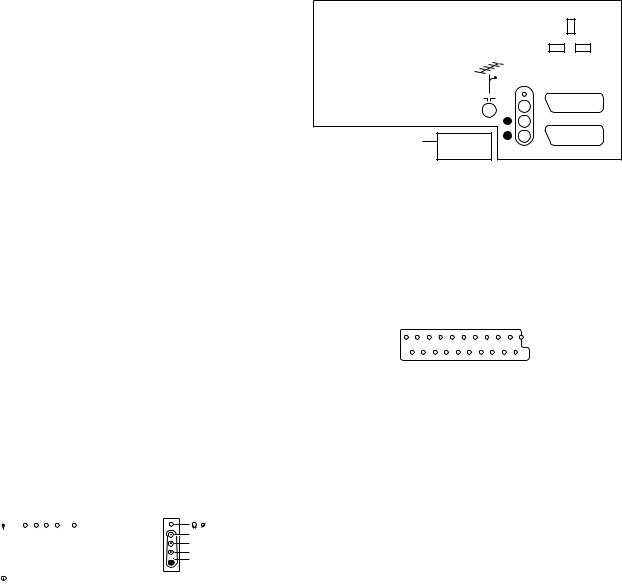
1.2.2 Rear connections |
1.1.1Reception
Tuning system |
: |
PLL |
|
|
|
|
Reception |
: |
|
|
|
|
|
TV systems off air |
: |
PAL B/G/I, SECAM B/ |
|
|
|
|
|
|
G/L/L’ for Western |
|
|
|
|
|
|
Europe |
|
|
|
|
|
: PAL B/G, SECAM B/ |
|
|
|
|
|
|
|
G/D/K, NTSC M for |
|
|
|
|
|
|
Eastern Europe |
|
|
L |
EXTERNAL 2 |
Sound systems |
: FM |
|
|
R |
|
|
|
: AM |
|
SERVICE |
|
||
|
|
|
|
|||
|
|
CONNECTOR |
AUDIO |
EXTERNAL 1 |
||
|
: |
NICAM B/G/D/K/I |
|
|||
|
|
|
||||
|
|
|
|
CL96532156_002.eps |
||
A/V connections |
: |
PAL B/G/D/K/I |
|
|
|
|
|
|
|
060199 |
|||
|
: |
SECAM B/G/D/K/L/L' |
|
|
|
|
|
|
|
|
|
||
|
: |
NTSC video playback |
|
|
Figure 1-2 |
|
Channel selections |
: |
100 channels: VHF, |
|
|
|
|
|
|
UHF, S-Channels, |
|
|
|
|
|
|
Hyperband |
Audio |
|
|
|
Frequency range |
: |
44.25 - 855.25 MHz |
- |
- Audio |
L (0.5VRMS / 10kΩ) |
|
Aerial input |
: |
Coaxial 75Ω |
- |
- Audio |
R (0.5VRMS / 10kΩ) |
|
VCR preselections |
: |
0 and 90 - 99 |
|
|
|
|
|
|
|
External 1 (in/out): RGB+CVBS |
|
||
1.1.2Miscellaneous
|
|
1 |
21 |
|
Mains voltage |
: 220V - 240V (± 10 %); |
|
|
|
|
50 - 60Hz (± 5 %) |
|
|
|
Ambient temperature |
: +5 to +45 deg. Celcius |
2 |
20 |
|
Standby Power Consumption |
: < 1W |
|||
|
CL96532137_056.eps |
|||
|
|
|
171199 |
1.2 |
Connection facilities |
|
|
|
|
|
|
Figure 1-3 |
|
||||||||
|
|
|
|
|
|
|
|
|
|
|
|
|
|
|
|
|
|
1.2.1 |
Side I/O connections |
|
|
|
|
1 |
- Audio |
R (0.5VRMS / 1kΩ) |
|
||||||||
|
|
|
|
|
|
|
|
|
|
|
|
|
|
||||
|
|
|
|
|
|
|
|
|
|
|
|
|
|
2 |
- Audio |
R (0.5VRMS / 10kΩ) |
|
|
|
|
FRONT CONTROL |
SIDE I/O |
|
3 |
- Audio |
L (0.5VRMS / 1kΩ) |
|
||||||||
|
|
|
|
4 |
- Audio |
GND |
|
||||||||||
|
|
|
|
|
|
|
|
|
|
|
|
|
|
5 |
- Blue |
GND |
|
|
|
|
|
|
|
|
|
|
|
|
|
|
|
6 |
- Audio |
L (0.5VRMS / 10kΩ) |
|
|
|
|
|
|
|
|
|
|
|
|
|
3.5 |
|
7 |
- Blue |
(0.7VPP / 75Ω) |
|
|
|
|
|
|
|
|
|
|
|
|
AUDIO R |
|
|||||
|
|
|
|
|
|
|
|
|
|
|
|
8 |
- CVBS-status |
0 - 1.3V: INT, 4.5 - 7V: EXT 16:9, 9.5 |
|
||
|
|
|
|
|
|
|
|
|
|
|
AUDIO L |
|
|
||||
|
|
|
|
|
|
|
|
|
|
|
VIDEO |
|
|
|
- 12V: EXT 4:3 |
|
|
|
|
|
|
|
|
|
|
|
|
|
|
|
|
||||
|
|
|
|
|
|
|
|
|
STANDBY LED |
|
SVHS |
|
9 |
- Green |
GND |
|
|
|
|
|
|
|
|
|
|
|
|
|
|
|
|||||
|
|
|
SK 1 |
|
IR-RECEIVER |
|
|
|
|
10 |
- |
|
|
||||
|
|
|
|
CL96532156_001.eps |
|
11 |
- Green |
(0.7VPP / 75Ω) |
|
||||||||
|
|
|
|
|
|
|
|
|
|
|
|||||||
|
|
|
|
|
|
|
|
|
|
060100 |
|
||||||
|
|
|
|
|
|
|
|
|
|
|
12 |
- |
|
|
|||
|
|
|
|
|
|
|
|
|
|
|
|
|
|
|
|
||
|
|
|
|
|
|
|
|
|
|
|
|
|
|
13Red |
GND |
|
|
|
|
|
|
|
|
|
|
|
Figure 1-1 |
|
|
|
|
14- RGB-status |
GND |
|
|
|
|
|
|
|
|
|
|
|
|
|
|
|
|
15 |
- Red |
(0.7VPP / 75Ω) |
|
|
Audio / video |
|
|
|
|
|
|
16- RGB-status |
0 - 0.4V: INT 1 - 3V: EXT / 75Ω |
|
|||||||
|
|
|
|
|
|
|
17CVBS |
GND |
|||||||||
|
- |
- Video |
|
|
|
|
|
|
|
||||||||
|
|
|
|
|
|
|
|
18CVBS |
GND |
|
|||||||
|
|
(CVBS) |
|
|
1VPP / 75Ω |
|
|
|
|
||||||||
|
|
|
|
|
|
|
19 |
- CVBS |
(1VPP / 75Ω) |
|
|||||||
|
- |
- Audio |
|
|
L (0.5VRMS / 10kΩ) |
|
|||||||||||
|
- |
- Audio |
|
|
R (0.5VRMS / 10kΩ) |
|
20 |
- CVBS |
(1VPP / 75Ω) |
|
|||||||
|
- |
- Headphone |
|
(32 - 2000Ω / 10mW) |
|
21Earth |
GND |
|
|||||||||
|
|
|
|
|
|
||||||||||||
|
SVHS |
|
|
|
|
|
|
|
|
|
|
|
|||||
|
1 - |
|
|
|
|
|
|
GND |
|
|
|
|
|
|
|
|
|
|
2 - |
|
|
|
|
|
|
GND |
|
|
|
|
|
|
|
|
|
|
3 |
- Y |
|
|
(1VPP / 75Ω) |
|
|
|
|
|
|
|
|
||||
|
4 |
- C |
|
|
(0.3VPP / 75Ω) |
|
|
|
|
|
|
|
|
||||
Technical specifications, connection facilities and chassis overview |
EM2E |
|
1. |
|
GB 3 |
External 2 (in/out): SVHS+CVBS (intended for VCR)
|
1 |
21 |
|
|
2 |
20 |
|
|
|
CL96532137_056.eps |
|
|
|
171199 |
|
|
|
Figure 1-4 |
|
1 |
- Audio |
R (0.5VRMS / 1kΩ) |
|
2 |
- Audio |
R (0.5VRMS / 10kΩ) |
|
3 |
- Audio |
L (0.5VRMS / 1kΩ) |
|
4 |
- Audio |
GND |
|
5 |
- |
GND |
|
6 |
- Audio |
L (0.5VRMS / 10kΩ) |
|
7 |
- |
|
|
8 |
- CVBS-status |
0 - 1.3V: INT, 4.5 - 7V: EXT 16:9, 9.5 |
|
|
|
- 12V: EXT 4:3 |
|
9 |
- |
GND |
|
10 |
- |
Easy link |
|
11-
12-
13Red |
GND |
|
|
14- RGB-status |
GND |
|
|
15 |
- C |
(0.7VPP / 75Ω) |
|
16 |
- |
|
|
17CVBS |
GND |
|
|
18CVBS |
GND |
|
|
19CVBS |
(1VPP / 75Ω) |
|
|
20- Y/CVBS |
(1VPP / 75Ω) |
|
|
21Earth |
GND |
|
|
1.3Chassis overview
F  P68
P68
O  P69
P69
B  P51
P51
TOP CONTROL PANEL
CRT/SCAVEM PANEL
SIDE I/O PANEL
SMALL SIGNAL BOARD
MAINSWITCH PANEL
LARGE SIGNAL PANEL
P  P70
P70
E  P67
P67
A  P38
P38
CL 96532156_004.eps
290200
Figure 1-5

GB 4 |
|
2. |
|
EM2E |
Safety & Maintenance instructions, Warnings and Notes |
2. Safety & Maintenance instructions, Warnings and Notes
2.1Safety instructions for repairs
Safety regulations require that during a repair:
•Due to the EM2E concept, a very large part of this chassis (incl. Hor. & Vert. deflection) is 'hot'. Therefore the set must be connected to the mains via an isolating transformer.
•Safety components, indicated by the symbol , should be replaced by components identical to the original ones.
•When replacing the CRT, safety goggles must be worn. Safety regulations require that after a repair, the set must be returned in its original condition. In particular attention should be paid to the following points:
•General repair instruction: as a strict precaution, we advise you to resolder the solder joints, through which the horizontal deflection current is flowing, in particular:
–All pins of the line output transformer (LOT);
–Fly-back capacitor(s);
–S-correction capacitor(s);
–Line output transistor;
–Pins of the connector with wires to the deflection coil;
–Other components through which the deflection current flows.
Note: This resoldering is advised to prevent bad connections due to metal fatigue in solder joints and is therefore only necessary for television sets older than 2 years.
•The wire trees and EHT cable should be routed correctly and fixed with the mounted cable clamps.
•The insulation of the mains lead should be checked for external damage.
•The mains lead strain relief should be checked for its function in order to avoid touching the CRT, hot components or heat sinks.
•The electrical DC resistance between the mains plug and the secondary side should be checked (only for sets which have a mains isolated power supply). This check can be done as follows:
–Unplug the mains cord and connect a wire between the two pins of the mains plug;
–Set the mains switch to the 'ON' position (keep the mains cord unplugged!);
–Measure the resistance value between the pins of the mains plug and the metal shielding of the tuner or the
aerial connection on the set. The reading should be between 4.5 MΩ and 12 MΩ.
–Switch off the TV and remove the wire between the two pins of the mains plug.
•The cabinet should be checked for defects to avoid touching of any inner parts by the customer.
2.2Maintenance instructions
It is recommended to have a maintenance inspection carried out by a qualified service employee. The interval depends on the usage conditions:
•When the set is used under normal circumstances, for example in a living room, the recommended interval is 3 to 5 years.
•When the set is used in circumstances with higher dust, grease or moisture levels, for example in a kitchen, the recommended interval is 1 year.
•The maintenance inspection contains the following actions:
–Execute the above-mentioned 'general repair instruction'.
–Clean the power supply and deflection circuitry on the chassis.
–Clean the picture tube panel and the neck of the picture tube.
2.3Warnings
•In order to prevent damage to IC's and transistors, all highvoltage flashovers must be avoided. In order to prevent damage to the picture tube, the method shown in Fig. 2-1 should be used to discharge the picture tube. Use a highvoltage probe and a multimeter (position VDC). Discharge until the meter reading is 0 V (after approx. 30 s).
•All IC's and many other semiconductors are susceptible to electrostatic discharges (ESD). Careless handling during repair can reduce life drastically. When repairing, make sure that you are connected with the same potential as the mass of the set by a wristband with resistance. Keep components and tools also at this same potential.
•Together with the deflection unit and any multipole unit, the used flat square picture tubes form an integrated unit. The deflection and the multipole units are set optimally at the factory. Adjustment of this unit during repair is therefore not recommended.
•Be careful during measurements in the high-voltage section and on the picture tube.
•Never replace modules or other components while the unit is switched ON.
•When making settings, use plastic rather than metal tools. This will prevent any short circuits and the danger of a circuit becoming unstable.
•Wear safety goggles during replacement of the picture tube.
2.4Notes
•The direct voltages and oscillograms should be measured with regard to the tuner earth ( ) or hot earth ( ).
•The direct voltages and oscillograms shown in the diagrams are indicative and should be measured in the Service Default Mode (see chapter 5) with a colour bar signal and stereo sound (L: 3 kHz, R: 1 kHz unless stated otherwise) and picture carrier at 475.25 MHz.
•Where necessary, the oscillograms and direct voltages are measured with ( ) and without ( ) aerial signal.
Voltages in the power supply section are measured both for normal operation ( ) and in Standby ( ). These values
are indicated by means of the appropriate symbols.
•The picture tube PWB has printed spark gaps. Each spark gap is connected between an electrode of the picture tube and the Aquadag coating.
•The semiconductors indicated in the circuit diagram and in the parts lists are completely interchangeable per position with the semiconductors in the unit, irrespective of the type indication on these semiconductors.
•Manufactured under license from Dolby Laboratories Licensing Corporation. DOLBY, the double D symbol and PRO LOGIC are trademarks of Dolby Laboratories Licensing Corporation.
V
2-1 |
CL96532156_040.eps |
210100 |

Contents
Installation
Your remote control 2
Preparation 3
Installation 4
Store TV channels 4
Select the menu language and country 4
Automatic installation 5
Manual installation 5
Give name 6
Reshuffle the programme list 6
Select favourite TV channels 6
Install TV setup 7
Operation
Use of the remote control 8-9
Use of the menus
Picture menu 10
Sound menu 10
Features menu 11
NEXTVIEW 12-15
Teletext 16-18
The keys on top of the TV 18
Connect peripheral equipment
Connecting and selecting equipment 19-22
Remote control functions for peripherals 22-23
Recording 24
Tips 25
Index 25
Glossary 26
EasyLink features are based on the “one touch operation” approach. This means that a sequence of actions are executed at the same time in both the television and the video cassette recorder, provided both are fitted with the EasyLink function and connected with the eurocable supplied with your video recorder.
English
1
Installation |
p. 4 |
yÚ |
|
U |
h |
MODE |
|
DVD/Satellite selection |
p. 23 |
|
VCR |
Videorecorder selection |
p. 22 |
NEXTVIEW/TXT guide on/off æ
p. 12
main menu on/off MENU p. 10
volume up/down |
p. 8 |
V |
sound mute p. 8 |
¬ |
|
programme selection p. 8 |
P |
|
Peripherals p. 22 |
v |
|
selection of EXT1, EXT2 |
||
or FRONT |
||
smart sound |
p. 9 |
M |
smart picture |
p. 9 a |
|
2 Preparation
Preparation
Your remote control
EasyLink p. 24
® INSTANT recording
B switch to standby p. 8
|
|
B |
INSTANT |
|
Q |
® Ò |
‡ |
π † |
|
yÚ |
|
U |
f |
h |
æ |
|
b |
MENU |
|
OK |
Qsurround modes p. 8
Teletext p. 16-17 b teletext on/off
Ctime display subpage selection
f solution to puzzles
henlarge
Colour keys
- NEXTVIEW selection p. 12
-direct teletext page or subject selection, p. 16
Audio/video equipment
p. 22-23
V
¬
1 2
4 5
7 8
i0
XS
|
|
SMART |
w |
M |
a |
h
ACTIVE CONTROL
|
P |
|
Cursor to select |
|
your choice p. 4 |
3 |
OK activate your choice |
6 |
|
9 |
i on screen info p. 8 |
◊0 previous programme p. 8
0◊ video recorder/DVD function
bX bilingual choice / sound info p. 9 TXT language group selection p. 16
qS freeze the picture p. 9 hold teletext page p. 17
bfor future use
qfor future use
h active control on/off p. 9
use for Directions .3
use for Directions
EM2E
5 GB .3

Preparation
on a solid surface.
leave at least 5 cm free all around the TV. the TV on a carpet.
unsafe situations, do not place any objects on top of the TV. sunlight and exposure to rain or water.
plug firmly into the aerial socket x at the back of the
CABLE
plug in the wall socket having a mains voltage of 220V-240V. the mains (AC) cord which could cause a fire or electric
place the TV on the cord.
Remove the cover of the battery compartment. supplied (Type R6-1.5V).
do not contain the heavy metals mercury and cadmium. many countries exhausted batteries may not be disposed of with waste. Please check on how to dispose of exhausted batteries
regulations.
R6 / AA
control functions with TVs which use the RC6 signalling standard.
on : Press the power switch A on the front of your TV. on the front of the TV lights up and the screen comes on.
standby mode (see p. 8), press the - P+ key on the remote
on your set for the first time, the menu LANGUAGE
on the screen.The explanation appears in different languages Choose your own language and press the OK key on the remote
4, Store TV channels.
Installation
|
|
B |
Select the INSTALLATION menu |
INSTANT |
|
Q |
|
® Ò |
‡ |
π † |
|
|
yÚ |
|
Press U and h at the same time. |
U |
f |
h |
æb
MENU OK
To use the menus
up/down, left/right directions to select a menu item.
|
|
B |
return or switch |
|
|
activate. |
INSTANT |
|
Q |
main menu off |
|
|
return or to switch the menu off. |
® Ò |
‡ |
π † |
|
|
|
|
|
yÚ |
|
|
|
|
|
U |
f |
h |
activate |
|
|
|
æ |
|
b |
MENU TITLE |
|
|
|
|
|
OK |
|
|
|
|
MENU |
|
|
|
|
|
|
|
|
|
|
Subject 1 |
|
|
|
|
|
|
2 |
|
|
|
|
|
select menu item |
3 |
|
|
|
|
|
JSubject 4 |
L |
M |
|
|
|
|
|
|||
|
|
|
|
5 |
|
|
|
|
|
|
6 |
|
|
Store TV channels
JINSTALLATIONMENU TITLE
JMenuENU TITLElanguage
English
....
....
JCountryMENU TITLE
United Kingdom
....
....
After the new or extra TV channels have been stored, the TV automatically transfers those TV channels to the video recorder if it is equipped with the EasyLink function. The message EasyLink : downloading ...... appears on the screen. The programme list of the video recorder is now the same as the one of the TV. If the TV is connected to a video recorder which supports the NEXTVIEWLink function, the TV also automatically transfers the language and country selections to the video recorder.
Select the menu language and country
and to bring up other present.
press the OK key. and bring up other present.
in two different ways: (tuning-in channel by
.3 6 GB
EM2E
use for Directions
Preparation |
3 |
4 |
Installation |

Automatic installation
Start |
|
JStop |
K |
TV is searching
One moment please ...
Automatic installation
JStart |
K |
Stop
1BBC1
2BBC2
3CNN
....
....
Manual installation
(Selection mode)
JSystemSystem K Programme no. Search
Fine tune Store
Automatic installation
menu select Start and press the OK key to channels are searched for and stored
broadcasts ACI (Automatic Channel Installation) or a teletext page with the frequencies and programme which can be received, is detected, the search is
appears.
automatically filled with all the programme numbers transmitted.
company or the TV channel displays a broadcast
are defined by the cable company or the TV channel. and press the OK key.
the MENU key on the remote control.
TV channels is done channel by channel. step of the Manual installation menu.
present and lights up if the country selected also (C-channels for aerial channels, S-channels for cable
channel or frequency mode.
of the world from where you want to receive the
a cable system, select your country or part of the located.
and enter the programme number with the digit keys.
.
number increases until a TV channel is found.
TV channel
the C- or S-channel number, enter it directly with
cable company or dealer, alternatively consult the the inside backcover of this handbook.
you can improve the reception by adjusting the left/right.
select Store and press the OK key.
to store another TV channel.
press the MENU key on the remote control.
INSTALLATION
Menu language
Country
Automatic installation
Manual installation
JGive name
Reshuffle
Favourite programmes
SETUP
Give name
EXT1
EXT2
FRONT
J0
1 BBC1
2 BBC2
3 ....
4 ....
5 ....
Reshuffle
EXT1
EXT2 FRONT 0
J1 CNN
2 BBC2
3 ....
4 ....
5 ....
Favourite programmes |
|
0 ... |
No |
1 ... |
Yes |
J 2 ... |
NoYes |
3 .... |
No |
4 .... |
Yes |
5 .... |
|
|
|
Installation |
5 |
6 |
Installation |
Give name
It is possible to change the name stored in the memory or to assign a name to a TV channel which has not yet been entered. A name with up to 5 letters or numbers can be given to the programme numbers 0 to 99. For example SUPER, BBC1,... Between 99 and 0 you can also name any peripherals that are connected to a euroconnector.
& Select Give name in the INSTALLATION menu and press the OK key.
é Select the programme number.
“ Press the OK key.
‘ Select the character with the cursor up/down.
( Select the following position with the cursor right.
§ Select the following character.
è Press the OK key when finished.
!Press the MENU key to return to the INSTALLATION menu.
Space, numbers and other special characters are located between Z and A.
Reshuffle the programme list
change the order of the stored TV
menu and press the OK key.
to exchange.
it with.
are allocated as you like.
INSTALLATION menu.
Select Favourite TV channels
through the TV channels by channels which are in the favourite list
can still be selected with the digit added to the favourite list.
menu and press
.
.
to make a favourite or a
INSTALLATION menu.
the first TV channel from the favourite list and time via teletext.
use for Directions
EM2E
7 GB .3

INSTALLATION
Menu language
Country
Automatic installation Manual installation Give name
Reshuffle
Favourite programmes
JSETUP
SETUP
JDigital Ssources
Decoder/Descrambler Information line Factory settings Auto Surround INSTALLATION
Decoder/Descrambler
JProgramme
Decoder status
Install TV Setup
you to adjust initial settings, i.e. those which are not of the TV channels.
items that control the settings of the TV’s functions, peripherals you may have connected.
up/down, left/right directions to select the menu item.
activate.
return or switch menu off.
Equipment, p. 20 to connect your digital equipment, tuner or a similar digital device.
programme numbers
is connected, see p. 19 you can define one or as decoder programme numbers.
to select the input used to connect to your
EXT2.
not want the selected programme number being programme number.
decoder is connected to your EasyLink video recorder. the message EasyLink: downloading presets....
.
the selection of a TV programme or after pressing the control, a TV channel which broadcasts teletext may
the TV channel, the programme name or another on screen next to information about sound.
sound information is displayed after the selection of pressing the i key.
and press the OK key to restore picture and sound the factory.
transmits special signals for Surround Sound
. In that case, the TV automatically switches to the best when Auto Surround is switched on. Virtual Dolby p. 8.
mode remains possible.
press the OK key to return immediately to the
.
press the MENU key repeatedly.
Operation
Use of the remote control
®Instant record
If your video recorder has the EasyLink function the INSTANT ® key for record can be operated in the TV mode.
æ NEXTVIEW/TXT guide on/off |
||
|
|
see p. 12 |
MENU Main menu |
on/off |
see p. 10 |
OK Press this key to activate your choice, when in the menus.
V Volume
Press + or - to adjust the volume.
¬ Mute
Temporarily interrupt the sound or restore it.
P Programme selection
To browse through the TV channels activated in the Favourite Programme menu.
Press briefly to display information about the selected TV channel and programme, the sound reception, picture settings and the remaining time set with the sleeptimer.
p. 16
see p. 17
U Time display
The time, downloaded from the TV channel (with teletext) stored on programme number 1 or the lowest favourite programme number, is displayed on the screen.
This function is not available when continuous subtitles have been switched on.
enter the second digit within 2
one digit TV channel, keep the digit
is displayed. recorder/DVD.
.3 8 GB
EM2E
use for Directions
Installation 7 |
8 Use of the remote control |

w Select peripherals
Press this key repeatedly to select EXT1 EXT2 or FRONT, according to where you connected the peripherals (p. 22)
Smart Keys
To select predefined picture and sound settings.
M Smart Sound
Each time it is pressed, a different sound setting is selected, corresponding with specific factory setting of the equalizer.
a Smart Picture
Each time it is pressed, a different picture setting is selected, corresponding with specific factory settings of Contrast, Colour, Sharpness and Dynamic Contrast.
Personal refers to the personal preference settings of picture and sound selected in the picture and sound menu.
Remark: the moment you are in a predefined smart sound or picture setting and you modify a setting in the picture or sound menu, all values of the menu will overwrite the previously made settings.
7 |
8 |
9 |
|
|
◊ |
i |
0 |
0 |
X S b
SMART
w M a q
h
ACTIVE CONTROL
XBilingual choice and sound mode selection
Press this key
•to switch from Stereo to Mono sound, in case of stereo transmission, or from
Nicam Stereo to Nicam available, in case of digital transmission;
•to choose between language Y (Dual Y) or language Z (Dual Z), in case of bilingual transmission.The setting is separately stored for each TV channel.
S Freeze
To activate/de-activate the frozen picture or to hold a teletext page.
bfor future use
q for future use
Breturn or switch
INSTANT |
|
Q |
main menu on/off |
® Ò |
‡ |
π † |
|
|
yÚ |
|
|
U |
f |
h |
|
æ |
|
b |
OK key to activate |
MENU |
|
OK |
|
|
|
||
|
|
|
cursor to select |
|
|
|
adjustments |
MAIN MENU
JContrastPICTURE SOUND FEATURES PROGRAMMES
PICTURE
JContrast |
L |
M |
Brightness
Colour
Sharpness
Tint
(Digital Scan)
Dynamic Contrast
Use of the menus
to display/cancel the MAIN MENU.
up/down directions to select the PICTURE, SOUND or to select the PROGRAMMES.
to activate the selected menu.
up/down, left/right directions to select the menu item.
activate.
repeatedly to return or to switch the menu off.
connected to one of the euroconnectors, the option Hue
temperature: Normal, Warm or Cool.
Flicker Reduction) (if provided)
while watching TV programmes it may be preferable scan line flicker reduction.
to select On of Off.
in the darker and the brighter picture areas more Med setting.
it may be preferred to select Min, Max or Off.
for Contrast, Brightness, Colour, Sharpness,Tint, Dynamic Contrast are automatically stored for all TV
in the Setup menu to restore the predefined factory
h Active control
Active control is a pro-active measures and corrects all picture possible.
Press the h key to select Off Sharpness and
On Sharpness, Dynamic automatically.
Press the cursor in the Control setting information The Active Control menu
The picture settings are being adapted continuously and automatically. The menu items cannot be selected.
Press the cursor in the up/down directions again to switch off the menu.
for Volume, Balance,Treble and Bass are
|
|
|
for all TV channels. |
|
|
|
in the Setup menu to restore the predefined factory |
SOUND |
|
|
|
|
|
|
|
|
|
|
|
JVolume |
L |
M |
|
Balance |
|
|
|
Graphic Equalizer |
|
|
the preferred sound setting which corresponds with the |
Headphone Volume |
|
|
|
|
|
. |
|
AVL |
|
|
|
|
|
|
Equipment, p. 21, for the connection of the |
|
|
|
Volume Leveller) |
|
|
|
controls the volume level to avoid too large level |
|
|
|
when switching to another programme or during |
10 Use of the menus
use for Directions
EM2E
9 GB .3

Breturn or switch
INSTANT |
|
Q |
main menu on/off |
® Ò |
‡ |
π † |
|
|
yÚ |
|
|
U |
f |
h |
OK key to activate |
æ |
|
b |
|
MENU |
|
OK |
|
|
|
|
cursor to select |
|
|
|
adjustments |
J FEATURES |
|
||
Sleeptimer |
Off |
||
Child lock |
Off |
||
Subtitle |
Off |
||
Features menu
& Press the MENU key to display/cancel the MAIN MENU.
é Use the cursor in the up/down directions to select the FEATURES menu.
“ Press the cursor right to activate the selected menu.
‘ Use the cursor in the up/down directions to select a menu item.
(Use the cursor in the left/right directions to select the desired setting.
Sleeptimer
With the sleeptimer you can set a time period after which the TV should switch itself to standby.
The counter runs from Off up to 180 min.
One minute before the TV is set to go to standby, the remaining seconds appear on screen. You can always switch off your set earlier or change the set time.
Child lock
If the child lock is on, the TV can only be switched on with the remote control.The P - and + keys on top of the TV cannot be used to select a TV channel. In this way you can prevent unauthorised use of your TV.
If the message Child lock On appears, the child lock must be switched off before you can use the P - and + keys on top of the TV to select a TV channel.
Subtitle
TV channels with teletext often transmit certain programmes with subtitling. See Teletext, Continuous Subtitles, p. 18 how to select the proper subtitle page from the teletext index.
Select Subtitle On or Off.
Press the MENU key to switch off the Features menu.
Programme list
& Press the MENU key to display/cancel the MAIN MENU.
é Select PROGRAMMES with the cursor up/down.
“ Press the cursor right to display an overview of all the TV channels installed.
‘Press the cursor up/down to run through the list and press OK to select the desired TV channel.
( Press the MENU key to switch off the Programme list.
æ 
MENU
NEXTVIEW / Teletext Guide
NEXTVIEW
B selection
INSTANT |
Q |
yÚ
U f h
æb
MENU |
OK |
cursor to select |
|
|
adjustments |
Teletext Guide
|
|
Channel |
Overview |
|
|
BBC1 |
BBC2 |
|
p.202 |
p 01 02 |
... π |
Record |
|
BBC1 |
|
Remind |
11.03 |
................ |
|
Info |
|
|
|
|
14.35 |
................ |
226/3 |
|
17.50 |
................ |
231 |
are offering teletext pages containing These pages can be requested by switching
are offering an extended programme TVIEW is a new way of presenting
features than common teletext. for instance all the movies coming
NEXTVIEW and Teletext Programme TVIEW then the TV will automatically
. If the TV channel supports just to Teletext Guide.
functions: record, remind and info. broadcaster is responsible if these
you want to watch up to 7 days in for a programme by theme, e.g. sport,
selected it can be tagged, to remind automatically (provided the video
Link, level 2.0), once, daily, weekly or allows direct access to detailed
by the broadcaster.
of the information.
that information and for the presentation to
NEXTVIEW menus
to display/cancel the Teletext Guide/
directions to select the date,
for the theme guide, OVERVIEW which are marked as reminders or for number or to enter the programme list.
NEXTVIEW
|
Monday 9 Oct |
18:03 |
|
|
Channel |
Theme |
Overview |
|
|
BBC1 |
NEXTVIEW |
Record |
What’s on now |
|
|
Remind |
|
||
Info |
Preview |
|
|
|
Themes |
|
|
Ratings
“Enter the proper programme guide page number with the digit keys or with the – P + keys.
‘Press the cursor left/right to run through the subpages.
( Select a programme with the cursor up/down.
§Press one of the colour keys to select one of the basic functions (if available); record, remind, info. See Basic functions further on.
èPress the OK key to return to the header area again.
“ Select a programme with the cursor up/down.
‘Press one of the colour keys to select one of the basic functions (if available); record, remind, info. See Basic functions further on.
(Press the OK key to return to the header area again.
.3 10 GB
EM2E
use for Directions
Use of the menus 11 |
12 NEXTVIEW |
|
Channel |
Theme |
Overview |
|
BBC 1 |
BBC 2 |
CNN |
|
p.202 |
p 01 02 |
... π |
Record |
|
BBC 2 |
|
Remind |
11.03 |
................ |
|
Info |
|
|
|
14.35................ 226/3
17.50 ................ |
231 |
One moment please
|
Monday 9 Oct |
18:03 |
|
|
Channel |
Theme |
Overview |
|
BBC1 |
CNN |
BBC2 |
Record |
|
BBC1 |
NEXTVIEW |
Remind |
|
||
Info |
........ |
|
|
|
|
|
|
|
........ |
|
|
|
........ |
|
|
|
|
|
|
|
|
|
|
|
Monday 9 Oct |
18:03 |
|
|
Channel |
Theme |
Overview |
|
Culture |
Movie |
.... |
Record |
|
|
|
Remind |
|
BBC1 |
NEXTVIEW |
Info |
|
|
|
|
BBC1 |
|
|
|
CNN |
|
|
|
TVE |
|
|
|
|
|
|
|
|
|
|
|
Monday 9 Oct |
18:03 |
|
|
Channel |
Theme |
Overview |
|
|
BBC1 |
NEXTVIEW |
Record |
|
|
|
Remind |
BBC1 |
17.10 |
|
Info |
CNN |
17.30 |
|
|
TVE |
18.05 |
|
|
BBC2 |
19.00 |
|
|
|
|
|
|
|
|
|
Teletext guide
TV channels which broadcast teletext also transmit a page with the programme guide of the day. For each selected TV channel the programme guide page can be selected with the æ key:
-automatically if the selected TV channel supports services like PDC (Programme Delivery Control) or MIP (Magazine Inventory Page).
-if automatic pre-selection is not possible then the index page is displayed and the proper programme guide page number of the selected TV channel
has to be entered with the digit keys.
The programme guide page will be stored automatically only if it satisfies Video Programming via Teletext (VPT) requirements.
Every time you press the æ key, the programme guide page of the selected TV channel will be available if the TV channel does not support
NEXTVIEW.
The function items record, remind and info, corresponding with the coloured keys, become highlighted if the displayed programme page satisfies the Video Programming via Teletext (VPT) requirements. Select a programme item and press one of the function keys, e.g. Record or Remind. See Basic functions further on.
The Info item is enabled if the selected programme contains a page number with an optional subcode referring to a page with more info about the programme.
NEXTVIEW modes to sort and represent information
Channel
The Channel guide provides an overview of all programmes that are broadcast by a single channel during one day.
Already passed programmes can be made visible via cursor up. The list will start with the earliest broadcast programme.
With cursor left/right another favourite TV channel can be selected.
Theme
The theme guide displays a list of all programmes at the selected date, that matches with the selected category (news, sport, culture, movies, …).
The default starting item will be the current or next programme on the current TV channel.
The THEME selection is only present if programmes in the TV guide have defined themes.
Overview
The Overview menu provides a list of programmes that are marked as reminders or to be recorded each day.
When more than one programme to be recorded has an overlap in time, these programmes will be marked by a red colour.
After the programme has been broadcast, all items set for once will be deleted from the list the following day.This menu can be used to change a reminder or recorder.
Note: the TV will automatically interpret the broadcast time (as shown on the teletext guide) of your selected programme into the correct local time and date.
NEXTVIEW 13
|
|
|
|
|
|
Basic functions |
|
|
|
|
|
|
The functions Record, Remind and Info can be activated with the |
|
|
|
|
|
|
corresponding colour keys on the remote control. |
|
|
Date |
|
time |
If the function is not available, then the text is shown at reduced brightness. |
|
|
|
|
Select a programme with the cursor up/down. |
|||
|
CHANNEL |
THEME |
OVERVIEW |
|
||
|
|
CNN |
|
|
|
Record R or Remind ! |
Record |
11.03 |
Travel Guide |
|
R |
||
Remind |
|
& Press the red colour key to activate Record or the green colour key to |
||||
14.35 |
World news |
|
! |
|||
Info |
|
|||||
pOnceπ Daily Weekly Clear |
|
activate Remind. |
||||
|
|
|||||
|
17.50 |
Insight |
|
|
|
If the programme number of the broadcaster is not yet known, a message appears |
|
............................ |
|
with the request to input the correct programme number with the cursor left/right |
|||
|
and press OK. |
Info block |
|
|
A small menu pops up in which you can choose the interval: once, daily or |
|
weekly, or clear an earlier made record or remind setting.The default interval |
|
is set to Once. If a programme is an episode of a series, it is identified by the |
|
system and the options daily and weekly are replaced by the option series. In |
|
this case the system identifies when the next episode of the series will be |
|
broadcast.This is not possible in the Teletext guide. |
éUse the cursor in the left/right directions to select the interval. The colour of the tag refers to the interval.
“Press the OK key.
When Record R is activated:
Storing is displayed to indicate the video recorder is programmed. When Remind ! is activated:
-a message will be displayed the moment the tagged programme with ! starts, when watching the TV later on.
-the TV switches on the moment the tagged programme with ! starts,
when the TV is in standby.
Note: Recordings and reminders are not possible when the broadcaster does not transmit dates and times of the programmes.
The message No TV programming possible appears. Make sure you are on the TV programming page.
Info
&Press the yellow colour key to activate Info.
Advertisements or information relating to the selected programme are displayed. In some cases all of the information does not fit on the screen. Use the cursor up/down to browse through all the information.
é Press the yellow colour key again to switch off the information.
14 NEXTVIEW
use for Directions
EM2E
11 GB .3

Acquisition and updating of NEXTVIEW information |
|
|
|
B |
Acquisition and updating of NEXTVIEW is done when you are watching a TV |
|
INSTANT |
|
Q |
|
|
|
|
|
channel supporting NEXTVIEW. |
|
|
yÚ |
|
|
|
U |
f |
h |
|
|
æ |
|
b |
|
|
MENU |
|
OK |
|
MENU |
|
|
|
Video recorder restrictions with NEXTVIEW |
|
|
|
|
The Record item and the automatic recording will only be present and |
|
V |
¬ |
P |
possible if your video recorder is equipped with NEXTVIEWLink. |
|
|
|
|
Your video recorder should be connected to EXTERNAL 2. See Connect |
|
1 |
2 |
3 |
Peripheral Equipment, p. 19. |
|
4 |
5 |
6 |
The daily, weekly and series options, the number of recordings set and the |
|
7 |
8 |
9 |
|
|
|
◊ |
|
|
i |
0 |
0 |
|
way overlapping recordings are managed, depend on the type of video |
|
|||
|
|
|
|
|
recorder you have.When all video recorder timers are full, the item Record |
X |
X |
S |
b |
|
SMART |
|
||
in the menu will not be present. |
|
|
||
w |
M a |
q |
h
Upload video recorder overview (only with Philips sets) |
ACTIVE CONTROL |
When the TV is switched on, the timer recordings are uploaded to the TV to |
|
check if any manual addition or deletions have been done.This is shown in the |
|
overview. |
|
The video recorder manages and removes timer recordings when performed. |
|
Some NEXTVIEWLink video recorders do not allow a daily programming of the |
|
recording to start on a Saturday or Sunday. In this case the item daily will be |
|
removed from the menu on those days. |
|
Teletext
colour keys to select


 b
b
OK key to activate
 cursor to select
  pages
pages


 0
0
channels broadcast information via teletext.
which broadcasts teletext transmits a page with information on use its teletext system. Look for the teletext page with the main
p. 100).
on the TV channel, teletext is transmitted in different systems. used in the options line correspond with the colour keys of your
control.
Easy Text
considerably reduces the waiting time (on condition that the broadcast of the particular TV channel is received for at least half a by :
selection of previous and following pages which are in transmission the pages referred to in the options line
watcher list: frequently used pages are put automatically in a list of pages, so that they are immediately available
of the page numbers referred to in the displayed page of all the subpages.
Teletext on and off
to switch the teletext on or off.
index page appears on the screen together with two information the top and one option line at the bottom of the screen.
if the displayed teletext characters on screen do not correspond with the used in your language, press the X key repeatedly to select Language
or 2.
a Teletext page
digit keys
desired page number with the digit keys.
counter seeks the page or the page appears immediately when the has been stored in the memory.
appears when you have entered a non existent or incorrect page
Page numbers beginning with 0 or 9 do not exist. Choose another number.
option line
the colour keys, corresponding to the coloured options at the of the screen, the desired subject.
run through the teletext pages
cursor up/down or the - P + key to run through the previous or pages.
the previously selected txt page
0 key.
.3 12 GB
EM2E
use for Directions
NEXTVIEW 15 |
16 Teletext |

|
|
|
|
B |
U |
INSTANT |
|
|
Q |
® |
Ò |
yÚ |
† |
|
|
‡ π |
U f h
æb
MENU |
OK |
OK to activate
MENU
cursor to select subpages
VP
¬
|
1 |
2 |
3 |
i |
4 |
5 |
6 |
7 |
8 |
9 |
|
|
|
|
◊ |
|
i |
0 |
0 |
|
X |
S |
b |
|
|
SMART |
|
|
w |
M a |
q |
h
ACTIVE CONTROL
B
INSTANT |
π |
Q |
f |
® Ò ‡ |
† |
h |
|
yÚ |
|
|
|
U f |
h |
|
|
æ MENU |
OK |
b |
b |
MENU
VP
¬
1 |
2 |
3 |
|
4 |
5 |
6 |
|
7 |
8 |
9 |
S |
|
|
◊ |
|
i |
0 |
0 |
|
X |
S |
b |
|
|
SMART |
|
|
w |
M a |
q |
|
h
ACTIVE CONTROL
use for Directions
Select the index teletext page |
Select Continuous Subtitles |
Press the white colour key to display the main index (usually p.100).
Only for T.O.P teletext broadcasts :
T.O.P orders the pages in categories and adds other possibilities of enhancing ease of use.
Press i. A T.O.P. overview of the teletext subjects available is displayed. Not all TV channels broadcast T.O.P. teletext.When the teletext system is not T.O.P. teletext, a message appears at the top of the screen.
Select with the cursor up/down, left/right the desired subject and press the OK key.
Select subpages
When a selected teletext page consists of different subpages, one of the subpages appears on the screen.
The coloured number in the first information line refers to the displayed subpage.
The other subpages can be selected in 2 ways :
With the cursor left/right
The other subpage numbers appear in white as soon as the transmission has found them.They are stored in the memory so that they are available while the teletext page is on screen.
Select with the cursor left/right the previous or the following subpage.
With the U key
• Enter the subpage number yourself:
Press U. Enter the desired subpage with the digit keys : e.g. 3 for the third page of seven subpages.
The TV searches for the selected subpage.
• Automatically rotating subpages:
Press U again to cancel the entered digit key for the subpage. Now the subpages rotate automatically.
Press U again to select the subpages with the cursor left/right again.
TV channels with teletext often transmit programmes with subtitling. For each TV channel you can store a subtitle page which will be displayed continuously if the programme being broadcast is transmitted with subtitles.
Switch on teletext and select the proper subtitle page from the index.
Switch off teletext.
Now the subtitle page is stored for the selected TV channel.
Once subtitles have been stored and Subtitle On has been selected they will automatically be displayed on the selected TV channel if subtitles are in the transmission.
Select Subtitle On or Off in the Features menu, see p. 11.
The subtitle symbol j appears when Subtitle On is selected.
Remark: you are in teletext mode, so only teletext functions are available.
P
Keys on top of the TV
M V
be lost or broken you can still change some of with the keys on top of the TV.
to select Volume, Brightness, Colour, Contrast. carry out the selected adjustment.
is not displayed, the P- or + keys enable you the V - or + keys to adjust the volume.
automatically switches off when no action has been
Special teletext functions
Hold
Press S to stop the automatically rotating of the subpages or to stop the
page counter from seeking when you have entered a wrong page number or |
|
|
EM2E |
|
Enlarge |
|
|
|
|
when the page is not available. |
|
|
|
|
Enter another page number. |
|
|
|
|
Press h repeatedly to display the upper part, the lower part and then to |
|
|
|
|
return to the normal page size.When the upper part is displayed, you can |
|
|
|
|
scroll the text, line by line using the cursor up/down. |
|
|
|
|
Reveal |
|
|
|
|
Press f to reveal/conceal the hidden information, such as solutions to |
|
|
|
|
riddles and puzzles. |
|
|
|
|
|
|
|
|
.3 |
|
|
|
|
|
|
|
|
|
|
Teletext |
17 |
18 |
Teletext |
13GB |
|
||||
|
|
|
|
|

CABLE
2
EXT.
1
2
3
4
VCR 1
CABLE
1 |
1 |
|
EXT. |
||
2 |
||
|
4
3 5
2
VCR 1
Connect Peripheral Equipment
There is a wide range of audio and video equipment that can be connected to your TV.The following connection diagrams show you how to connect them.
Video recorder
cables 1, 2 and, to obtain the optimum picture quality, opposite.
is provided with the EasyLink function, the eurocable supplied to EXTERNAL 2 to benefit from the EasyLink
is not used the following steps are required:
the test signal of the video recorder
1 from the aerial socket x of your video recorder.
and put the video recorder on the test signal. for your video recorder.)
signal of your video recorder in the same way as you the TV signals. See Installation, Searching for and
Manual installation, p. 5.
under programme number 0 or between 90 and 99.
cable in the aerial socket x of your video recorder after test signal.
recorder
4 to your decoder and to the special euroconnector
. See also the video recorder handbook. prog. numbers, p. 7.
your decoder directly to EXTERNAL 1 or 2 with a
and other peripherals (except Digital Sources)
cables 1, 2 and 3 as shown opposite. Better picture if you also connect eurocable 5 to EXTERNAL 2
to EXTERNAL 1.
signal of your peripheral in the same way as you do for
is connected to EXTERNAL 1 you can only record a TV.
is connected to EXTERNAL 2 it is possible to record a TV as well as from other connected equipment. See Record
p. 24.
handle CVBS and RGB, EXTERNAL 2 CVBS and Y/C.
|
|
A |
U |
D |
IO |
|
|
V |
ID |
E |
O |
|
|
|
O |
||
S |
• |
V |
ID |
E |
|
|
|
1
2
3
Camera & camcorder
to sockets at the right side of your TV.
2 and AUDIO L 3 for mono
to select the sound coming from one or
.
AUDIO R 3.
camcorder is obtained by connecting the S-VHS 1 and AUDIO inputs 3.
Digital equipment (DVD, digital satellite tuner,...)
EXT |
|
input |
|
1/2 |
|
||
|
|
||
1 |
|
|
|
|
INSTALLATION |
|
|
|
Menu language |
|
|
|
Country |
|
|
|
Automatic installation |
SETUP |
|
DVD |
JDigital Ssources |
||
Manual installation |
|||
|
|||
|
Give name |
Decoder/Descrambler |
|
|
Reshuffle |
Information line |
|
|
Favourite programmes |
Factory settings |
|
|
JSETUP |
Auto Surround |
|
|
INSTALLATION |
and
of the
digital on the
.
.3 14 GB
EM2E
use for Directions
Connect Peripheral Equipment 19 |
20 Connect Peripheral Equipment |

 L
L 

AUDIO
Headphone
into the headphone socket L at the right side of the TV. the remote control to switch off the internal loudspeakers
impedance must be between 8 and 4000 Ohm. socket has a 3.5 mm jack.
menu select Headphone volume to adjust the headphone
. 10.
Audio equipment / Amplifier
input of your audio equipment and to
audio equipment.
to your TV, consult your dealer.
Connect Peripheral Equipment 21
SMART
w M a q
h
wACTIVE CONTROL
To select connected equipment
the EasyLink function, in some cases in standby. (E.g. playback tape,...)
.
cable only :
you have stored the test signal
or to the right side of
, EXT2 or FRONT, according to the back or the right side of your
satellite receiver) carries out the
which you want to watch to select TV.
BAudio and video equipment keys
|
|
B |
|
of products can be |
INSTANT |
|
Q |
® |
|
® Ò |
‡ |
π † |
|
|
æ |
yÚ |
b |
Ò |
|
f |
|
|||
U |
h |
|
|
|
MENU |
|
OK |
‡ |
pressed and |
|
|
|
π |
|
|
|
|
† |
|
VP
¬
1 |
2 |
3 |
|
4 |
5 |
6 |
|
7 |
8 |
9 |
|
|
|
◊ |
|
i |
0 |
0 |
from the video |
|
|
||
X |
S |
b |
|
|
SMART |
|
video recorder tuner, |
w |
M a |
q |
|
|
DNR |
|
|
|
h |
|
recorder tuner, |
|
ACTIVE CONTROL |
|
standard.
INSTANT ® for recording,
when you press the switched to standby.
22 Connect Peripheral Equipment
use for Directions
EM2E
15 GB .3

B
INSTANT |
Q |
® Ò ‡ π †
yÚ
U f h
æb
MENU |
OK |
MENU
VP
¬
|
1 |
2 |
3 |
|
4 |
5 |
6 |
|
7 |
8 |
9 |
|
|
|
◊ |
|
i |
0 |
0 |
X |
X |
S |
b |
|
SMART |
|
|
|
w |
M a |
q |
DNR h
ACTIVE CONTROL
Satellite receiver
Press the OK key simultaneously with the digit key 1.
ÒNow you can operate your satellite receiver with the remote control of your TV.
‡
πKeep the MODE key on the left side of the remote control pressed and simultaneously press:
†MENU to switch the SAT menu on or off
◊to select a one or two digit programme number from the satellite b receiver.
These keys function with equipment which use the RC5 signalling standard.
DVD player
Press the OK simultaneously with the digit key 2.
◊ Now you can operate your DVD player with the remote control of your TV.
0
Keep the MODE key on the left side of the remote control pressed and simultaneously press:
MENU to switch the DVD menu on or off
bto select a DVD title
0to select a DVD chapter
Xto select your choice of audio language
Òto search down
‡stop
πplay
†to search forward
0-9 to select a programme number from your DVD
OK to enter the selected menu item
®, C, f, h, w have no function
Note: after replacing the batteries the default operational equipment is the satellite receiver.
These keys function with equipment which use the RC6 signalling standard.
INSTANT |
|
|
B |
® |
INSTANT |
|
Q |
® Ò |
‡ |
π † |
|
|
|
yÚ |
|
|
U |
f |
h |
|
æ |
|
b |
|
MENU |
|
OK |
Record with your video recorder
peripheral directly to the video
recorder.
not disturb recording !
recorder connected to connected to
side of the TV
.
screen.
switch off your TV when you are
Record with your video recorder with EasyLink
function, the right side
which is being
is being
!
1 or FRONT,
to select standby.
Record with your video recorder with NEXTVIEWLink
more necessary
.3 16 GB
EM2E
use for Directions
Connect Peripheral Equipment 23 |
24 Record |

Mechanical instructions
4. Mechanical instructions
4.1Accessing the service connector (for ComPair)
1.Remove the 'Service Connector' cover, see Figure 4.1.
2.Connect the ComPair cable (for more info see chapter 5).
3.Start ComPair and perform the diagnosis.
4.2Removing the Rear Cover
A A
A 
 A
A
EM2E |
|
4. |
|
GB 17 |
1.Remove the LSP-bracket from the bottom tray by pulling it backwards.
2.Hook the bracket in the first row of fixation holes of the bottom tray. In other words reposition the bracket from (1) to (2).
Position 2: To get access to the bottom side (solder side) of the LSP, do the following (figure 4.3):
2
 1
1
A |
|
|
|
A |
|
|
|
A |
L |
EXTERNAL 2 |
A |
R |
|
||
AUDIO |
EXTERNAL 1 |
A |
SERVICE |
A |
A |
CL96532156_005.eps |
|
CONNECTOR |
060100 |
||||
|
|
|
Figure 4-1
1.Remove the fixation screws (A) of the rear cover, notice also the screw for the side-I/O.
2.Now the rear cover can be removed.
4.3Service position
The following PWB's are present in this chassis (see also 'Chassis overview', chapter 1):
1.Large Signal Panel (LSP)
2.Small Signal Board (SSB)
3.Top Control panel
4.CRT panel (or PTP)
5.Side I/O panel
6.Mains Switch/LED panel
4.3.1Service position LSP
Position 1: For better accessibility of the LSP, do the following (figure 4.2):
Side I/O assembly
SSB
LSP - topbracket
LSP - bracket
1
2
1
Bottom tray
2
CL 965320156_006.eps
060100
3
CL 965320156_007.eps
060100
Figure 4-3
1.Disconnect the degaussing coil from the LSP by removing the cable on connector 0020 (1).
2.Release the wiring from the heatsink fixation clamps, in order to get room for repositioning the LSP.
3.Turn the LSP 90 degrees clockwise (2) and place it in the fixation hole at the left side of the bottom tray (3).
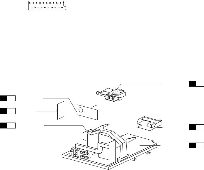
4.3.2Service position SSB
In fact there is no predefined service position for the bottom (B- ) side of the SSB. All relevant test points are located on the A- side (side that is facing the Tuner).
If IC's must be replaced: take the complete panel out of the SIMM-connector.
To get access to the SSB test points, do the following:
2
 3
3
5
1
0946
4
 4
4
CL 965320156_008.eps
060100
Figure 4-2 |
Figure 4-4 |
GB 18 |
|
4. |
|
EM2E |
Mechanical instructions |
1.Put the LSP in service position 1 (as described above).
2.Disconnect the IF-cable from connector 0946 (1).
3.Release the 'top fixation clamp' which holds the SSB (2) and pull the SSB slightly towards the Tuner (3). At the same time, the 2 metal clamps at both sides of the SIMMconnector must be released (4) and the complete SSB can be taken out now by pulling the top-side of the SSB towards the Tuner (5). It 'hinges' in the SIM-connector.
SAM (4005)
SDM (4006)
2 1 
 1 CL 965320156_009.eps 060100
Figure 4-5
1.Once the SSB has been taken out of the connector, the A- side shielding can be removed.
2.After removal of the shielding, the panel can be replaced in its connector in reverse order. Don't forget to reconnect the IF-cable.
3.If necessary for the measurement, the LSP can be put in 'service position 2' (as described above).
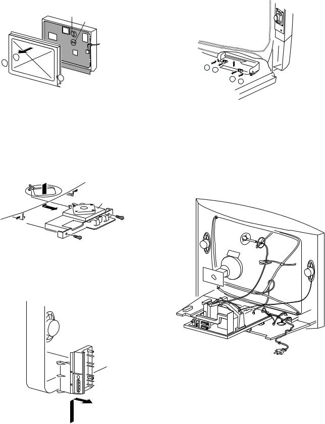
4.3.3Accessing the Top Control panel
1.The complete Side I/O-assembly can be lifted out of the hinge for servicing.
2.The board can easily be removed out of the bracket by releasing the fixation clamps.
4.3.5Accessing the Mains Switch/LED panel
N
P
P
N
CL96532137_010.eps
101199
Figure 4-8
1.Release the two fixation clamps (N) by pushing them upward.
2.At the same time, the complete assy must be pulled backward (P).
3.If necessary, the light guide can be replaced now.
4.The 'Mains Switch/LED'-panel can be removed now by releasing the clamps of the bracket.
4.4 Mounting the Rear Cover
Top control board
CL96532137_009.eps
101199
Figure 4-6
1. Remove the two screws.
2. Pull the board backward.
4.3.4Accessing the Side I/O panel
CL 96532156_010.eps
110100
Figure 4-9
Before mounting the Rear Cover, some checks has to be performed:
• Check whether the Mains Cord is mounted correctly in the guiding brackets.
• Check whether all cables are replaced in their original position. This is very important due to the large 'hot' area of
CL96532137_008.eps
101199 the set. Special attention must be paid to the right
Loudspeaker cable and the degaussing cable.
Figure 4-7
 Loading...