


EverFloTM Oxygen Concentrator
EverFloTM Q OxygenConcentrator
Service & Technical Reference Manual
Page 1 |
EVERFLOTM SERVICE & TECHNICAL INFORMATION |
1039055, VER. 06 |

REVISION HISTORY
|
Revision |
|
|
Description |
|
|
Author |
|
|
|
|
|
|
|
|||
|
|
|
|
|
|
|
|
|
06 |
|
|
Updated to include Field Communications |
|
K. Carter |
|||
|
|
Reformatted |
|
|||||
|
|
|
|
|
|
|
||
|
|
|
|
|
|
|
|
|
Page 2 |
EVERFLOTM SERVICE & TECHNICAL INFORMATION |
1039055, VER. 06 |

Chapter 1. |
INTRODUCTION............................................................................................................ |
5 |
|
1.1 |
EVERFLO OXYGEN CONCENTRATOR OVERVIEW ............................................................................. |
5 |
|
1.2 |
SERVICE NOTICE .................................................................................................................................... |
5 |
|
1.3 |
SERVICE TRAINING................................................................................................................................. |
5 |
|
1.4 |
SERVICE/TECHNICAL SUPPORT STATEMENT.................................................................................... |
5 |
|
Chapter 2. |
WARNINGS & CAUTIONS........................................................................................... |
6 |
|
2.1 |
WARNINGS ............................................................................................................................................... |
6 |
|
2.2 |
CAUTIONS ................................................................................................................................................ |
7 |
|
Chapter 3. |
SPECIFICATIONS & CLASSIFICATIONS .................................................................... |
8 |
|
3.1 |
SPECIFICATIONS..................................................................................................................................... |
8 |
|
Chapter 4. THEORY OF OPERATION .......................................................................................... |
10 |
||
4.1 |
PNEUMATIC OPERATION..................................................................................................................... |
10 |
|
4.2 |
ELECTRICAL OPERATION.................................................................................................................... |
12 |
|
4.3 |
PCA CONTROLLER OVERVIEW........................................................................................................... |
12 |
|
Chapter 5. |
SYSTEM SETUP......................................................................................................... |
14 |
|
5.1 |
INTRODUCTION ..................................................................................................................................... |
14 |
|
5.2 |
SYSTEM SETUP PROCEDURES.......................................................................................................... |
14 |
|
Chapter 6. |
MAINTENANCE........................................................................................................... |
16 |
|
6.1 |
DEALER ROUTINE MAINTENANCE ..................................................................................................... |
16 |
|
6.2 |
EVERFLO OXYGEN CONCENTRATOR MAINTENANCE RECORD.................................................... |
17 |
|
6.3 |
SYSTEM VERIFICATION PROCEDURES ............................................................................................ |
18 |
|
Chapter 7. |
TROUBLESHOOTING & ALARMS ............................................................................. |
31 |
|
7.1 |
INTRODUCTION ..................................................................................................................................... |
31 |
|
7.2 |
INDICATORS & ALARMS....................................................................................................................... |
31 |
|
7.3 |
TROUBLESHOOTING TABLE................................................................................................................ |
32 |
|
7.4 |
SYSTEM PRESSURE TEST TABLE ...................................................................................................... |
39 |
|
Chapter 8. |
REPAIR & REPLACEMENT....................................................................................... |
40 |
|
8.1 |
OVERVIEW ............................................................................................................................................. |
40 |
|
8.2 |
REPAIR KIT REFERENCE TABLE......................................................................................................... |
41 |
|
8.3 |
FILTER COVER REPLACEMENT.......................................................................................................... |
44 |
|
8.4 |
INLET FILTER REPLACEMENT ............................................................................................................ |
45 |
|
8.5 |
REAR CABINET/POWER CORD REPLACEMENT............................................................................... |
46 |
|
8.6 |
O2 QUICK COUPLER REPLACEMENT ................................................................................................ |
49 |
|
|
Page 3 |
EVERFLOTM SERVICE & TECHNICAL INFORMATION |
1039055, VER. 06 |

8.7 |
|
EVERFLO AND EVERFLO Q PRESSURE REGULATOR ASSEMBLY REPLACEMENT.................... |
50 |
|
8.8 |
EVERFLO ULTRAFILL COMPATIBLE PRESSURE REGULATOR ASSEMBLY REPLACEMENT ...... |
52 |
||
8.9 |
|
MAIN PCA REPLACEMENT................................................................................................................... |
55 |
|
8.10 |
SIEVE CANISTER ASSEMBLY REPLACEMENT ............................................................................. |
59 |
||
8.11 |
VALVE SOLENOID REPLACEMENT .................................................................................................. |
63 |
||
8.12 |
COOLING FAN REPLACEMENT ....................................................................................................... |
67 |
||
8.13 |
CAPACITOR REPLACEMENT ........................................................................................................... |
69 |
||
8.14 |
COMPRESSOR REPLACEMENT ...................................................................................................... |
70 |
||
8.15 |
MICRO-DISK FILTER & TUBING REPLACEMENT ........................................................................... |
79 |
||
8.16 |
FLOW METER REPLACEMENT ........................................................................................................ |
80 |
||
8.17 |
FRONT CABINET REPLACEMENT ................................................................................................... |
81 |
||
8.18 |
RETURNS / PACKAGING ................................................................................................................... |
84 |
||
8.19 |
LABELS................................................................................................................................................ |
88 |
||
Chapter 9. |
TESTING ..................................................................................................................... |
90 |
||
9.1 |
|
LONG LIFE FILTER TEST ...................................................................................................................... |
90 |
|
9.2 |
|
EVERFLO SYSTEM FINAL TEST .......................................................................................................... |
90 |
|
9.3 |
|
EVERFLO TEST DATA SHEET............................................................................................................... |
93 |
|
Chapter 10. TOOLS AND EQUIPMENT....................................................................................... |
94 |
|||
10.1 |
ACCEPTABLE TEST EQUIPMENT .................................................................................................... |
95 |
||
Chapter 11. |
SERVICE SOFTWARE............................................................................................. |
96 |
||
11.1 |
EVERFLO SERVICE TOOL................................................................................................................. |
96 |
||
Page 4 |
EVERFLOTM SERVICE & TECHNICAL INFORMATION |
1039055, VER. 06 |

Chapter 1. INTRODUCTION
CAUTION
U.S. federal law restricts this device to sale by or on the order of a physician.
This section provides an introduction to the EverFlo Oxygen Concentrator as well as contact and service training information.
1.1EVERFLO OXYGEN CONCENTRATOR OVERVIEW
The EverFlo Oxygen Concentrator produces concentrated oxygen from room air for delivery to a patient requiring low flow oxygen therapy. The oxygen from the air is concentrated using a molecular sieve and a pressure swing adsorption process. The EverFlo Oxygen Concentrator is not intended to be life supporting or life sustaining.
1.2SERVICE NOTICE
The EverFlo Oxygen Concentrator is designed so that trained Service Technicians can perform repair and testing procedures. Only trained and qualified personnel should repair these products using authorized parts.
1.3SERVICE TRAINING
Philips Respironics offers service training for EverFlo Oxygen Concentrators. Training includes complete disassembly of the device, troubleshooting subassemblies and
components, repair and replacement of components, setup of test equipment, and necessary testing. For more information, contact the Respironics Customer Service department @ 1-800-345-6443.
1.4SERVICE/TECHNICAL SUPPORT STATEMENT
For technical assistance, please contact Philips Respironics Service and Technical Support.
U.S.A. and Canada
Phone: 1-800-345-6443
Fax: 1-800-886-0245
International
Phone: 1-724-387-4000
Fax: 1-724-387-5012
Page 5 |
EVERFLOTM SERVICE & TECHNICAL INFORMATION |
1039055, VER. 06 |

Chapter 2. WARNINGS & CAUTIONS
Warnings and cautions are used throughout this manual to identify possible safety hazards, conditions that may result in equipment or property damage, and important information that must be considered when performing service and testing procedures on the EverFlo Oxygen Concentrator. Please read this section carefully before servicing the EverFlo Oxygen Concentrator. Additional Warning and Cautions can be located in the EverFlo User Manual.
WARNING
Warnings indicate the possibility of injury to people.
CAUTION
Cautions indicate the possibility of damage to equipment.
2.1WARNINGS
WARNINGS
•For proper operation, your concentrator requires unobstructed ventilation. The ventilation ports are located at the top and bottom of the rear cabinet. Keep the device 6 to 12 (15 to 30 cm) inches away from walls that could impede adequate airflow to the device. Always make sure that these areas are not obstructed by items, which may impede ventilation. Do not place concentrator in a small closedspace.
•Servicing of this device must be referred to an authorized and trained Respironics home care provider.
•Oxygen generated by this concentrator is supplemental and should not be considered life
supporting or life sustaining. In certain circumstances, oxygen therapy can be hazardous; any user should seek medical advice prior to using thisdevice.
•Oxygen vigorously accelerates combustion and should be kept away from heat or open flame. Not suitable for use in the presence of a flammable anesthetic mixture with air, with oxygen, or with nitrous oxide.
•Do not smoke or allow others to smoke or have open flames near the concentrator when it is in use.
•Do not use oil or grease on the concentrator or its components as these substances, when combined with oxygen, can greatly increase the potential for a fire hazard and personal injury.
•Do not use the concentrator if either the plug or power cord is damaged. Do not use extension cords or electrical adaptors.
•Do not attempt to clean the concentrator while it is plugged into an electrical outlet.
Page 6 |
EVERFLOTM SERVICE & TECHNICAL INFORMATION |
1039055, VER. 06 |

WARNINGS
•Avoid handling the molecular sieve material. Respironics recommends the return of the sieve canister assembly to Respironics for any service that involves sieve disposal.
•Use extreme caution when handling the compressor capacitor as it holds an electrical charge until is it properly discharged.
•Device operation above or outside of the voltage, LPM, temperature, humidity and/or altitude values specified may decrease oxygen concentrationlevels.
•If the EverFlo Oxygen Concentrator has been subjected to sub-freezing temperatures for an extended period, it should be allowed to warm up to the stated operating temperatures before power up. Failure to do so could result in improper performance and or alarm conditions until the device reaches normal operating temperatures.
2.2CAUTIONS
CAUTIONS
U.S. federal law restricts this device to sale by or on the order of a physician. Do not place liquids on or near the device.
If liquid is spilled on the device, turn the power off and unplug from electrical outlet before attempting to clean up a spill.
When using liquid leak detector, be careful not to allow it to contact electrical parts. Make sure connections of fittings, tubing, and hoses aresecure.
Be cautious when using thread sealants because they can cause extensive damage to the internal parts of the device if allowed within tubing orfittings.
Page 7 |
EVERFLOTM SERVICE & TECHNICAL INFORMATION |
1039055, VER. 06 |

Chapter 3. SPECIFICATIONS & CLASSIFICATIONS
3.1SPECIFICATIONS
Model |
|
Voltage |
|
Operational |
|
Power |
|
Oxygen |
|
Sound |
|
Weight |
|
|
|
|
Power |
|
Consum |
|
Concentrati |
|
|
|
|||
Numbers |
|
|
Level |
|
|||||||||
|
|
|
Frequency |
|
ption |
|
on Zero to |
|
|
|
|
||
|
|
|
|
|
|
||||||||
|
|
|
|
|
|
|
|
Maximum |
|
|
|
|
|
|
|
|
|
|
|
|
|
Flow LPM |
|
|
|
|
|
1020000 |
|
|
|
|
|
|
|
|
|
|
|
|
|
1020001 |
|
120 VAC + |
|
|
|
350 W |
|
|
|
|
|
|
|
1020002 |
|
|
60 Hz |
|
|
90 - 95.5% |
|
45 dBA typ |
|
31 lbs (14 kg) |
|
||
1020003 |
|
10% |
|
|
At 120 VAC |
|
|
|
|
||||
|
|
|
|
|
|
|
|
|
|
|
|||
1039362 |
|
|
|
|
|
|
|
|
|
|
|
|
|
1039363 |
|
|
|
|
|
|
|
|
|
|
|
|
|
1020002BR |
|
|
|
|
|
350 W |
|
|
|
|
|
|
|
1020003BR |
|
120 VAC + |
|
60 Hz |
|
|
90 - 95.5% |
|
43 dBA typ |
|
31 lbs (14 kg) |
|
|
1039364 |
|
10% |
|
|
At 120 VAC |
|
|
|
|
||||
|
|
|
|
|
|
|
|
|
|
|
|||
1039365 |
|
|
|
|
|
|
|
|
|
|
|
|
|
1020014 |
|
120 VAC + |
|
60 Hz |
|
350 W |
|
90 - 95.5% |
|
<40 dBA |
|
31 lbs (14 kg) |
|
1020015 |
|
10% |
|
|
|
At 120 VAC |
|
|
|
typ |
|
|
|
1020006 |
|
|
|
|
|
|
|
|
|
|
|
|
|
1020009 |
|
|
|
|
|
|
|
|
|
|
|
|
|
1020010 |
|
|
|
|
|
|
|
|
|
|
|
|
|
1020011 |
|
230 VAC + |
|
|
|
<300 W |
|
|
|
|
|
|
|
1020012 |
|
|
50 Hz |
|
|
90 - 95.5% |
|
43 dBA typ |
|
33 lbs (15 kg) |
|
||
1020016 |
|
10% |
|
|
At 230 VAC |
|
|
|
|
||||
|
|
|
|
|
|
|
|
|
|
|
|||
1020017 |
|
|
|
|
|
|
|
|
|
|
|
|
|
1020020 |
|
|
|
|
|
|
|
|
|
|
|
|
|
1039366 |
|
|
|
|
|
|
|
|
|
|
|
|
|
1039370 |
|
|
|
|
|
|
|
|
|
|
|
|
|
1020008 |
|
230 VAC + |
|
|
|
<300 W |
|
87 - 95.5% |
|
|
|
|
|
1039368 |
|
|
50 Hz |
|
|
|
43 dBA typ |
|
33 lbs (15 kg) |
|
|||
|
10% |
|
|
At 230 VAC |
|
|
|
|
|||||
1104000 |
|
|
|
|
|
|
|
|
|
|
|
||
|
|
|
|
|
|
|
|
|
|
|
|
|
|
1020007 |
|
230 VAC + |
|
50 Hz |
|
<300 W |
|
87 - 95.5% |
|
<40 dBA |
|
33 lbs (15 kg) |
|
1039367 |
|
10% |
|
|
|
At 230 VAC |
|
|
|
typ |
|
|
|
1125558 |
|
230 VAC + |
|
50 Hz |
|
<300 W |
|
90 - 95.5% |
|
<40 dBA |
|
33 lbs (15 kg) |
|
|
|
10% |
|
|
|
At 230 VAC |
|
|
|
typ |
|
|
|
1020004 |
|
220 VAC + |
|
60 Hz |
|
320 W |
|
90 - 95.5% |
|
45 dBA typ |
|
33 lbs (15 kg) |
|
1020005 |
|
10% |
|
|
At 220 VAC |
|
|
|
|
||||
|
|
|
|
|
|
|
|
|
|
|
|||
1020013 |
|
220 VAC + |
|
60 Hz |
|
<300 W |
|
90 - 95.5% |
|
43 dBA typ |
|
33 lbs (15 kg) |
|
|
10% |
|
|
At 220 VAC |
|
|
|
|
|||||
|
|
|
|
|
|
|
|
|
|
|
|
||
1102443 |
|
230 VAC + |
|
60 Hz |
|
<300 W |
|
90 - 95.5% |
|
43 dBA typ |
|
33 lbs (15 kg) |
|
|
10% |
|
|
At 230 VAC |
|
|
|
|
|||||
|
|
|
|
|
|
|
|
|
|
|
|
Page 8 |
EVERFLOTM SERVICE & TECHNICAL INFORMATION |
1039055, VER. 06 |

|
All Models |
|
|
||
|
|
|
Dimensions |
22.8” (58 cm) x 15” (38 cm) x 9.5” (24 cm) (H x W x D) |
|
|
|
|
Oxygen Purity Alarms |
Low Oxygen at 82% purity (For OPI models only), Very Low Oxygen |
|
at < 70% |
||
|
||
|
|
|
Operating Temperature |
55o F to 90o F (13o C to 32o C) |
|
Storage and Transport Temperature |
29o F to 160o F (-34o C to 71o C) |
|
Relative Humidity |
15 to 95%, noncondensing |
|
|
|
|
Outlet Pressure |
5 to 7 psi (0.34 to 0.48 Bar) |
|
|
|
|
|
0 to 7,500 ft (0 to 2,286 m) meets specifications |
|
Operating Altitude |
7,500 to 13,123 ft (2286 to 4000 m) not specified, exceeds specified |
|
|
||
|
operating altitude |
|
|
|
|
Maximum Flow at 0 & 7 kPa Outlet Pressure |
5 LPM (3 LPM During trans fill operation) |
|
|
|
|
Pressure Relief Valve |
49 to 55 psi (338 to 378 kPa) |
|
|
|
Each EverFlo unit is measured in the factory with an Oxygen Analyzer that measures oxygen concentration with an accuracy specification of +/- .1 %. When using an Oxygen Analyzer with an accuracy specification of +/- 2 % to test the Oxygen Concentration for an EverFlo Oxygen Concentrator, you may receive inaccurate readings below the acceptable pass criteria for the device. This 2% offset should be taken in to consideration when determining if the EverFlo is functioning properly. A more accurate Oxygen Analyzer may also be used for a more precise measurement of the oxygen purity. As an example, a unit could be measured in the factory with the +/- 1% Oxygen Analyzer to measure 91.1%. If this same unit is then measured with a +/- 2% Oxygen Analyzer, the reading could display a result of 89.1%. With the +/- 2% Oxygen Analyzer, it may inaccurately look like the unit falls below the 9095.5% specification, when in fact the unit is within specification.
Refer to User Manual (1041063) for classification, standards compliance, and EMC requirements.
Page 9 |
EVERFLOTM SERVICE & TECHNICAL INFORMATION |
1039055, VER. 06 |

Chapter 4. THEORY OF OPERATION
This section describes the theory of operation for the EverFlo Oxygen Concentrator.
4.1PNEUMATIC OPERATION
Refer to Figure 4-1 while reading the following discussion.
The room air is drawn into the unit through the air inlet filter by the compressor. The compressed air is routed to the sieve beds through an electronically controlled Solenoid Valve Assembly. The Solenoid Valve alternates the airflow to a pair of sieve beds that allows Oxygen production. The Solenoid Valve Assembly also alternates the flow through the sieve beds to allow purging of the Nitrogen molecules from the sieve beds.
At startup, the valve/solenoid is de-energized allowing compressed air to flow through both sieve beds until the pressure sensor builds up to switching pressure. At switching pressure, a 12-volt signal is received at the valve/solenoid closing off the input and allowing the compressed air to cycle through one of the sieve beds. As the air is cycled through one of the sieve beds, the molecular sieve material traps the Nitrogen molecules from the air and allows the Oxygen enriched air to flow through the sievebed.
At 5 liters of flow, approximately 1/3 of the Oxygen enriched air enters the product tank and the other 2/3 of the Oxygen enriched air is passed through an orifice in the sieve bed to purge the trapped Nitrogen molecules from the sieve bed, allowing the sieve material to be ready for Oxygen production during the next cycle.
The concentrated Oxygen is stored in the product tank. The product tank is continuously filled with concentrated Oxygen and the output from the product tank is regulated at 5.5 psig nominal. The product tank pressure is continuously monitored using a pressure sensor. The stored Oxygen is delivered to the patient through a pressure regulator, an externally adjustable flow meter and a microbial filter.
NOTE
In the beginning, the 230V units, had an orifice built into the purge valve. The electronically controlled purge valve controls the Oxygen flow timing from one sieve bed to the other based on the flow meter setting.
Page 10 |
EVERFLOTM SERVICE & TECHNICAL INFORMATION |
1039055, VER. 06 |
Figure 4-1: Pneumatic Block Diagram (Non-O2 Piloted)
Page 11 |
EVERFLOTM SERVICE & TECHNICAL INFORMATION |
1039055, VER. 06 |

4.2ELECTRICAL OPERATION
The EverFlo Concentrator is a medical device, which produces concentrated oxygen from room air for delivery to a patient. It uses a molecular sieve and a pressure swing adsorption process to concentrate oxygen from air. The device consists of filters, a compressor, a sieve canister module, a set of valves, a microprocessor-based electronic controller PCA, a flow meter and a cooling fan – all contained within a plastic enclosure.
The EverFlo Embedded Software—via the microprocessor contained on the PCA Controller—controls the sieve valves used to generate the oxygen, measures/monitors the pressure & oxygen levels, drives the Elapsed Time counter (Hour meter), reports exception conditions to the User via visual and audible indicators and provides diagnostic information to a Host computer via an RS232 communications interface.
4.3PCA CONTROLLER OVERVIEW
All the electric / electronic functions of the EverFlo Concentrator reside on the PCA Controller. A block diagram of the PCA controller is provided in Figure A. The reader is urged to continually refer to this diagram when reading the remaining sections of this document.
The PCA controller can be sub-divided into 2 major sections:
1.Power distribution and DC voltage generation.
2.Monitoring / Control / User Interface.
Figure 4-2: EverFlo PCA Controller Block Diagram
Page 12 |
EVERFLOTM SERVICE & TECHNICAL INFORMATION |
1039055, VER. 06 |

4.3.1POWER
The AC mains power, via the line cord, is brought onto the PCA and the “switched” AC is distributed to the Compressor, the Cooling Fan and to the AC to DC conversion module. The DC voltages that are generated are used to power the remainingcircuitry.
The PCA contains a 1 Farad “super capacitor” which is used to sound the Audible Indicator when the AC mains power is absent AND the mains switch is in the ON position. The purpose is to alert the User to the fact that there has been a loss of AC mains power (that is, an AC mains power failure, a plug removal, a blown fuse). The circuitry functions as follows:
1.During normal operation, the capacitor is energized (charged) using the +5 VDC. The capacitor reaches full charge after approximately ½ hour of systemon-time.
2.The mains switch has a 2nd set of contacts that are used to determine whether the switch is open or closed. If the switch is closed (in the ON position) and the microprocessor is not functional (no DC power), then the backup circuitry is such that it will turn on the Audible Indicator, using the “super cap” as its energy source.
The “super cap” is capable of sounding the Audible Indicator for a period of greater than 8 minutes, given that it is fully charged.
4.3.2MICROPROCESSOR AND ASSOCIATED CIRCUITRY
The remainder of the PCA controller electronics is centered around the MSP430F155 microprocessor. The microprocessor is the only processing element contained in the EverFlo concentrator. In addition to the microprocessor, the “remaining circuitry” consists of sensors, LEDS, a piezo Audible Indicator, amplifiers / signal conditioners, communication buffers and discrete components.
The embedded software, in conjunction with the microprocessor and its associated hardware, is used to control the sieve valves, measure/monitor the pressure & oxygen levels, control the oxygen sensor, drive the Hour meter, reports exception conditions to the User via visual and audible indicators and provide diagnostic information to a Host computer via an RS232 communications interface.
Page 13 |
EVERFLOTM SERVICE & TECHNICAL INFORMATION |
1039055, VER. 06 |

Chapter 5. SYSTEM SETUP
NOTE
Please refer to the appropriate User Manual for additional information.
5.1INTRODUCTION
This section provides information regarding setup and operation of the EverFlo Oxygen Concentrator as needed for servicing, repairing, and testing the device.
5.2SYSTEM SETUP PROCEDURES
1.Select a location that allows the concentrator to draw in room air without being restricted. Make sure that the device is at least 6 to 12 inches (15 to 30 cm) away from walls, furniture, and especially curtains that could impede adequate airflow to the device. Do not place the device near any heat source.
2.Plug the EverFlo Oxygen Concentrator into an electrical outlet.
3.If you are NOT using a humidifier, connect the cannula to the EverFlo Oxygen Outlet Port, as shown below. Proceed to step 4.
4.If you are using a humidifier follow thesesteps:
a.Open the filter door on the back of thedevice.
b.Remove the humidifier connector tube from the back of the filter door and replace the filter door.
c.Fill the humidifier with water following the manufacturer’s instructions.
d. Mount the filled humidifier on the top of the EverFlo device inside the velcro strap.
e.Tighten the velcro strap around the bottle and secure it so it is held firmly in place.
f.Connect the humidifier connector tube (that you retrieved from the filter door) to the Oxygen Outlet Port.
g.Connect the other end of the humidifier connector tube to the top of the humidifier withthe elbow in the tubing facing the front.
h.Connect your cannula to the humidifier bottle according to the humidifier bottle manufacturer’s specifications.
Page 14 |
EVERFLOTM SERVICE & TECHNICAL INFORMATION |
1039055, VER. 06 |

5.Press the power switch to the On [I] position. Initially, all the LEDS will illuminate and the audible alert will sound for a few seconds. After that time, only the green LED should remain lit. You can begin breathing from the device immediately even though it typically takes 10 minutes to reach oxygen purity specifications. The device normally takes 10 minutes to reach oxygenpurity specifications.
6.Adjust the flow to the proper setting by turning the knob on the top of the flow meter until the ball is centered on the line marking the specific flowrate.
7.Be sure oxygen is flowing through the cannula. If it is not, refer to the Troubleshooting section of this manual.
8.When you are not using the oxygen concentrator, press the power switch to the Off [O] position.
Page 15 |
EVERFLOTM SERVICE & TECHNICAL INFORMATION |
1039055, VER. 06 |

Chapter 6. MAINTENANCE
6.1DEALER ROUTINE MAINTENANCE
This section describes scheduled and routine maintenance procedures. Normal routine maintenance involves periodic checking, cleaning, and or replacing the following items as necessary:
•Inlet Filter
•Micro-Disk Filter
•Cabinet cleaning
•LPM flow setting to the prescribed level
•Oxygen concentration level
Routine maintenance is very important in prolonging dependability and in reducing costly repairs. Long-term maintenance and regular checking of the filters helps assure the efficient operation of the unit.
6.1.1FILTERS
Respironics recommends checking and replacing the Inlet Filter every two (2) years. Respironics also recommends checking and replacing the Micro-Disk filter as necessary.
6.1.2CABINET
Commensurate with hospital or homecare policies, Respironics recommends cleaning the cabinet and inspecting for damage as necessary. Ensure that the small holes on the Inlet Filter door are unobstructed. Refer to the Tools and Equipment section for approved cleaning solution.
6.1.3FLOW SETTING
Commensurate with hospital or homecare policies, Respironics recommends verifying the patient flow setting as necessary.
6.1.4OXYGEN CONCENTRATION VERIFICATION
Commensurate with hospital or homecare policies, Respironics recommends verifying the oxygen concentration level per homecare provider's policies as necessary. Refer to the Testing section for more detailed instructions on how to check the oxygen concentration level.
6.1.5COMPRESSOR
Respironics does not require routine maintenance or recommend field service of the EverFlo Oxygen Concentrator compressor. The compressor may require replacement when:
•The system pressure is not within specifications and there are no leaksdetected.
•The compressor bearings have worn to a point that make the compressor noticeably louder.
6.1.6HUMIDIFIER CONNECTOR TUBE AND CONNECTOR
Commensurate with hospital or homecare policies, Respironics recommends disinfecting the tube and connector using 70% isopropyl alcohol.
Page 16 |
EVERFLOTM SERVICE & TECHNICAL INFORMATION |
1039055, VER. 06 |

6.2EVERFLO OXYGEN CONCENTRATOR MAINTENANCE RECORD
MODEL NUMBER |
SERIAL NUMBER |
|
|
|
|
DATE PURCHASED
|
|
FILTERS |
OXYGEN |
|
DATE/HOURS/LPM |
(Clean & Replace as Necessary) |
CONCENTRATION |
||
(Record at Each Check) |
Inlet |
|
Micro-Disk |
(Check Level) |
|
|
|
|
|
|
|
|
|
|
|
|
|
|
|
|
|
|
|
|
|
|
|
|
|
|
|
|
|
|
|
|
|
|
|
|
|
|
|
|
CABINET |
FLOW SETTING |
(Clean and Inspect as Necessary) |
(Check Setting) |
|
|
|
|
|
|
|
|
|
|
|
|
|
|
|
|
Page 17 |
EVERFLOTM SERVICE & TECHNICAL INFORMATION |
1039055, VER. 06 |

6.3SYSTEM VERIFICATION PROCEDURES
The following procedures may be performed at any time to ensure that the EverFlo Concentrator is functioning properly.
6.3.1SYSTEM SELF TEST AND START UP TEST
1.Connect the power cord to the proper power source.
2.Turn on the unit by moving the power switch to the ON (I) position and verify the following:
• All LEDs light up and the audible alarm sounds for two seconds.
•The unit starts to run.
•The red and yellow LED lights go off and the audible alarmstops.
•The green LED stays on.
6.3.2POWER LOSS ALARM TEST
1.Test the power loss alarm as follows:
a. Connect the device to a proper power source.
a.Let the device warm up for two minutes to charge the capacitor.
b.Disconnect the device from the power source and move the power switch to the On (I) position and verify an audible alarm soundscontinuously.
c.The alarm should have sufficient power to sound for 10 minutes. Verify that the EverFlo Device alarms.
d.If the audible alarm does not sound, replace the Main PCA.
6.3.3OUTLET/REGULATED PRESSURE TEST
1.Power up the unit and allow it to run for at least two minutes to stabilize.
2.Set the flow meter to 5 LPM (1 LPM for units equipped with pediatric flowmeters).
NOTE
If using the Concentrator tool kit (H647), be sure to remove the DISS outlet fitting from the tubing before proceeding to step 3.
Page 18 |
EVERFLOTM SERVICE & TECHNICAL INFORMATION |
1039055, VER. 06 |
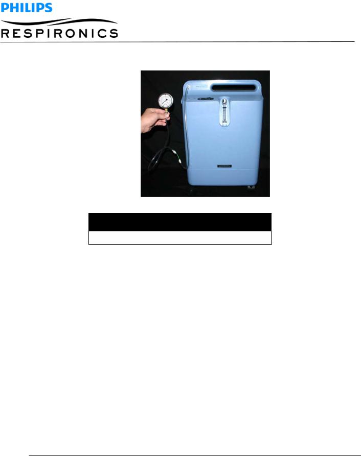
3.Connect the pressure gauge from the tool kit to the outlet barb. The flow ball should drop to 0.0 LPM.
NOTE
Be sure to hold the pressure gauge in a vertical position.
4.If the outlet pressure does not fall between 5.0 and 7.0 psig, perform steps 5 through 14. If the pressure does fall between 5.0 and 7.0 psig, remove pressure gauge, the test is now complete.
5.Turn the unit off.
6.Remove the pressure gauge from the outlet barb.
7.Remove the front and rear cabinets.
Page 19 |
EVERFLOTM SERVICE & TECHNICAL INFORMATION |
1039055, VER. 06 |

8.Insert a “T” from the tool kit in between the regulator and the clear oxygen tubing and connect the pressure gauge.
9.Turn the device on and set the flow meter to 5 LPM (1 LPM for units equipped with pediatric flow meters).
10.With the gauge held in a vertical position, verify that the regulated pressure is at 5.5 ± 0.25 psig.
11.If the regulated pressure needs adjusted, place a 3/32” Allen wrench in the adjusting screw on the end of the regulator.
NOTE
If the regulated pressure is low, turn the wrench clockwise to increase the regulated pressure. If the regulated pressure is high, turn the wrench counter-clockwise.
12.Disconnect the pressure gauge and “T” fitting.
13.Reconnect the clear oxygen tubing to the pressure regulator.
14.Install the front and rear cabinets.
Page 20 |
EVERFLOTM SERVICE & TECHNICAL INFORMATION |
1039055, VER. 06 |
6.3.4SYSTEM PRESSURE TEST
The system pressure test is used to verify the proper operation of the EverFlo Compressor and Sieve Canister Assemblies.
NOTE
If pressures are not within the normal operating pressure, it does not necessarily indicate an issue with the concentrator. The Final Test located in the Testing Chapter of this manual is the only test to be used when determining a known good EverFlo Concentrator from a Concentrator requiring repair.
1.Run the unit with the front and rear cabinets in place for a minimum of ten minutes.
2.Set the flow to 5 LPM (1 LPM for units equipped with pediatric flowmeters).
3.Turn off the Everflo Oxygen Concentrator.
4.Remove the front and rear cabinets from theunit.
5.Disconnect the yellow pressure tubing from the fitting on the PCA. Using the pressure gauge, “T” fitting, and pressure tubing supplied with the Concentrator tool kit, connect to the Pressure Regulator as shown below.
6.Turn the unit on and allow the unit to cycle for at least two (2) minutesto stabilize.
7.Hold the pressure gauge in a vertical position.
8.Verify pressures against the table below. This table is a reference guideline for system pressures and troubleshooting. If a value is measured outside of these ranges, it may not mean the unit has a fault. If the Outlet Pressure and Outlet Oxygen values are within tolerances, and the unit is not alarming, the unit should be considered acceptable.
Page 21 |
EVERFLOTM SERVICE & TECHNICAL INFORMATION |
1039055, VER. 06 |

EverFlo |
Normal Pressure for |
Normal Pressure for |
|||
Model |
units equipped with |
units without Purge |
|||
|
Purge Valves |
|
Valves |
||
|
|
|
|
|
|
|
Min |
Max |
Min |
|
Max |
1020000 |
NA |
NA |
15 |
|
27 |
1020001 |
|
|
|
|
|
1020002 |
|
|
|
|
|
1020003 |
|
|
|
|
|
1020002BR |
|
|
|
|
|
1020003BR |
|
|
|
|
|
1039362 |
|
|
|
|
|
1039363 |
|
|
|
|
|
|
|
|
|
|
|
1020004 |
NA |
NA |
NA |
|
NA |
1020005 |
|
|
|
|
|
|
|
|
|
|
|
1020006 |
16 |
24 |
14 |
|
25 |
1020009 |
|
|
|
|
|
1020010 |
|
|
|
|
|
1020011 |
|
|
|
|
|
1020012 |
|
|
|
|
|
1020016 |
|
|
|
|
|
1020017 |
|
|
|
|
|
1039366 |
|
|
|
|
|
1039368 |
|
|
|
|
|
1039370 |
|
|
|
|
|
1020007 |
12 |
22 |
12 |
|
23 |
1020008 |
|
|
|
|
|
1039367 |
|
|
|
|
|
|
|
|
|
|
|
1020013 |
NA |
NA |
11 |
|
22 |
|
|
|
|
|
|
1020014 |
NA |
NA |
14 |
|
24 |
1020015 |
|
|
|
|
|
1039364 |
|
|
|
|
|
1039365 |
|
|
|
|
|
|
|
|
|
|
|
9. Record the peak pressure for four cycles.
CYCLE 1 |
|
CYCLE 2 |
|
CYCLE 3 |
|
CYCLE 4 |
|
|
|
|
|
|
|
|
|
|
|
|
|
|
Page 22 |
EVERFLOTM SERVICE & TECHNICAL INFORMATION |
1039055, VER. 06 |
10. Confirm that all peaks are within one (1) psig of each other.
NOTE
If the four cycles are not within specification, refer to the troubleshooting section of the service manual.
11.Turn off the EverFlo Concentrator and disconnect the pressure gauge, “T” fitting, and tubing. Reconnect the yellow tubing to the Pressure Regulator Adaptor located on the top of the Sieve Canister Assembly.
12.Install the front and rear cabinets.
6.3.5OXYGEN OUTPUT TEST
1.Power up the concentrator and allow it to run for a minimum of 15minutes.
2.Connect a calibrated oxygen analyzer to the outlet fitting of the concentrator.
3.Set the flow to 5 LPM (1 LPM for units equipped with pediatric flowmeters).
4.Verify the oxygen reading is as follows:
Page 23 |
EVERFLOTM SERVICE & TECHNICAL INFORMATION |
1039055, VER. 06 |

MODEL NUMBER |
OXYGEN PURITY |
|
|
1020000, 1020001, |
> 90% |
1020002, 1020003, |
|
1020002BR, 1020003BR |
|
1020004, 1020005, |
|
1020006, 1020009, |
|
1020010, 1020011, |
|
1020012, 1020013, |
|
1020014, 1020015, |
|
1020016, 1020017, |
|
1039362, 1039363 |
|
1039364, 1039365 |
|
1039366, 1039368, |
|
1039370 |
|
|
|
1020007, 1020008, |
> 87% |
1039367 |
|
|
|
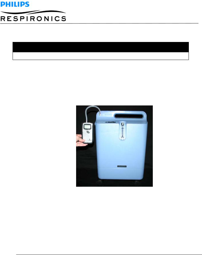
6.3.6MAIN PCA OXYGEN VERIFICATION (OPI UNITS ONLY)
This procedure verifies that the Main PCA is operating properly.
1.Plug the unit into a power outlet.
2.Turn the device on, set the flow to 5.0 LPM, and let it run for 10 minutes.
3.If either the yellow or red LED illuminates after 10 minutes, perform the oxygen output test with a calibrated oxygen analyzer. If the red LED illuminates, the audible alarm should also sound atthe same time.
NOTE
The oxygen analyzer used in the following steps must be calibrated to meet the manufacturer’s specifications.
If the device is alarming and the oxygen concentration is measured at 82% or higher, check the device for leaks. If no leaks are found then replace the Main PCA.
Page 24 |
EVERFLOTM SERVICE & TECHNICAL INFORMATION |
1039055, VER. 06 |

6.3.7COMPRESSOR TEST
This procedure verifies if the Compressor is working properly.
EQUIPMENT REQUIRED FOR OPTION 1
Item |
|
Reference Part No. |
Description |
Picture |
|
|
|
|
|
|
|
1 |
|
McMaster-Carr: Qty 1 |
White Polypropylene Barbed Tube Fitting |
|
|
|
|
of Part #: 5121K851 |
Reducing Tee for 3/8" X 1/8" X 3/8" Tube |
|
|
|
|
|
ID |
|
|
|
|
|
|
|
|
2 |
|
McMaster-Carr: Qty 1 |
Compact Plastic Needle Valve 3/8" Barb X |
|
|
|
|
of Part #: 7781K33 |
3/8" Barb Connections |
|
|
|
|
|
|
|
|
3 |
|
McMaster-Carr: Qty |
Multipurpose Gauge +/-2% Mid-Scale |
|
|
|
|
of 1 of Part #: |
Accuracy 2" Dial, 1/4" NPT Male Bottom, 0 |
|
|
|
|
4089K13 |
- 60 PSI |
|
|
|
|
|
|
|
|
4 |
|
McMaster-Carr: Qty |
High Pressure Tubing, 1/8” ID, 3/8” OD, |
|
|
|
|
of 1 of Part #: |
1/8” Wall |
|
|
|
|
5439K19 |
|
|
|
|
|
|
|
|
|
5 |
|
McMaster-Carr: Qty 1 |
Durable Nylon Single-Barbed Tube Fitting |
|
|
|
|
of Part #: 2974K278 |
Reducing Coupling for 1" X 1/2" Tube ID |
|
|
|
|
(Same as 5463K653) |
White |
|
|
|
|
|
|
|
|
|
Page 25 |
EVERFLOTM SERVICE & TECHNICAL INFORMATION |
1039055, VER. 06 |
||

Item |
Reference Part No. |
Description |
Picture |
|
|
|
|
6 |
|
Hose Clamp, Qty 5 Clamping range of 1/4” |
|
|
|
|
|
|
|
to 5/8” |
|
|
|
|
|
7 |
|
18” Patient Tubing, Qty 1 |
|
|
|
|
|
|
|
|
|
8 |
|
TSI Flow Meter, Qty 1 |
|
|
|
|
|
9 |
|
High-Pressure Tygothane Polyurethane |
|
|
|
Tubing Clear, 3/8" ID, 1/2" OD, 1/8" Wall. |
|
|
|
10’L |
|
|
|
|
|
10 |
|
FDA White Nylon Single Barbed Tube |
|
|
|
|
|
|
|
Fitting Adapter for 1/8” Tube ID X ¼” FNPT |
|
|
|
|
|
11 |
|
Stopwatch |
|
|
|
|
|
|
|
|
|
Page 26 |
EVERFLOTM SERVICE & TECHNICAL INFORMATION |
1039055, VER. 06 |
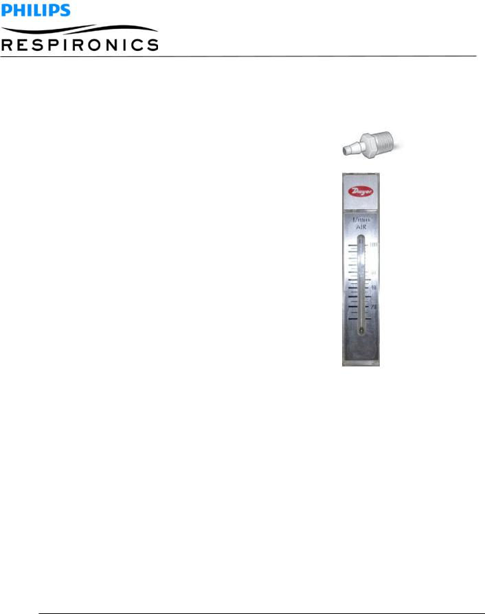
EQUIPMENT REQUIRED FOR OPTION 2
Items 1-4, 6, 9, and 10 as detailed above with the addition of the following items:
ID |
Reference Part No. |
Description |
Picture |
|
|
|
|
1 |
|
Male Tube Adapter 1/8” NPT x 3/8” Barb, |
|
|
|
McMaster-Carr: Part # 5372K116 |
|
|
|
|
|
2 |
|
Flow Meter, Dwyer Instruments Part # RMA- |
|
|
|
|
|
|
|
25 |
|
|
|
|
|
ASSEMBLY INSTRUCTIONS FOR EQUIPMENT OPTION 1
1.Connect the compressor blue outlet tube to Barbed Tube Fitting Reducing Tee (#1) and secure with a hose clamp (#6).
2.Thread the Barbed Tubing Fitting Adapter (#10) to the gauge (#3) using Teflon tape.
3.Connect the Tubing Fitting Adapter (#10) to the Reducing Tee (#1) using the High Pressure Tubing (#4).
4.Install the High Pressure Clear Tubing (#9) to the Reducing Tee (#1) and the Needle Valve (#2) and secure with hose clamps (#6).
5.Install the High Pressure Clear Tubing (#9) to the Needle Valve (#2) and the Single Barbed Tube Fitting (#5) and secure with hose clamps (#6).
6.Install the 18” Patient Tubing (#7) to the Single Barbed Tube Fitting (#5) and the TSI Flow Meter (#8).
7.Install the power adapter to the TSI Flow Meter (#8) and plug into a 120 VAC/60 Hz outlet.
Page 27 |
EVERFLOTM SERVICE & TECHNICAL INFORMATION |
1039055, VER. 06 |

10
8
ASSEMBLY INSTRUCTIONS FOR EQUIPMENT OPTION 2
1.Connect the compressor blue outlet tube to Barbed Tube Fitting Reducing Tee (#1) and secure with a hose clamp (#6).
2.Thread the Barbed Tubing Fitting Adapter (#10) to the gauge (3) using Teflon tape.
3.Connect the Tubing Fitting Adapter (#10) to the Reducing Tee (#1) using the High Pressure Tubing (#4).
4.Install the High Pressure Clear Tubing (#9) to the Reducing Tee (#1) and the Needle Valve (#2) and secure with hose clamps (#6).
5.Install the High Pressure Clear Tubing (#9) to the Needle Valve (#2)
6.Install the 1/8” Male Tube Adapter (#12) to the Flow Meter (#13) using Teflon tape.
7.Install the High Pressure Clear Tubing (#9) to the 3/8” Male Tube Adapter (#12) and secure with a hose clamp (#6).
1
1
1
|
|
|
|
|
Page 28 |
EVERFLOTM SERVICE & TECHNICAL INFORMATION |
1039055, VER. 06 |
||

ASSEMBLY INSTRUCTIONS FOR EQUIPMENT OPTION 3
Option 3 is only available in SCMS (equipment not shown above).
1.Attach the TSI flow meter to the inlet filter.
2.Attach the grommet to the inlet adapter.
3.Inset the pipe nipple into a length of hose. (@ 7” in length)
4.Attach the hose to the Compact Plastic Needle Valve 3/8" Barb X 3/8" Barb Connections.
5.Join a short length of hose to the white polypropylene barbed tube.
6.Connect the pressure gage to the tee fitting on the barbed tube.
7.Attach a length of blue hose (30” in length) from the barb fitting to a brass fitting. This is the test end of the device for testing the compressors for flow and pressure.
8.Insert an inline muffler to help collect any sieve material in the test line.
9.Use clamps to secure the fittings together.
PROCEDURE
1.Follow the procedures detailed in the EverFlo Service Manual for the removal of the following components:
a.Filter Cover
b.Inlet Filter
c.Rear Cabinet
Page 29 |
EVERFLOTM SERVICE & TECHNICAL INFORMATION |
1039055, VER. 06 |

2.Remove the blue hose running from the Compressor to the Sieve Canister Assembly by carefully cutting the one-eared clamp.
3.Connect the Compressor blue outlet tube to the Test Fixture’s Barbed Tube Fitting Reducing Tee.
4.Install the Inlet Filter to the Compressor’s Inlet Boot.
5.If using Test Fixture Option 1, turn ON the flow meter.
6.Ensure is Compact Plastic Needle Valve is fully open.
7.Turn ON the EverFlo power switch.
8.Start the stopwatch.
9.Adjust Compact Plastic Needle Valve to achieve 20 psi pressure. (turning clockwise to increase pressure and turning counter-clockwise to decrease pressure)
10.When time reaches 1 minute, observe and record LPM reading from Flow Meter.
11.Stop the stopwatch.
12.A reading ≥ 69 LPM indicates a “PASS” for the 0.44 compressor, a reading < 69 LPM indicates a “FAIL”.
13.A reading ≥ 63 LPM indicates a “PASS” for the 0.38 compressor, a reading of < 63 LPM indicates a “FAIL”
14.If the Compressor failed, replace the compressor as per the Service Manual Compressor Replacement instruction.
15.If the Compressor passed, continue to troubleshoot as per the System Verification Procedures in the Service Manual.
Compressor Table
EVERFLO .38 COMPRESSOR-120V (MODEL 1098014 OR 1122381)
≤ 63.0 LPM indicates a “FAIL”
≤ 69.0 LPM indicates a “FAIL”.
EverFlo Compressor-120V .44 (MODEL 1098014 OR 1122381)
≤ 56.0LPM indicates a “FAIL”.
PRI Compressor model 1082141 (115, 60Hz and .38 stroke)
≤ 65.0 LPM indicates a “FAIL”.
PRI Compressor model 1082142 (115, 60Hz and .44 stroke)
≤ 68.0 LPM indicates a “FAIL”.
GSE compressor (115, 60Hz and .45 stroke)
Page 30 |
EVERFLOTM SERVICE & TECHNICAL INFORMATION |
1039055, VER. 06 |
 Loading...